Книги
Putnam
G.Swanborough, P.Bowers
United States Military Aircraft since 1909
93
G.Swanborough, P.Bowers - United States Military Aircraft since 1909 /Putnam/
AVRO 504K
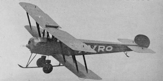
The Avro 504 was a pre-war design, notable as a light bomber in the early days of World War I but whose greatest fame was earned as Britain’s principal primary trainer of the World War I years. The A.E.F. bought 52 504Ks for training in England after several had been sent to the U.S. for evaluation. At least seven were shipped to the U.S. at war’s end and given U.S. serial numbers 62953/62959.
Span 36 ft.; length 29 ft. 5in.; wing area, 330 sq. ft.; gross weight, 1,829 lb.; high speed, 87 m.p.h.
AVRO 504K
The de Havilland 4 “Liberty Plane”
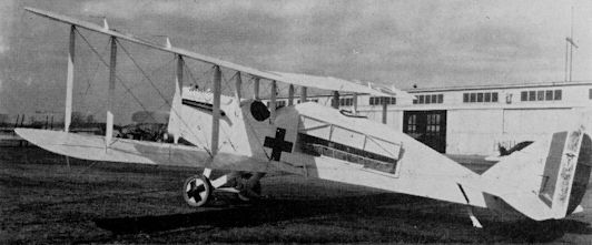
Since the United States had no acceptable military aircraft at the time of her entry into World War I in April 1917, a decision was made to produce proven European types in American factories rather than lose precious time in designing new types without benefit of combat experience. Of several British and French designs selected by the famous Bolling Commission, only one, the de Havilland 4, was built in true production quantities. The British DH-4 was a large all-wood two seater used primarily for observation and light bombing, but its performance with alternative installations of B.H.P. and Rolls-Royce engines was such as to make it an effective two-seat fighter.
A sample British airframe arrived in the U.S. on August 15, 1917, and was rushed by rail to McCook Field, Dayton, Ohio, to test its compatibility with the brand new 400 h.p. Liberty engine which had been developed for it. With the Liberty installed, it first flew at Dayton on October 29, 1917. Following extensive detail redesign to accommodate American production methods, the DH-4, renamed “Liberty Plane” in keeping with the mood of the times (German Sauerkraut had been renamed “Liberty Cabbage” and patriotic citizens were investing their money in “Liberty Bonds”), was placed in production at the Standard Aircraft Corporation of Patterson, New Jersey, the Dayton-Wright Company of Dayton, Ohio, and the Fisher Body Division of General Motors at Cleveland, Ohio. Between them, these plants turned out 4,846 Liberty Planes by the Armistice, comprising 3,106 by Dayton-Wright, 1,600 by Fisher and 140 by Standard. An additional 7,502 on order with these and other firms were cancelled at the end of hostilities.
The American aviation programme of World War I was grossly mis-managed, and there was much public hue and cry, investigation and reorganization. One of the major questions was why an obsolescent model such as the DH-4 should have been selected in the first place. When, after many delays, the Liberties began to arrive in Europe (the first one flying at Romarantin on May 17, 1918, six days after arrival), a new cry arose that America was sending her sons to war in “Flaming Coffins”. This term was originally applied to the Liberty Plane, but was eventually used to designate any obsolete, deficient or outclassed aeroplane.
The American Expeditionary Force in France flew its first sortie over enemy territory with the DH-4 on August 2, 1918, and the Squadrons equipped with the type in France comprised Nos. 8, 11, 20, 50, 85, 96, 100, 135, 155, 166, 168, 278 and 354.
Combat deficiencies of the American model soon became apparent, notably the tendency of the machine to catch fire in the air without assistance from the enemy and the exposed position of the supposedly self-sealing fuel tank, located, as on the British model, between the pilot and observer. With the heavy tank behind him, the pilot was an almost certain fatality in any crash. Another undesirable characteristic was a tendency to nose over during landings on soft or muddy fields. Some intrepid observers took effective countermeasures by leaving their seats and crawling aft on top of the fuselage during landings to decrease the nose heaviness. Effective as this method was, it became the subject of severe official criticism in reports of Liberty Plane performance.
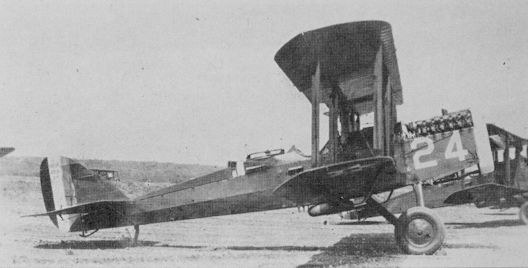
Some of the complaints were heard in the right places, and extensive redesign resulted in the DH-4B, featuring a re-located landing gear and revised cockpit arrangement with the pilot behind the tank and close to the observer as in the newer British DH-9. Fuselage construction was changed to one continuous unit instead of the three-section structure of the original, and the sides were covered with plywood for the full length in place of the fabric between cockpit and tail of the “Liberty Plane”. While 1,213 Liberty Planes were delivered to France, no DH-4Bs were shipped over before the Armistice. With the new model available at home, Army officials saw no point in shipping the notorious “Flaming Coffins” back to America after the Armistice, so those remaining in France were stacked and burned, along with the obsolete observation and trainer types purchased from the French. The resulting “Billion Dollar Bonfire” raised still another hue and cry about American military aircraft procurement policies.
By the end of 1918, an Americanized version of the later British DH-9A was being prepared for production after 13 pilot models had been started by the Army Engineering Division and Dayton-Wright as USD-9 and 9A. Production was cancelled by the Armistice and post-war requirements were met by existing DH-4s and 4Bs.
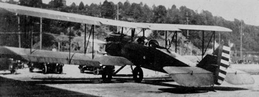
While even the revised DH-4B was obsolete in the early post-war years, there were no funds available for the development or procurement of new types. However, “maintenance” funds were available, and these, carefully distributed, kept the struggling American aircraft industry alive during the critical post-war years through extensive modification and rebuilding, starting with the conversion of Liberty Planes to DH-4Bs. This programme, in which at least ten companies and Army depots participated, culminated in the Atlantic (Fokker) and Boeing-built DH-4Ms of 1923/24. These utilized the wings, tails, power plants and other hardware of existing DH-4Bs but featured new fuselages of welded steel tube construction as developed by Fokker during the war. The “M” in the designation stood for “modernized”.
By the time the Ms were built, new designs had become available, but the old biplanes were kept in service because an enormous investment had been made in them and the taxpayers would not stand for any more bonfires just because the aeroplanes were obsolete. As a result, the last DH-4M-2P was not retired from Army service until 1932.
Because of their carefully recorded performance and ready availability, the DHs were widely used for experimental and test flying at McCook Field, Headquarters of the Air Service Engineering Division, for several years after the War. All sorts of in-line and radial power plants were installed, new wings of various sizes and airfoils were tried, and some of the open-cockpit designs were converted to cabin types.
A number of DH-4Bs were fitted experimentally with Loening COA-1 wings and placed in limited service status. Attempts to extend the service utilization of the basic DH-4 through the use of new wings culminated in the Boeing XCO-7, XCO-7A and XCO-7B (24452/24454) which were standard DH-4M1 fuselages fitted with entirely new thick- section tapered wings, enlarged horizontal tail surfaces, and divided oleo-pneumatic landing gear. The XCO-7B was the most distinctive, featuring an experimental inverted air-cooled Liberty engine. The performance improvement was not sufficient to justify manufacture of the new wings.
An Atlantic-built DH-4M2 became XCO-8 (23163) when fitted with the Loening wings and achieved a degree of fame when used by Captain O. A. Stevens for experiments in high-altitude and long-range photography through 1930. Flight refuelling trials were made in 1923 with a DH-4 receiver, carrying an extra fuel tank, with a large filling point, in the rear fuselage; and the DH-4B-1 tanker which trailed a 50 ft. length of hose with a quick-acting shut-off valve. The first successful contacts were made on June 27, 1923, and on August 27/28, the receiver remained airborne for 37 hours 15 minutes in the first conclusive demonstration of flight refuelling.
While the Liberty Planes and DH-4Bs were originally identified only by their DH-4/DH-4B designations regardless of various minor modifications or change of mission, the original manufacturer’s model designation was treated as an official type number after adoption of the letter-and-number system in 1920. Originally, suffix letters were added to indicate straight sequence of design development but other letter-and-number suffixes were added to indicate special purpose modifications or usage of the aeroplanes. In the normal course of reassignment and modification, it was not unusual for one airframe to have carried several different designations throughout its service life. The DHs are impossible to keep track of by serial number, partly because of the incompleteness of the early records and partly because of the practice, not followed consistently, of assigning a new serial number at the time an aeroplane was rebuilt. Some DHs are known to have carried as many as four, the latest being two assigned in 1926 (DH-4BK, 26-29/30).
The following is a partial listing of “Standard” designations officially assigned to DH-4 variants between 1920 and 1925 and includes a few of the purely experimental designations assigned to various research and development models at McCook Field.
DH-4, DH-4B VARIANTS
DH-4 Basic Americanized “Liberty Plane” of World War I.
DH-4A Single Liberty with revised fuel system, 110 gallon tank; British three-seater.
DH-4Amb-1, Amb-2 One and two-litter ambulance conversions, respectively.
DH-4Ard Dual-control cross-country version, 165 gallon tank, 7 hour fuel supply as modified at Ardmont Repair Depot, Montgomery, Alabama.
DH-4B Major redesign of DH-4; 88 gallon main tank, 8 gallon reserve.
DH-4B1 110 gallon main tank, 8 gallon reserve.
DH-4B2 76 gallon leak-proof tank, 8 gallon reserve.
DH-4B3 135 gallon main tank, 8 gallon reserve.
DH-4B4 Airways Version, 110 gallon main tank, 8 gallon reserve.
DH-4B5 “Honeymoon Express”, 2-seat cabin behind pilot as British DH-4A.
DH-4BD Standard DH-4B equipped for crop dusting.
DH-4BG Gas Barrage conversion with chemical smoke tanks.
DH-4BK Standard DH-4B equipped for night flying.
DH-4BM Messenger with rear seat and rear baggage compartment only.
DH-4BM1 Dual-control transport version of DH-4BM, with 110 gallon main tank.
DH-4BM2 As DH-4BM1 Transport version with 135 gallon main tank.
XDH-4BP Experimental single-seat photo plane - cameras in front cockpit.
DH-4BP1 Peacetime photo plane for vertical mapping, oblique and motion pictures.
XDH-4BP2 Experimental photo plane - 135 gallon tank, USD-9 A wings.
DH-4BP3 Similar to DH-4BP1, 110 gallon main tank.
XDH-4BS Experimental DH-4B with supercharger, 88 gallon main tank.
DH-4BT DH-4B modified as dual control trainer with instruments in rear cockpit.
DH-4BW Test bed for 300 h.p. Wright-Hispano “H” engine.
DH-4C DH-4B test bed for 350 h.p. Packard 1A-1237 engine, modified fuselage.
XDH-4L Cleaned-up cross-country racer, 185 gallon, 9 hour fuel supply.
DH-4M VARIANTS
DH-4M “Modernized” DH-4/DH-4B with new steel tube fuselage. 53 built by Boeing.
DH-4M1 Boeing-built DH-4M, 76 gallon main tank, arc-welded fuselage. 97 built.
DH-4M1K DH-4M1 equipped as target tug.
DH-4M1T Dual-control trainer version.
DH-4M2 Atlantic-built (Fokker) DH-4M, 110 gallon main tank, gas-welded fuselage. 135 built.
DH-4M2A Equipped for operation on airways.
DH-4M2K Target tug.
DH-4M2P Photo plane with 110 gallon main tank.
DH-4M2S Supercharged engine, 88 gallon main tank.
DH-4M2T Dual control trainer, no armament or radio.
Another line of DH-4 development was started by the U.S. Post Office Department in cooperation with the Engineering Division of the Air Service. The DH-4B was standardized for mail service in 1919, and entered service with little modification other than pilot control from the rear cockpit and a 400 lb. capacity mail compartment replacing the forward cockpit. Standard Air Service colouring, markings, and serial numbers were used to about 1923. The Airmail DH-4 soon developed into a standardized postal configuration, however, with modified landing gear, enlarged rudder, clear-varnished plywood-sided fuselage, and a rounded turtledeck similar to that of the Army “Airways” DH-4B. This configuration was to remain standard for virtually all U.S. civil mailplane designs through the Northrop “Gamma” of 1932, prototype of the Army YA-13/XA-16 attack models.
When the government abandoned the airmail routes to private operators in July 1927, 15 airmail DH-4s in the Post Office serial number range of 328/427 were turned over to the Army. Useless for normal military purposes, they were reconverted to two-seaters and used for the Air Corps forest fire patrols in the western states. Since they were not standard purchases, they did not acquire 1927 fiscal serial numbers but merely added the prefix A.C. to the Post Office number, a safe enough procedure since earlier Army models in that serial range were long gone. Standard Army colouring was not applied, either, and the patrol models flew with the airmail silver wings and varnished fuselages. The only markings were U.S. Army and the serial number on the fuselages. These repossessed DHs remained in service until 1931.
The most distinctive of all the many DH-4 variants was the twin-engine model developed in 1919 by Lowe, Willard, and Fowler (L.W.F.) for the Post Office. The single Liberty was removed in favour of increased mail capacity and two 200 h.p. Hall-Scott L-6 engines were installed between the wings. Two extra rudders were required because of the altered air-stream. Twenty were built for the Post Office, and ten more for the Army. Other modifications such as Loening and Bellanca wings, increased wingspans, deep-belly fuselages, etc., were tested on airmail DH-4s at McCook Field but were not adopted.
TECHNICAL DATA (DH-4)
MANUFACTURER: (DH-4): Dayton-Wright Co., Dayton, Ohio; Standard Aircraft Corp., Patterson, N.J.; Fisher Body Division of General Motors, Cleveland, Ohio. (DH-4M): Boeing Airplane Co., Seattle and Atlantic Aircraft Corp., Teterboro, N.J. TYPE: Observation and day bomber.
ACCOMMODATION: Pilot and observer in tandem.
Since the United States had no acceptable military aircraft at the time of her entry into World War I in April 1917, a decision was made to produce proven European types in American factories rather than lose precious time in designing new types without benefit of combat experience. Of several British and French designs selected by the famous Bolling Commission, only one, the de Havilland 4, was built in true production quantities. The British DH-4 was a large all-wood two seater used primarily for observation and light bombing, but its performance with alternative installations of B.H.P. and Rolls-Royce engines was such as to make it an effective two-seat fighter.
A sample British airframe arrived in the U.S. on August 15, 1917, and was rushed by rail to McCook Field, Dayton, Ohio, to test its compatibility with the brand new 400 h.p. Liberty engine which had been developed for it. With the Liberty installed, it first flew at Dayton on October 29, 1917. Following extensive detail redesign to accommodate American production methods, the DH-4, renamed “Liberty Plane” in keeping with the mood of the times (German Sauerkraut had been renamed “Liberty Cabbage” and patriotic citizens were investing their money in “Liberty Bonds”), was placed in production at the Standard Aircraft Corporation of Patterson, New Jersey, the Dayton-Wright Company of Dayton, Ohio, and the Fisher Body Division of General Motors at Cleveland, Ohio. Between them, these plants turned out 4,846 Liberty Planes by the Armistice, comprising 3,106 by Dayton-Wright, 1,600 by Fisher and 140 by Standard. An additional 7,502 on order with these and other firms were cancelled at the end of hostilities.
The American aviation programme of World War I was grossly mis-managed, and there was much public hue and cry, investigation and reorganization. One of the major questions was why an obsolescent model such as the DH-4 should have been selected in the first place. When, after many delays, the Liberties began to arrive in Europe (the first one flying at Romarantin on May 17, 1918, six days after arrival), a new cry arose that America was sending her sons to war in “Flaming Coffins”. This term was originally applied to the Liberty Plane, but was eventually used to designate any obsolete, deficient or outclassed aeroplane.
The American Expeditionary Force in France flew its first sortie over enemy territory with the DH-4 on August 2, 1918, and the Squadrons equipped with the type in France comprised Nos. 8, 11, 20, 50, 85, 96, 100, 135, 155, 166, 168, 278 and 354.
Combat deficiencies of the American model soon became apparent, notably the tendency of the machine to catch fire in the air without assistance from the enemy and the exposed position of the supposedly self-sealing fuel tank, located, as on the British model, between the pilot and observer. With the heavy tank behind him, the pilot was an almost certain fatality in any crash. Another undesirable characteristic was a tendency to nose over during landings on soft or muddy fields. Some intrepid observers took effective countermeasures by leaving their seats and crawling aft on top of the fuselage during landings to decrease the nose heaviness. Effective as this method was, it became the subject of severe official criticism in reports of Liberty Plane performance.
Some of the complaints were heard in the right places, and extensive redesign resulted in the DH-4B, featuring a re-located landing gear and revised cockpit arrangement with the pilot behind the tank and close to the observer as in the newer British DH-9. Fuselage construction was changed to one continuous unit instead of the three-section structure of the original, and the sides were covered with plywood for the full length in place of the fabric between cockpit and tail of the “Liberty Plane”. While 1,213 Liberty Planes were delivered to France, no DH-4Bs were shipped over before the Armistice. With the new model available at home, Army officials saw no point in shipping the notorious “Flaming Coffins” back to America after the Armistice, so those remaining in France were stacked and burned, along with the obsolete observation and trainer types purchased from the French. The resulting “Billion Dollar Bonfire” raised still another hue and cry about American military aircraft procurement policies.
By the end of 1918, an Americanized version of the later British DH-9A was being prepared for production after 13 pilot models had been started by the Army Engineering Division and Dayton-Wright as USD-9 and 9A. Production was cancelled by the Armistice and post-war requirements were met by existing DH-4s and 4Bs.
While even the revised DH-4B was obsolete in the early post-war years, there were no funds available for the development or procurement of new types. However, “maintenance” funds were available, and these, carefully distributed, kept the struggling American aircraft industry alive during the critical post-war years through extensive modification and rebuilding, starting with the conversion of Liberty Planes to DH-4Bs. This programme, in which at least ten companies and Army depots participated, culminated in the Atlantic (Fokker) and Boeing-built DH-4Ms of 1923/24. These utilized the wings, tails, power plants and other hardware of existing DH-4Bs but featured new fuselages of welded steel tube construction as developed by Fokker during the war. The “M” in the designation stood for “modernized”.
By the time the Ms were built, new designs had become available, but the old biplanes were kept in service because an enormous investment had been made in them and the taxpayers would not stand for any more bonfires just because the aeroplanes were obsolete. As a result, the last DH-4M-2P was not retired from Army service until 1932.
Because of their carefully recorded performance and ready availability, the DHs were widely used for experimental and test flying at McCook Field, Headquarters of the Air Service Engineering Division, for several years after the War. All sorts of in-line and radial power plants were installed, new wings of various sizes and airfoils were tried, and some of the open-cockpit designs were converted to cabin types.
A number of DH-4Bs were fitted experimentally with Loening COA-1 wings and placed in limited service status. Attempts to extend the service utilization of the basic DH-4 through the use of new wings culminated in the Boeing XCO-7, XCO-7A and XCO-7B (24452/24454) which were standard DH-4M1 fuselages fitted with entirely new thick- section tapered wings, enlarged horizontal tail surfaces, and divided oleo-pneumatic landing gear. The XCO-7B was the most distinctive, featuring an experimental inverted air-cooled Liberty engine. The performance improvement was not sufficient to justify manufacture of the new wings.
An Atlantic-built DH-4M2 became XCO-8 (23163) when fitted with the Loening wings and achieved a degree of fame when used by Captain O. A. Stevens for experiments in high-altitude and long-range photography through 1930. Flight refuelling trials were made in 1923 with a DH-4 receiver, carrying an extra fuel tank, with a large filling point, in the rear fuselage; and the DH-4B-1 tanker which trailed a 50 ft. length of hose with a quick-acting shut-off valve. The first successful contacts were made on June 27, 1923, and on August 27/28, the receiver remained airborne for 37 hours 15 minutes in the first conclusive demonstration of flight refuelling.
While the Liberty Planes and DH-4Bs were originally identified only by their DH-4/DH-4B designations regardless of various minor modifications or change of mission, the original manufacturer’s model designation was treated as an official type number after adoption of the letter-and-number system in 1920. Originally, suffix letters were added to indicate straight sequence of design development but other letter-and-number suffixes were added to indicate special purpose modifications or usage of the aeroplanes. In the normal course of reassignment and modification, it was not unusual for one airframe to have carried several different designations throughout its service life. The DHs are impossible to keep track of by serial number, partly because of the incompleteness of the early records and partly because of the practice, not followed consistently, of assigning a new serial number at the time an aeroplane was rebuilt. Some DHs are known to have carried as many as four, the latest being two assigned in 1926 (DH-4BK, 26-29/30).
The following is a partial listing of “Standard” designations officially assigned to DH-4 variants between 1920 and 1925 and includes a few of the purely experimental designations assigned to various research and development models at McCook Field.
DH-4, DH-4B VARIANTS
DH-4 Basic Americanized “Liberty Plane” of World War I.
DH-4A Single Liberty with revised fuel system, 110 gallon tank; British three-seater.
DH-4Amb-1, Amb-2 One and two-litter ambulance conversions, respectively.
DH-4Ard Dual-control cross-country version, 165 gallon tank, 7 hour fuel supply as modified at Ardmont Repair Depot, Montgomery, Alabama.
DH-4B Major redesign of DH-4; 88 gallon main tank, 8 gallon reserve.
DH-4B1 110 gallon main tank, 8 gallon reserve.
DH-4B2 76 gallon leak-proof tank, 8 gallon reserve.
DH-4B3 135 gallon main tank, 8 gallon reserve.
DH-4B4 Airways Version, 110 gallon main tank, 8 gallon reserve.
DH-4B5 “Honeymoon Express”, 2-seat cabin behind pilot as British DH-4A.
DH-4BD Standard DH-4B equipped for crop dusting.
DH-4BG Gas Barrage conversion with chemical smoke tanks.
DH-4BK Standard DH-4B equipped for night flying.
DH-4BM Messenger with rear seat and rear baggage compartment only.
DH-4BM1 Dual-control transport version of DH-4BM, with 110 gallon main tank.
DH-4BM2 As DH-4BM1 Transport version with 135 gallon main tank.
XDH-4BP Experimental single-seat photo plane - cameras in front cockpit.
DH-4BP1 Peacetime photo plane for vertical mapping, oblique and motion pictures.
XDH-4BP2 Experimental photo plane - 135 gallon tank, USD-9 A wings.
DH-4BP3 Similar to DH-4BP1, 110 gallon main tank.
XDH-4BS Experimental DH-4B with supercharger, 88 gallon main tank.
DH-4BT DH-4B modified as dual control trainer with instruments in rear cockpit.
DH-4BW Test bed for 300 h.p. Wright-Hispano “H” engine.
DH-4C DH-4B test bed for 350 h.p. Packard 1A-1237 engine, modified fuselage.
XDH-4L Cleaned-up cross-country racer, 185 gallon, 9 hour fuel supply.
DH-4M VARIANTS
DH-4M “Modernized” DH-4/DH-4B with new steel tube fuselage. 53 built by Boeing.
DH-4M1 Boeing-built DH-4M, 76 gallon main tank, arc-welded fuselage. 97 built.
DH-4M1K DH-4M1 equipped as target tug.
DH-4M1T Dual-control trainer version.
DH-4M2 Atlantic-built (Fokker) DH-4M, 110 gallon main tank, gas-welded fuselage. 135 built.
DH-4M2A Equipped for operation on airways.
DH-4M2K Target tug.
DH-4M2P Photo plane with 110 gallon main tank.
DH-4M2S Supercharged engine, 88 gallon main tank.
DH-4M2T Dual control trainer, no armament or radio.
Another line of DH-4 development was started by the U.S. Post Office Department in cooperation with the Engineering Division of the Air Service. The DH-4B was standardized for mail service in 1919, and entered service with little modification other than pilot control from the rear cockpit and a 400 lb. capacity mail compartment replacing the forward cockpit. Standard Air Service colouring, markings, and serial numbers were used to about 1923. The Airmail DH-4 soon developed into a standardized postal configuration, however, with modified landing gear, enlarged rudder, clear-varnished plywood-sided fuselage, and a rounded turtledeck similar to that of the Army “Airways” DH-4B. This configuration was to remain standard for virtually all U.S. civil mailplane designs through the Northrop “Gamma” of 1932, prototype of the Army YA-13/XA-16 attack models.
When the government abandoned the airmail routes to private operators in July 1927, 15 airmail DH-4s in the Post Office serial number range of 328/427 were turned over to the Army. Useless for normal military purposes, they were reconverted to two-seaters and used for the Air Corps forest fire patrols in the western states. Since they were not standard purchases, they did not acquire 1927 fiscal serial numbers but merely added the prefix A.C. to the Post Office number, a safe enough procedure since earlier Army models in that serial range were long gone. Standard Army colouring was not applied, either, and the patrol models flew with the airmail silver wings and varnished fuselages. The only markings were U.S. Army and the serial number on the fuselages. These repossessed DHs remained in service until 1931.
The most distinctive of all the many DH-4 variants was the twin-engine model developed in 1919 by Lowe, Willard, and Fowler (L.W.F.) for the Post Office. The single Liberty was removed in favour of increased mail capacity and two 200 h.p. Hall-Scott L-6 engines were installed between the wings. Two extra rudders were required because of the altered air-stream. Twenty were built for the Post Office, and ten more for the Army. Other modifications such as Loening and Bellanca wings, increased wingspans, deep-belly fuselages, etc., were tested on airmail DH-4s at McCook Field but were not adopted.
TECHNICAL DATA (DH-4)
MANUFACTURER: (DH-4): Dayton-Wright Co., Dayton, Ohio; Standard Aircraft Corp., Patterson, N.J.; Fisher Body Division of General Motors, Cleveland, Ohio. (DH-4M): Boeing Airplane Co., Seattle and Atlantic Aircraft Corp., Teterboro, N.J. TYPE: Observation and day bomber.
ACCOMMODATION: Pilot and observer in tandem.

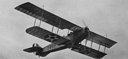
De Havilland DH-4 in early production colours
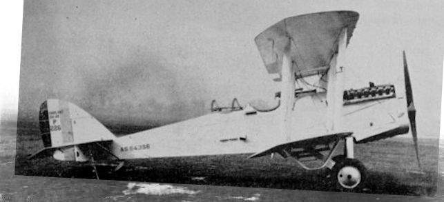
U.S. Army Air Corps DH-4B serial A.S.64356 (McCook Field project number P226), showing the revised cockpit position an d oversize wheels.
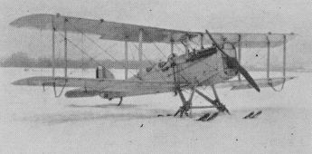
DH-4B-4 on skis
De Havilland DH-4Amb-2 to carry two stretchers
The metal fuselaged DH-4 was identified by prominent fuselage stringers. This example, a Boeing-built DH-4M-1, carried U.S. Army Air Corps serial A.S31202, with spare wheel under fuselage
Atlantic XCO-8 with Loening COA-1 wing

Boeing XCO-7A

De Havilland Twin DH-4 for the Post Office
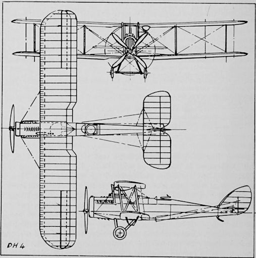
DH 4
ENGINEERING DIVISION USD-9
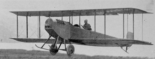
The USD-9 was an American redesign of the British DH-9 in the same manner that the “Liberty Plane” was an Americanization of the original DH-4. Principal outward difference between the -4 and -9 was the relocation of the pilot’s cockpit, which was moved aft while the fuel tank, originally between the cockpits, was moved forward. All USD-9s as well as 9As used the Liberty. The Armistice ended production after nine had been built at McCook Field (40060/40068) and four by Dayton Wright (40044, 40118, 40119 plus one).
Span, 46 ft.; length, 30 ft. 2 7/8 in.; wing area, 508 sq. ft.; empty weight, 2,815 lb.; gross weight, 4,322 lb.; high speed, 126 m.p.h.
ENGINEERING DIVISION USD-9
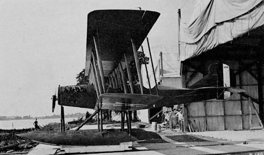
STANDARD/HANDLEY-PAGE O-400
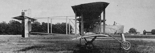
The Standard Aircraft Corporation of Elizabeth, N.J., was chosen in 1917 to build the Handley-Page O-400, and to deliver sets of components for assembly in England. The first set was assembled in the U.S. by Standard, fitted with Liberty engines, and christened “Langley” in July 1918 for publicity purposes. By war’s end, sets of spares equivalent to over 100 complete O-400s had been delivered. After the Armistice, eight Liberty-powered O-400s (inc. 62445-62451) were assembled for the U.S. Army.
Span, 100 ft.; length, 62 ft. 10 in.; wing area, 1,655 sq. ft.; empty weight, 8,721 lb.; gross weight, 12,425 lb.; high speed, 96 m.p.h.

STANDARD/HANDLEY-PAGE O-400
R.A.E. F.E.2B
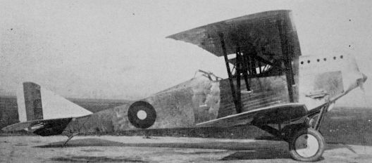
The F.E.2 was another pre-war official British design. The initials were originally considered to stand for “Farman Experimental” to associate the pusher configuration with the contemporary French Farman pushers. These letters later stood for “Fighting Experimental”. The “Fee’s” were used into 1918 as bombers and observation planes. The A.E.F. bought 30 F.E.2Bs powered with 160-h.p. Beardmore engines for training in England.
Span, 47 ft. 9 in.; length, 32 ft. 3 in.; wing area, 494 sq. ft.; gross weight, 3,037 lb.; high speed, 91 m.p.h.
R.A.E. B.E.2E
The B.E.2 series was introduced by the British Royal Aircraft Factory (later Establishment, or R.A.E.) in 1912. The B.E.2E, of which 12 were bought by the A.E.F. for training in England, differed from early versions in having modified wings with a single bay of struts and extensive overhang on the upper instead of two-bay equal-span wings. Power plant was a 90 h.p. R.A.E. 1A air-cooled V-8 engine.
Span, 40 ft. 9 in.; length, 27 ft. 3 in.; wing area, 360 sq. ft.; gross weight, 2,100 lb.; high speed, 90 m.p.h.
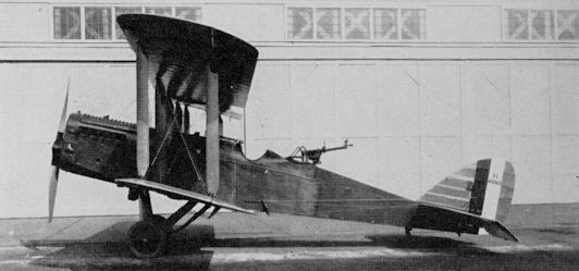
CURTISS S.E.5A/EBERHART S.E.5E
One of the best known designs selected by the Bolling Commission for U.S. production was the S.E.5A, designed by H. P. Folland in Britain. Planned mass production by Curtiss did not materialize but the company modified and assembled 57 British-built airframes (which retained their British serials). In 1922 and 1923, the Eberhart Steel Products Co. rebuilt 50 S.E.s with 180-h.p. Wright-Hispano Es for use as advanced trainers under the designation of S.E.5E (22-276/325)
Span, 26 ft. 9 in.; length, 20 ft. 10 in.; area, 247 sq. ft.; weight, 2,060 lb.; high speed, 122 m.p.h.
One of 50 S.E.5a’s, rebuilt in the US by Eberhart as S.E.5E’s with Wright-Hispano E engines.
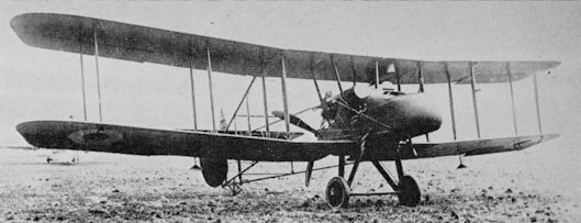
SOPWITH 1A2
The Sopwith “1-1/2- Strutter”, so named by the British because of its extra centre section struts, was a notable military aircraft before American entry into World War I. The French obtained large quantities of the two-seat observation version, which they named Sopwith 1A2, and the single-seat bomber version 1B1, by purchase and license manufacture. When the A.E.F. desperately needed aeroplanes in 1917/18, the French sold 514 Sopwiths (384 As and 130 Bs) to the Americans.
Span, 33 ft. 6 in.; length, 25 ft. 4 in.; area, 353 sq, ft.; weight, 2,061 lb.; speed, 95 m.p.h.

Sopwith 1 1/2 Strutter with the USAS.
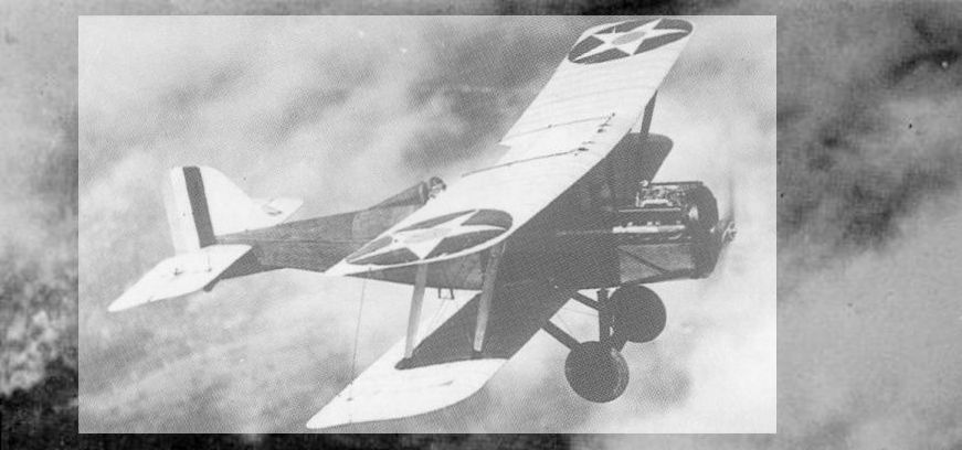
SOPWITH CAMEL
Because of the American shortage of combat aircraft in 1918, 143 Camels powered with 130-h.p. Clerget rotary engines were purchased in England. The majority of these were used as advanced trainers although some were intended to be night fighters. Only one A.E.F. squadron had them at the front at the time of the Armistice, and then only a few. The A.E.F. Camels flew with non-standard markings in that the British roundels, including fuselage marking and white outlining rings, were merely painted over with the colours in the American order, as illustrated.
Because of the American shortage of combat aircraft in 1918, 143 Camels powered with 130-h.p. Clerget rotary engines were purchased in England. The majority of these were used as advanced trainers although some were intended to be night fighters. Only one A.E.F. squadron had them at the front at the time of the Armistice, and then only a few. The A.E.F. Camels flew with non-standard markings in that the British roundels, including fuselage marking and white outlining rings, were merely painted over with the colours in the American order, as illustrated.
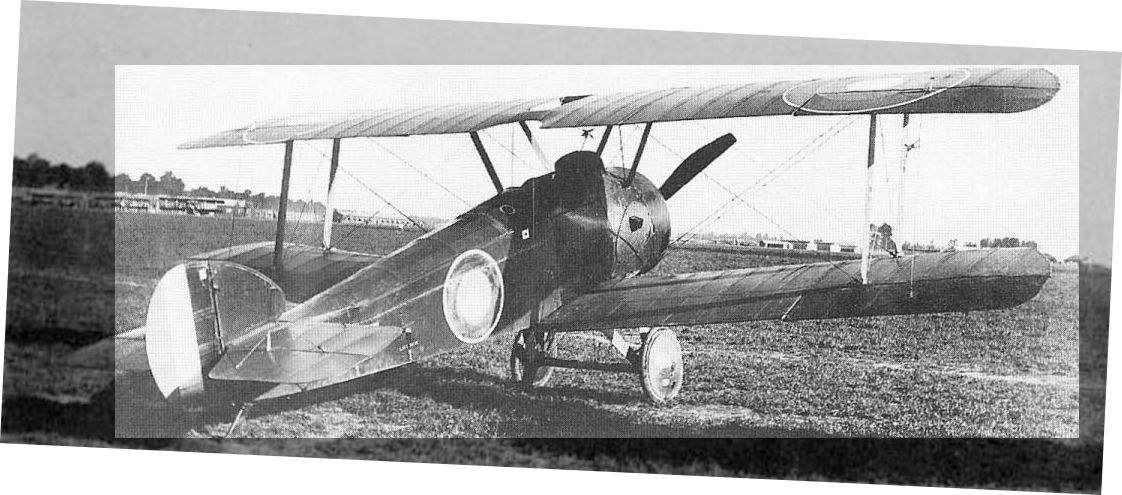
A Navy Sopwith Camel in France.
ANSALDO S.V.A.-10
The S.V.A. 9 and 10 were two-seat versions of the famous S.V.A. (Societa Verduzio Ansaldo) 5, the outstanding Italian fighter of World War I. Unique features of the basic design were the Warren truss bracing of the wings and the abrupt changes in cross section of the plywood fuselage, which became triangular aft of the cockpit. One S.V.A.-5 was sent to the U.S. for test in 1917, and at least one S.V.A.-10 was purchased after the Armistice for use of the American Air Attache in Rome.
The S.V.A. 9 and 10 were two-seat versions of the famous S.V.A. (Societa Verduzio Ansaldo) 5, the outstanding Italian fighter of World War I. Unique features of the basic design were the Warren truss bracing of the wings and the abrupt changes in cross section of the plywood fuselage, which became triangular aft of the cockpit. One S.V.A.-5 was sent to the U.S. for test in 1917, and at least one S.V.A.-10 was purchased after the Armistice for use of the American Air Attache in Rome.
ANSALDO S.V.A.-10
STANDARD/CAPRONI
In addition to French and British designs, the unique twin-fuselage trimotor Italian Caproni biplane and triplane bombers were also selected for production in America in 1917/1918, by the Standard Aircraft Corp. of Elizabeth, N.J., and the Fisher Body Works of Cleveland, Ohio. By war’s end, only two Capronis had been built by Standard (40070, 40071) and one (42119), which was not accepted, by Fisher. Two Italian-built samples were sent to America, and the U.S. Forces in France obtained at least one other from the French.
Span, 76 ft. 10 in.; length, 41 ft. 2 in.; wing area, 1,420 sq. ft.; empty weight, 7,700 lb.; gross weight, 12,350 lb.; high speed, 103 m.p.h.

STANDARD/CAPRONI
S.I.A. 7B
In 1917, the Italian Government sent a pair of S.I.A. 7B reconnaissance-bombers to the United States for evaluation and consideration for production under the prevailing plan to mass-produce established European designs. Developed by the Societe Italiano Aviazione of Turin, the S.I.A. 7B was powered with a 300-h.p. Fiat engine and used the standard Italian structural feature of plywood-covered fuselage. The 7B was not put into production in the U.S. but 19 were bought in Italy for use by A.E.F. units sent there.
Span, 43 ft. 8 in.; length, 29 ft. 9 in.; wing area, 460 sq. ft.; gross weight, 3,454 lb.; high speed, 111 m.p.h.
BREESE PENGUIN
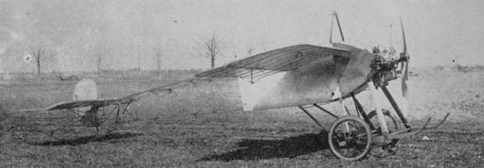
The Breese Penguin was built to apply the peculiar French technique of pre-flight ground training to the admirably suited open Texas Prairies. The aircraft used, called “Roleurs” by the French, were low-powered machines with normal aeroplane features except that the wings were too small to permit flight. They got up enough speed, however, for the student to raise the tail and get the “feel” of the controls. The Breese and the ground-running method were not adopted, possibly due to the roughrunning 28-h.p. Lawrence two-cylinder engine, and 296 of the 301 “Penguins” (inc. 33475/33759) were placed in storage until after the war.
The Breese Penguin was built to apply the peculiar French technique of pre-flight ground training to the admirably suited open Texas Prairies. The aircraft used, called “Roleurs” by the French, were low-powered machines with normal aeroplane features except that the wings were too small to permit flight. They got up enough speed, however, for the student to raise the tail and get the “feel” of the controls. The Breese and the ground-running method were not adopted, possibly due to the roughrunning 28-h.p. Lawrence two-cylinder engine, and 296 of the 301 “Penguins” (inc. 33475/33759) were placed in storage until after the war.
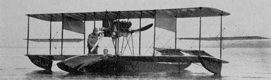
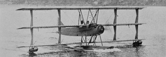
BURGESS H
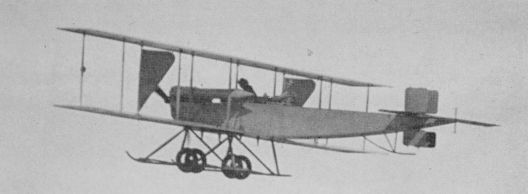
Seven Burgess Model H trainers were bought in 1912 as the Army’s first tractor designs. Three were converted to seaplanes by removing the wheels from the combination skid-wheel undercarriage and bolting twin pontoons to the skids. The Burgess Hs retained many earlier Wright features, notably the warping-wing method of lateral control and the Wright Model B type of landing gear. The skid under the twin rudders was merely to protect them, and not a true tailskid. The Hs were troublesome, and along with the Wright and Curtiss pushers, gave the Army Training School at North Island, San Diego, a bad reputation.
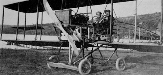
Four Burgess Hs (Serials 24, 28 and two others) were redesigned and rebuilt by Grover C. Loening, at San Diego. The 70 h.p. French Renault engine was retained, as was the basic fuselage. The wings were rebuilt to use aileron control, and the Wright control levers were replaced by Curtiss controls with wheel for rudder and shoulder yoke for the ailerons. The new tail used a single enlarged rudder with fixed vertical fin and the skid-type landing gear was replaced by an entirely new cross-axle type that Loening patented and which in its essential form was used on all subsequent American designs.
The rebuilt Burgess H No. 28, fitted with extra tanks and flown by student Q. B. Jones, set a world’s endurance record for three persons of 7 hours 5 minutes on March 12, 1915.
Seven Burgess Model H trainers were bought in 1912 as the Army’s first tractor designs. Three were converted to seaplanes by removing the wheels from the combination skid-wheel undercarriage and bolting twin pontoons to the skids. The Burgess Hs retained many earlier Wright features, notably the warping-wing method of lateral control and the Wright Model B type of landing gear. The skid under the twin rudders was merely to protect them, and not a true tailskid. The Hs were troublesome, and along with the Wright and Curtiss pushers, gave the Army Training School at North Island, San Diego, a bad reputation.
Four Burgess Hs (Serials 24, 28 and two others) were redesigned and rebuilt by Grover C. Loening, at San Diego. The 70 h.p. French Renault engine was retained, as was the basic fuselage. The wings were rebuilt to use aileron control, and the Wright control levers were replaced by Curtiss controls with wheel for rudder and shoulder yoke for the ailerons. The new tail used a single enlarged rudder with fixed vertical fin and the skid-type landing gear was replaced by an entirely new cross-axle type that Loening patented and which in its essential form was used on all subsequent American designs.
The rebuilt Burgess H No. 28, fitted with extra tanks and flown by student Q. B. Jones, set a world’s endurance record for three persons of 7 hours 5 minutes on March 12, 1915.
Modified Burgess H
BURGESS I SCOUT
In 1910, the W. Starling Burgess Co. of Marblehead, Mass., a manufacturer of speedboats, produced a Curtiss pusher type seaplane with the assistance of Greely S. Curtis (no relation of Glenn H. Curtiss). The success of this machine encouraged further activity, and the firm obtained a licence to build established Wright designs, starting with the Models B and C (respectively Burgess Models F and J, Army Serials 11 and 18). The 1913 Burgess Model I (serial 17) illustrated above was a single example for the Army using Wright features and a single 60 h.p. Sturtevant engine. The I was used as a scout in the Philippines and crashed in 1915. Span 39 ft. 10 in.; length 31 ft. 4 in.; gross weight, 2,038 lb.; speed, 59 m.p.h.; rate of climb 210 ft./min.
In 1910, the W. Starling Burgess Co. of Marblehead, Mass., a manufacturer of speedboats, produced a Curtiss pusher type seaplane with the assistance of Greely S. Curtis (no relation of Glenn H. Curtiss). The success of this machine encouraged further activity, and the firm obtained a licence to build established Wright designs, starting with the Models B and C (respectively Burgess Models F and J, Army Serials 11 and 18). The 1913 Burgess Model I (serial 17) illustrated above was a single example for the Army using Wright features and a single 60 h.p. Sturtevant engine. The I was used as a scout in the Philippines and crashed in 1915. Span 39 ft. 10 in.; length 31 ft. 4 in.; gross weight, 2,038 lb.; speed, 59 m.p.h.; rate of climb 210 ft./min.
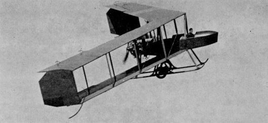
BURGESS-DUNNE TAILLESS
The Dunne Tailless biplane developed in England was manufactured in the U.S. by the Burgess Company of Marblehead, Massachusetts. A single landplane example (serial 36) was evaluated by the Army at North Island, San Diego. Powered by a 200-h.p. water-cooled Canton-Unne radial engine the Burgess-Dunne achieved longitudinal stability by extreme sweepback of the wings, which put the elevators an effective distance aft of the centre of gravity. The control system used two levers; moved together, they raised or lowered the elevators, moved differentially, they turned the machine right or left through aileron action. Span 46 ft. 6 in.; length, 23 ft.
The Dunne Tailless biplane developed in England was manufactured in the U.S. by the Burgess Company of Marblehead, Massachusetts. A single landplane example (serial 36) was evaluated by the Army at North Island, San Diego. Powered by a 200-h.p. water-cooled Canton-Unne radial engine the Burgess-Dunne achieved longitudinal stability by extreme sweepback of the wings, which put the elevators an effective distance aft of the centre of gravity. The control system used two levers; moved together, they raised or lowered the elevators, moved differentially, they turned the machine right or left through aileron action. Span 46 ft. 6 in.; length, 23 ft.
CURTISS D & E
The Army’s second aeroplane was a Curtiss Model D, similar to the standard Curtiss pusher with tripod landing gear and interplane ailerons then in production. Co-ordinated elevators at both front and rear were a standard feature. The single Army Model D was followed by three improved Model E’s, at least one of which was fitted as a single-pontoon seaplane. One similar Navy model (S/N AH-8, a dual-control trainer) was obtained from the Navy and was still in Army hands in 1919 before being returned. This machine was restored and briefly flown in 1928.
The Army’s second aeroplane was a Curtiss Model D, similar to the standard Curtiss pusher with tripod landing gear and interplane ailerons then in production. Co-ordinated elevators at both front and rear were a standard feature. The single Army Model D was followed by three improved Model E’s, at least one of which was fitted as a single-pontoon seaplane. One similar Navy model (S/N AH-8, a dual-control trainer) was obtained from the Navy and was still in Army hands in 1919 before being returned. This machine was restored and briefly flown in 1928.

Curtiss Model D
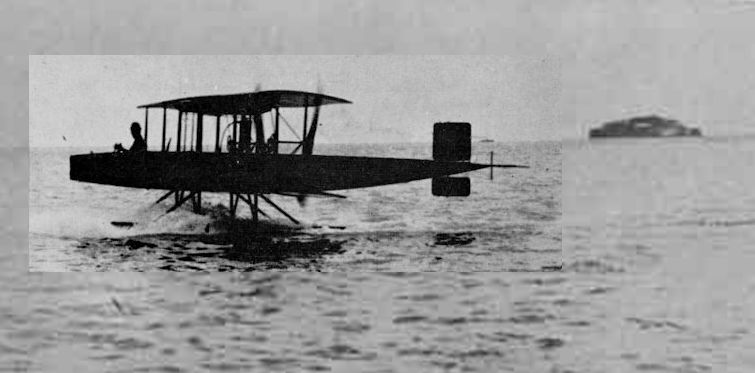
CURTISS F-BOAT
The Curtiss Model F was a single-engined pusher flying boat developed in 1912 and supplied to pre-war private owners as well as to the Army which bought three (15, 34, 49), and the Navy. In keeping with most train¬ers of the 1910/14 era, the F was a side-by-side two seater. The hull was built up of cross-lapped wood veneer strips formed over wooden longerons and bulkheads. Wing details varied between individual machines, some having equal span wings and interplane ailerons while others had an over-hanging upper wing with integral ailerons. Span, 43 ft. 10 in.; length, 27 ft. 9J in.; area 387 sq. ft.; gross weight, 1,860 lbs.; speed, 69 m.p.h.
The Curtiss Model F was a single-engined pusher flying boat developed in 1912 and supplied to pre-war private owners as well as to the Army which bought three (15, 34, 49), and the Navy. In keeping with most train¬ers of the 1910/14 era, the F was a side-by-side two seater. The hull was built up of cross-lapped wood veneer strips formed over wooden longerons and bulkheads. Wing details varied between individual machines, some having equal span wings and interplane ailerons while others had an over-hanging upper wing with integral ailerons. Span, 43 ft. 10 in.; length, 27 ft. 9J in.; area 387 sq. ft.; gross weight, 1,860 lbs.; speed, 69 m.p.h.
The standard Curtiss Model F of 1913 was used by the US Army and Navy, by civil and foreign owners, and remained in production into 1918. This is Anny serial number 34.
CURTISS G TRACTOR
The two 1913 Curtiss Model Gs for the Army (21 and 22) were the first Curtiss tractor designs and the first Curtisses, other than flying boats, to use an enclosed fuselage or hull. The side-by-side two seaters differed considerably in detail, and the first, with a four-wheel landing gear, flew for a while with an uncovered fuselage and was fitted with a direct-drive 80 h.p. Curtiss OX engine (illustrated). The second had tricycle landing gear, enclosed fuselage, and a long dorsal fin. It also had chain reduction gearing to the three-blade propeller. Span, 38 ft. 4 in.; length, 24 ft.; gross weight (No. 22), 1,050 lb.; high speed, 75 m.p.h.; range, 315 miles.
The two 1913 Curtiss Model Gs for the Army (21 and 22) were the first Curtiss tractor designs and the first Curtisses, other than flying boats, to use an enclosed fuselage or hull. The side-by-side two seaters differed considerably in detail, and the first, with a four-wheel landing gear, flew for a while with an uncovered fuselage and was fitted with a direct-drive 80 h.p. Curtiss OX engine (illustrated). The second had tricycle landing gear, enclosed fuselage, and a long dorsal fin. It also had chain reduction gearing to the three-blade propeller. Span, 38 ft. 4 in.; length, 24 ft.; gross weight (No. 22), 1,050 lb.; high speed, 75 m.p.h.; range, 315 miles.
CURTISS J
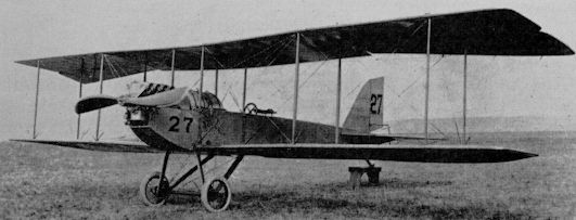
The Model J was the first Curtiss tractor design after the Model G, and the preliminary design was undertaken in England when Glenn Curtiss hired B. Douglas Thomas from Avro. The original version of the J delivered to the Army (number 29, illustrated) had equal span wings with ailerons on both and the landing gear shown. A modified version (30) had a shorter lower wing, ailerons on the upper only, and deleted the skids. No. 30 developed into the JN-1 while 10 production JN-2s (41/50) with modified landing gear evolved from No. 29. Model J (Number 29): Span, 40 ft. 2 in.; length, 26 ft. 4 in.; gross weight, 1,345 lb.; high speed, 84 m.p.h.
The Model J was the first Curtiss tractor design after the Model G, and the preliminary design was undertaken in England when Glenn Curtiss hired B. Douglas Thomas from Avro. The original version of the J delivered to the Army (number 29, illustrated) had equal span wings with ailerons on both and the landing gear shown. A modified version (30) had a shorter lower wing, ailerons on the upper only, and deleted the skids. No. 30 developed into the JN-1 while 10 production JN-2s (41/50) with modified landing gear evolved from No. 29. Model J (Number 29): Span, 40 ft. 2 in.; length, 26 ft. 4 in.; gross weight, 1,345 lb.; high speed, 84 m.p.h.
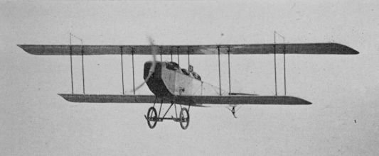
Curtiss JN, prototype Jenny.
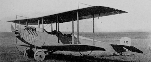
Curtiss JN-2 serial 42.
The Army's remaining JN-2s were all fitted with JN-3 wings of unequal span having ailerons on the upper surfaces only.
The Army's remaining JN-2s were all fitted with JN-3 wings of unequal span having ailerons on the upper surfaces only.
CURTISS N SERIES
The Curtiss N was a contemporary of the British-designed J and differed from it mainly in airfoil section and the location of the ailerons between the wings in the manner of earlier Curtiss models. The single model N (serial 35) procured by the Army in 1914 was tested both with straight wings and the high degree of dihedral illustrated.
The single Curtiss Model O was identical except for being a side-by-side two seater. The later N-8, four of which were used on the Mexican border in 1916 (serials 60-63) was virtually indistinguishable from the JN-3.
Fourteen Army N-9s of 1917 (serials 429-442) were standard Navy trainers, single-float versions of the Army JN-4A fitted with longer span three-bay wings. Filled-in areas on the upper wing kingposts were “skid plates”. Span, 53 ft. 4 in.; length, 32 ft. 7?in.; wing area, 488 sq. ft.; empty weight, 1,860 lb.; gross weight, 2,390 lb.; high speed, 65 m.p.h.

Curtiss N with extra dihedral
CURTISS R SERIES
The Curtiss Rs were designed as 2-seat heavy-duty workhorses in 1915, and were initially powered with the 150 h.p. Curtiss VX engine. The Army bought 12 R-2s (serials 64/75) in 1916, followed by 53 improved R-4s (including 177/187 and 281/316) with 200 h.p. Curtiss V-2 engines. The R-4s were used on the Mexican border and later as bomber trainers. In 1918, some were converted to Liberty-powered mailplanes for the Post Office under the designation of R-4LM (inc. 39369). E
<...>
Data for R-4: Span, 48 ft. 4 1/4 in.; length, 28 ft. 1 3/4 in.; wing area, 545 sq. ft.; empty weight, 2,225 lb.; gross weight, 3,272 lb.; high speed, 90 m.p.h.
The Curtiss Jennies
The word “Jenny” (or “Jennie”) is one of those entirely unofficial names applied to a particular aeroplane design that was so suited to the subject that it virtually replaced the regular model designation. The name was a logical derivation of the factory model designation JN, itself the result of combining the best structural features of two earlier models, the J and the N. The slurring of the two separate letters into a single feminine name was inevitable. The remarkable double career of the JN series, one as a World War I trainer and the other as a post-war barnstorming/air-show/private owner type, has made the Jenny one of the most widely known “name” aeroplanes in America. Extensive use of the surplus military model in postwar years gave its name to the entire era to such an extent that there is a tendency today to refer to other contemporary designs as Jennies.
The Jenny originated in England, when Glenn Curtiss hired B. Douglas Thomas, then an engineer at Sopwith, to design a tractor biplane along lines then becoming standardized in England. Thomas completed most of the J design there. The J design was combined with the N early in its career to produce the JN line, but separate development of the N continued to N-9, the last procured by the Army (see page 471) and N-10 for the Navy. The Army evaluated a single JN in 1914 and the first quantity order was for 10 JN-2s with the old Curtiss shoulder-yoke aileron control, in 1915.
Large-scale Jenny procurement began with 94 wheel-control JN-4s in 1916, which were used both as trainers and as observation types on the Mexican Border during General Pershing’s punitive campaign against the bandit Pancho Villa. The JN-4, with ailerons only on the upper wing, was practically identical to the N-8 except for the airfoil section and control system. Curtiss also supplied JN-3s and 4s to England as trainers before the United States entered World War I.
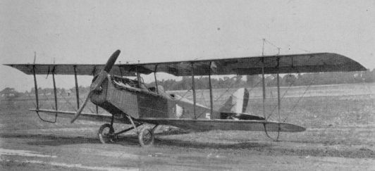
American participation in the War standardized the Curtiss JN-4 series, and the equivalent Standard Aircraft Corporation SJ and J models, as the principal Army primary trainers. Improved Jenny versions with redesigned tails were tested and procured as JN-4A and B but major procurement concentrated on the JN-4D. Powered like its predecessors with the 90 h.p. Curtiss OX-5 engine but featuring stick control instead of the “Dep” wheel control, the JN-4D also had large distinguishing cut-outs in the wings at the fuselage.
Curtiss built 1,412 JN-4A through D and the single JN-4D-2 prototype, while 1,310 Ds were built by six other firms. The JN-4D-2 featured minor refinements and the prototype was outwardly indistinguishable from the Standard D. The 100 production D-2s built by Liberty Iron Works were conspicuous in not having the downward tilt to the engine that was a feature of the JN-4A and D. A Canadian version of the basic JN-4 was built by Canadian Aeroplane Corporation of Toronto, 680 of which were procured by the Army as JN-4Can (for “Canadian”). These were universally referred to as “Canucks” to designate their Canadian origin, and had rounded tail surfaces similar to the original JN-4, stick control, ailerons on both wings, and the engine was installed with the thrust line level.
Curtiss records list only two JN-4Cs built as experimental models with R.A.F. 6 airfoil, but Army records show 276, with different serial numbers from the “Canucks”, on the Air Service inventory in 1919. Several dozen additional “Canucks” with R.C.A.F. serial numbers were absorbed into the U.S. Air Service from Canadian winter flying schools established in Texas.
The next Jenny variant was the JN-4H, an advanced trainer. The “FI” indicated a 150 or 180 h.p. Wright-built Hispano Suiza engine substituted for the OX and did not continue the earlier alphabetical sequence of development. Increased fuel capacity resulted in thickening of the upper wing centre section to accommodate a supplementary fuel tank.
Supplementary designations were applied for specialized use; JN-4HB bomber trainer, JN-4HO observation trainer, and JN-4HG and JN-4HG-2 for one- and two-gun gunnery trainers.
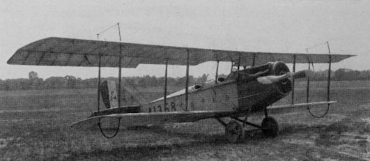
The Army converted one JN-4H (41358) to a prototype bomber trainer under the unofficial designation of JN-5 after installing Curtiss Model R vertical tail surfaces to provide control at the higher gross weight. Curtiss then built 1,035 production versions as JN-6H, the first ones with the R tail but the rest with regular JN-4D/H tails. The special JN-4H designations also applied to JN-6s and were expanded to include the JN-6HP pursuit trainer. Principal JN-6 recognition feature over the JN-4H was the use of ailerons on both upper and lower wings and lower wingtip matching the shape of the upper.
The OX-powered Jennies were declared surplus after World War I and were snapped up by the hundreds by civil owners at prices that dropped as low as $50. The Hispano-powered -4s and -6s remaining in Army service went through various modification programmes and emerged as Model JNS for “JN Standardized”. A few even acquired steel tube fuselages, and the S in the designation was sometimes taken to mean steel. Suffix letters were added to designate the power plant, as JNS-E for those powered with the 180 h.p. Wright-Hispano E. Many were powered with the 150 h.p. Wright-Hispano I, which was misread as the figure One and resulted in the aeroplanes sometimes being called JNS-one’s on those occasions when they were not “Hisso Jennies”. Service modification of the JNs continued as late as 1925, with fiscal serials being assigned. The last Army Jennies, then in use by National Guard Units, were withdrawn from service and scrapped in September, 1927.
TECHNICAL DATA (JENNY)
MANUFACTURER: Curtiss Aeroplane and Motor Co., Inc., Garden City, N.J. TYPE: Trainer.
ACCOMMODATION: Pupil and instructor in tandem open cockpits.
POWER PLANT: (JN-4D) 90 h.p. Curtiss OX-5; (JN-4H, JN-6) 150 h.p. Wright- Hispano A.
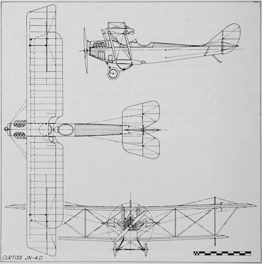
DIMENSIONS: Span, 43 ft. 7f in. Length 27 ft. 4 in. Height 9 ft. 10f in. Wing area 352 sq. ft.
WEIGHTS: Empty (4D) 1,580 lb.; (4H) 1,595 lb.; (6H) 1,797 lb. Gross (4D) 2,130 lb.; (4H) 2,150 lb.; (6H) 2,687 lb.
PERFORMANCE: Max. speed (4D) 75 m.p.h.; (6H) 79-2 m.p.h. Climb, 3,000 ft. in 10 min. Service ceiling (4H) 8,000 ft.; (6H) 5,700 ft. Range, 250 st. miles. ARMAMENT: None.
SERIAL NUMBERS:
JN-4: 79-81; 116-125; 130-136; 230-264; 408-461; 682-699; 731-991.
JN-4A: 1059-1136; 1213-1282.
JN-4C: 1200-1212; 1301-1309.
JN-4CAN: 38536/38586; 39155/39193; 39227/39267; 39314/39352; 39868/39906. JN-4D: 1283-1647; 2405-4075; 4976-5293; 24056-25087; 29105-29210; 33775-34220; 37999-38188; 39868-39869; 39913; 44262-44594; 47340-47576.
JN-4D-2: 47816.
JN-4H: 37933; 38013-38079; 38132-38530; 41358; 41412-41724; 41915-41976; 42047- 42122.
JN-6H: 41725-41914; 41977-42046; 42391; 44153-44246; 44729-44885; 45000-45287; 49117-49122.
The word “Jenny” (or “Jennie”) is one of those entirely unofficial names applied to a particular aeroplane design that was so suited to the subject that it virtually replaced the regular model designation. The name was a logical derivation of the factory model designation JN, itself the result of combining the best structural features of two earlier models, the J and the N. The slurring of the two separate letters into a single feminine name was inevitable. The remarkable double career of the JN series, one as a World War I trainer and the other as a post-war barnstorming/air-show/private owner type, has made the Jenny one of the most widely known “name” aeroplanes in America. Extensive use of the surplus military model in postwar years gave its name to the entire era to such an extent that there is a tendency today to refer to other contemporary designs as Jennies.
The Jenny originated in England, when Glenn Curtiss hired B. Douglas Thomas, then an engineer at Sopwith, to design a tractor biplane along lines then becoming standardized in England. Thomas completed most of the J design there. The J design was combined with the N early in its career to produce the JN line, but separate development of the N continued to N-9, the last procured by the Army (see page 471) and N-10 for the Navy. The Army evaluated a single JN in 1914 and the first quantity order was for 10 JN-2s with the old Curtiss shoulder-yoke aileron control, in 1915.
Large-scale Jenny procurement began with 94 wheel-control JN-4s in 1916, which were used both as trainers and as observation types on the Mexican Border during General Pershing’s punitive campaign against the bandit Pancho Villa. The JN-4, with ailerons only on the upper wing, was practically identical to the N-8 except for the airfoil section and control system. Curtiss also supplied JN-3s and 4s to England as trainers before the United States entered World War I.
American participation in the War standardized the Curtiss JN-4 series, and the equivalent Standard Aircraft Corporation SJ and J models, as the principal Army primary trainers. Improved Jenny versions with redesigned tails were tested and procured as JN-4A and B but major procurement concentrated on the JN-4D. Powered like its predecessors with the 90 h.p. Curtiss OX-5 engine but featuring stick control instead of the “Dep” wheel control, the JN-4D also had large distinguishing cut-outs in the wings at the fuselage.
Curtiss built 1,412 JN-4A through D and the single JN-4D-2 prototype, while 1,310 Ds were built by six other firms. The JN-4D-2 featured minor refinements and the prototype was outwardly indistinguishable from the Standard D. The 100 production D-2s built by Liberty Iron Works were conspicuous in not having the downward tilt to the engine that was a feature of the JN-4A and D. A Canadian version of the basic JN-4 was built by Canadian Aeroplane Corporation of Toronto, 680 of which were procured by the Army as JN-4Can (for “Canadian”). These were universally referred to as “Canucks” to designate their Canadian origin, and had rounded tail surfaces similar to the original JN-4, stick control, ailerons on both wings, and the engine was installed with the thrust line level.
Curtiss records list only two JN-4Cs built as experimental models with R.A.F. 6 airfoil, but Army records show 276, with different serial numbers from the “Canucks”, on the Air Service inventory in 1919. Several dozen additional “Canucks” with R.C.A.F. serial numbers were absorbed into the U.S. Air Service from Canadian winter flying schools established in Texas.
The next Jenny variant was the JN-4H, an advanced trainer. The “FI” indicated a 150 or 180 h.p. Wright-built Hispano Suiza engine substituted for the OX and did not continue the earlier alphabetical sequence of development. Increased fuel capacity resulted in thickening of the upper wing centre section to accommodate a supplementary fuel tank.
Supplementary designations were applied for specialized use; JN-4HB bomber trainer, JN-4HO observation trainer, and JN-4HG and JN-4HG-2 for one- and two-gun gunnery trainers.
The Army converted one JN-4H (41358) to a prototype bomber trainer under the unofficial designation of JN-5 after installing Curtiss Model R vertical tail surfaces to provide control at the higher gross weight. Curtiss then built 1,035 production versions as JN-6H, the first ones with the R tail but the rest with regular JN-4D/H tails. The special JN-4H designations also applied to JN-6s and were expanded to include the JN-6HP pursuit trainer. Principal JN-6 recognition feature over the JN-4H was the use of ailerons on both upper and lower wings and lower wingtip matching the shape of the upper.
The OX-powered Jennies were declared surplus after World War I and were snapped up by the hundreds by civil owners at prices that dropped as low as $50. The Hispano-powered -4s and -6s remaining in Army service went through various modification programmes and emerged as Model JNS for “JN Standardized”. A few even acquired steel tube fuselages, and the S in the designation was sometimes taken to mean steel. Suffix letters were added to designate the power plant, as JNS-E for those powered with the 180 h.p. Wright-Hispano E. Many were powered with the 150 h.p. Wright-Hispano I, which was misread as the figure One and resulted in the aeroplanes sometimes being called JNS-one’s on those occasions when they were not “Hisso Jennies”. Service modification of the JNs continued as late as 1925, with fiscal serials being assigned. The last Army Jennies, then in use by National Guard Units, were withdrawn from service and scrapped in September, 1927.
TECHNICAL DATA (JENNY)
MANUFACTURER: Curtiss Aeroplane and Motor Co., Inc., Garden City, N.J. TYPE: Trainer.
ACCOMMODATION: Pupil and instructor in tandem open cockpits.
POWER PLANT: (JN-4D) 90 h.p. Curtiss OX-5; (JN-4H, JN-6) 150 h.p. Wright- Hispano A.
DIMENSIONS: Span, 43 ft. 7f in. Length 27 ft. 4 in. Height 9 ft. 10f in. Wing area 352 sq. ft.
WEIGHTS: Empty (4D) 1,580 lb.; (4H) 1,595 lb.; (6H) 1,797 lb. Gross (4D) 2,130 lb.; (4H) 2,150 lb.; (6H) 2,687 lb.
PERFORMANCE: Max. speed (4D) 75 m.p.h.; (6H) 79-2 m.p.h. Climb, 3,000 ft. in 10 min. Service ceiling (4H) 8,000 ft.; (6H) 5,700 ft. Range, 250 st. miles. ARMAMENT: None.
SERIAL NUMBERS:
JN-4: 79-81; 116-125; 130-136; 230-264; 408-461; 682-699; 731-991.
JN-4A: 1059-1136; 1213-1282.
JN-4C: 1200-1212; 1301-1309.
JN-4CAN: 38536/38586; 39155/39193; 39227/39267; 39314/39352; 39868/39906. JN-4D: 1283-1647; 2405-4075; 4976-5293; 24056-25087; 29105-29210; 33775-34220; 37999-38188; 39868-39869; 39913; 44262-44594; 47340-47576.
JN-4D-2: 47816.
JN-4H: 37933; 38013-38079; 38132-38530; 41358; 41412-41724; 41915-41976; 42047- 42122.
JN-6H: 41725-41914; 41977-42046; 42391; 44153-44246; 44729-44885; 45000-45287; 49117-49122.

Curtiss JN-4A with high dihedral and bottom-wing ailerons

Curtiss JN-4Can
Curtiss JN-4D
Curtiss JN-4H with Wright-Hispano "A" engine
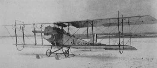
Curtiss JN-6 with skis

This JN-6HG-1 was fitted with a 150 hp Wright-Hispano I engine and used for test work at McCook Field. Here it is seen equipped to launch GL-1 aerial gunnery target glider.
Curtiss JNS-1 converted at Fairfield depot
Curtiss JN-4D
CURTISS TWIN JN
The two-seat Curtiss Twin JN, tentatively designated JN-5, was developed from existing components, with standard JN-4 wings on a wider centre section and JN landing gear. While the prototype used the same dihedral as the JN-4, the other six on the Army order (serials 102-107) had increased dihedral and circular radiators. One twin JN presented to the New Mexico National Guard by the Aero Club of America was taken over by the regular Army (serial 428) and used with the others on the Mexican border in 1916. Span, 52 ft. 9 3/8 in.; length, 29 ft. 4 in.; height, 10 ft. 8 1/2 in.; wing area, 450 sq. ft.; gross weight, 3,150 lb.; high speed 85 m.p.h.
The two-seat Curtiss Twin JN, tentatively designated JN-5, was developed from existing components, with standard JN-4 wings on a wider centre section and JN landing gear. While the prototype used the same dihedral as the JN-4, the other six on the Army order (serials 102-107) had increased dihedral and circular radiators. One twin JN presented to the New Mexico National Guard by the Aero Club of America was taken over by the regular Army (serial 428) and used with the others on the Mexican border in 1916. Span, 52 ft. 9 3/8 in.; length, 29 ft. 4 in.; height, 10 ft. 8 1/2 in.; wing area, 450 sq. ft.; gross weight, 3,150 lb.; high speed 85 m.p.h.

The production Twin JNs differed greatly in detail from the prototype. This was the first for the US Army, Serial No.102.
CURTISS L-2
The four Curtiss L-2s (serials 473/476) of 1917/18 were derived from the 1916 commercial model L triplane, and production of the militarized seaplane version was shared with the Navy. The L-1 was a refinement of the original L, retaining its side-by-side seating but using refined streamlining. The L-2 used a lower wing equal in span to the two uppers and was rigged without dihedral. A few privately-owned Ls and L-1s were donated to the Army or drafted by it along with some commercial flying school JNs after private flying was banned by Presidential Proclamation in 1917.
The four Curtiss L-2s (serials 473/476) of 1917/18 were derived from the 1916 commercial model L triplane, and production of the militarized seaplane version was shared with the Navy. The L-1 was a refinement of the original L, retaining its side-by-side seating but using refined streamlining. The L-2 used a lower wing equal in span to the two uppers and was rigged without dihedral. A few privately-owned Ls and L-1s were donated to the Army or drafted by it along with some commercial flying school JNs after private flying was banned by Presidential Proclamation in 1917.
The L-2 originally had the short lower wing of the Land L-1 but the span was increased to carry the extra weight of the floats.
CURTISS R SERIES
<...>
Eighteen nearly identical R-3s and R-6s (e.g. 505, 508) differed mainly in having 60-foot span 3-bay wings. Some R-6s were delivered as twin-float seaplanes; others converted to Liberty engines became R-6L (e.g. 39956). Some bomber conversions were re-designated R-9 (e.g. 39035/39042, 33748).
<...>
Eighteen nearly identical R-3s and R-6s (e.g. 505, 508) differed mainly in having 60-foot span 3-bay wings. Some R-6s were delivered as twin-float seaplanes; others converted to Liberty engines became R-6L (e.g. 39956). Some bomber conversions were re-designated R-9 (e.g. 39035/39042, 33748).
Curtiss R-6 with three-bay wings
CURTISS S-3
The four Curtiss S-3s (serials 322/325) of 1916/17 were developed from two earlier Curtiss single-seaters that were not bought by the Army. The S-1, known as the Baby Scout, was the smallest aeroplane that could be built around the 90-100 h.p. Curtiss OX-series engine, with a 20-ft. span. The S-2 had a larger upper wing and a unique “wireless” system of wing bracing. The S-3 substituted wire-braced triplane wings but was otherwise identical to the S-2. Although tested with an armament of two forward-firing Lewis guns, the S-3s were unarmed in service and were used only as trainers.
The four Curtiss S-3s (serials 322/325) of 1916/17 were developed from two earlier Curtiss single-seaters that were not bought by the Army. The S-1, known as the Baby Scout, was the smallest aeroplane that could be built around the 90-100 h.p. Curtiss OX-series engine, with a 20-ft. span. The S-2 had a larger upper wing and a unique “wireless” system of wing bracing. The S-3 substituted wire-braced triplane wings but was otherwise identical to the S-2. Although tested with an armament of two forward-firing Lewis guns, the S-3s were unarmed in service and were used only as trainers.

The first Curtiss S-3 seen in August 1917 after the ducted propeller spinner had been discarded.
CURTISS N SERIES
<...>
Fourteen Army N-9s of 1917 (serials 429-442) were standard Navy trainers, single-float versions of the Army JN-4A fitted with longer span three-bay wings. Filled-in areas on the upper wing kingposts were “skid plates”. Span, 53 ft. 4 in.; length, 32 ft. 7?in.; wing area, 488 sq. ft.; empty weight, 1,860 lb.; gross weight, 2,390 lb.; high speed, 65 m.p.h.

Curtiss N-9 in early form
CURTISS 18-B and 18-T
In the spring of 1918, when the only American-designed aircraft in production for the army were trainers, Curtiss developed an entirely new two-seat fighter powered by an equally new all-American engine, the 400-h.p. Kukham K-12. The design was introduced in two forms, the Model 18-B Hornet biplane and the 18-T Wasp triplane. The pilot was provided with two 0-30-in.-calibre Marlin machine guns and the observer/gunner with the standard twin Lewis guns. Two additional Lewises could be mounted to fire downward through the floor. Performance of the 18-T exceeded that of contemporary single-seat fighters, and for a while a stock model with full military load held the world’s speed record at 163 m.p.h. The Armistice ended plans for Model 18 production after one 18-B and one 18-T had been delivered to the Army and several 18-Ts, some with interchangeable two-bay wings under the designation of 18-T-2, had been delivered to the Navy.
Data, 18-B and (in parentheses) 18-T: Span, 37 ft. 5f in. (31 ft. 11 in); length, 23 ft. 4 in. (23 ft. 3 in.); wing area, 337 sq. ft. (309 sq. ft.); gross weight, 3,001 lb. (2,901 lb.); high speed, 160 m.p.h. (163 m.p.h.).

Curtiss 18-T
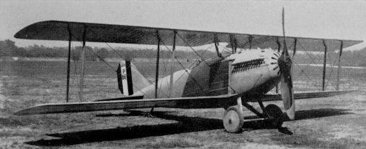
The Curtiss 18B (for biplane) was named Hornet and was identical to the Wasp except for the use of biplane wings.
CURTISS EAGLE
Three examples (64242/64244) of the Curtiss Eagle 10-seat cabin biplane transport were sold to the Army, but differed from the three- engined commercial model in having only a single Liberty engine in the nose. One of the Army Eagles was evaluated as a four-litter ambulance.
Span, 64 ft. 4 1/4 in.; length, 36 ft.; height, 12 ft. 11 in.; wing area, 800 sq. ft.; gross weight, 7,423 lb.; high speed, 100 m.p.h.
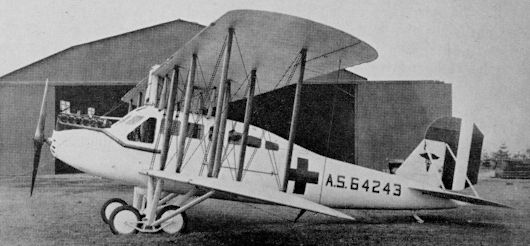
Engineering Division XB-1
The Bristol F.2B Fighter, which served the R.F.C. with distinction from April 1917 until the end of World War I, and thereafter remained in service with the Royal Air Force until 1932, was the subject of extensive but less successful design and production development in the U.S. Its adoption for production in the U.S. followed a recommendation in August 1917 by the Bolling Commission, and a sample F.2B arrived in Washington on September 5. Powered by the standard 200 h.p. Hispano-Suiza engine, it was assigned to the Curtiss Aeroplane and Motor Co., which received contracts for 2,000 examples in October and December.
The Curtiss-built Bristols, officially known as U.S.A. O-1s, had 400 h.p. Liberty 12 engines and changes in construction necessary to accommodate the greater power. The first O-1 flew on March 5, 1918, followed by a further batch of 25 with modifications. Further production was cancelled when the re-engined F.2B proved to be over-powered and unsafe, but Curtiss completed and tested one other example - a second British-built specimen imported without an engine and fitted with the 300 h.p. Hispano-Suiza unit. This same engine was also fitted in the first British sample at McCook Field in April 1918, where it was allocated the project number P-30 and became the prototype U.S. B-1. The other British airframe, project number P-37, later flew with the Liberty 8 engine.
At McCook Field, plans were then made to produce four examples each of the O-1 with ply-covered fuselages and the 300 h.p. Wright Hispano and 290 h.p. Liberty 8 respectively. These were to be known as U.S. B-1 and U.S. B-2, while two more examples with each engine and an entirely new plywood fuselage were to be the U.S. B-3 and U.S. B-4 respectively. The original B-1 and B-2 were dropped, whereupon the B-3 and B-4 became the XB-1 and XB-2; the new XB-2 also was eventually abandoned.
The U.S. XB-1 was damaged before its flight test, and was rebuilt with Browning instead of Marlin guns. Redesignated XB-1A, and numbered P-90, it flew on July 3, 1919. With the war over, only small quantities of the aircraft were procured: a production batch of 40 XB-1As, with 300 h.p. Wright Model H engines, was built in 1920-21 by Dayton-Wright. One of these was tested in 1921 with a 350 h.p. Packard 1 A-1237 engine, and another flew with a Curtiss D-12 engine.
TECHNICAL DATA (XB-1A)
MANUFACTURER: U.S. Army Engineering Division, McCook Field, Dayton, Ohio.
TYPE: Fighter.
ACCOMMODATION: Pilot and gunner.
POWER PLANT: One 300 h.p. Wright H. piston vee in-line.
DIMENSIONS: Span, 39 ft. 4 1/2 in. Length, 25 ft. 6 in. Height, 9 ft. 9 1/2 in. Wing area, 406 sq. ft.
WEIGHTS: Empty, 2,201 lb. Gross, 3,679 lb.
PERFORMANCE: Max. speed, 121-5 m.p.h. at sea level. Cruising speed, 107 m.p.h. at 15,000 ft. Initial climb 8-4 min. to 6,500 ft. Service ceiling, 16,750 ft. Endurance, 3-8 hr. at 10,000 ft.
ARMAMENT: Two fixed forward firing and two flexible 0-30-in. guns.
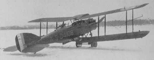
Engineering Division XB-1A
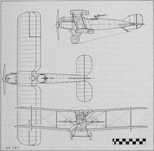
U.S. XB-1
ENGINEERING DIVISION - POMILIO FVL-8 and BVL-12
Among the aeronautical talent sent to the United States by the allies in 1917/18 to help the aviation programme was the Italian designer Ottorino Pomilio, whose firm of Pomilio Brothers in Turin had been notably successful in the manufacture of two-seat observation and bomber models. At the request of the Engineering Division at McCook Field, Pomilio undertook the design of a single seat fighter, the FVL-8, around the new 280-h.p. Liberty 8-cylinder engine and a bomber, the BVL-12, designed around the later 400-h.p. 12-cylinder Liberty.
Both were of conventional all-wood construction, although the plywood fuselages were relatively new to American practice. The outstanding feature of both models was the location of the fuselage above the lower wing instead of on it. The FVL-8 radiator was in the centre section of the lower wing while the BVL-12 used a nose radiator. Six FVL-8s (40081/40086) and five BVL-12s (40087/40091) were built in Indianapolis, Indiana, but were not completed before the Armistice.
Data for the FVL-8 and the BVL-12 (in parentheses) follow: Span, 26 ft. 8 in. (45 ft. 3 in.); length, 21 ft. 8 in. (31 ft. 10 in.); wing area, 284 sq. ft. (621-5 sq. ft.); empty weight, 1,726 lb. (2,824 lb.); gross weight, 2,284 lb. (4,552 lb.); high speed, 133 m.p.h. (Ill m.p.h.).
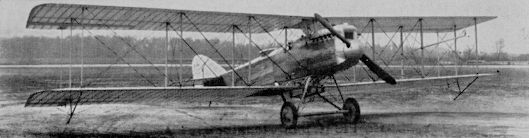
ENGINEERING DIVISION VCP-1/VCP-R/R-1
The VCP-1 was designed in 1918 and built at McCook Field as a fighter, the initials standing for Verville-Clark Pursuit, from the designers’ names. Power for the VCP-1 was the 300-h.p. Wright-Hispano. Two were built (40126, 40127), but only the first was flown. It was modified for the 1920 Pulitzer race - which it won - as VCP-R by installation of a 12-cylinder 660-h.p. Packard 1A-2025 engine and enlarged tail surfaces. The designation was changed to R-1 in 1922.
VCP-1 data: Span, 32 ft.; length, 22 ft. 6\ in.; wing area, 269 sq. ft.; empty weight, 2,014 lb.; gross weight 2,669 lb.; high speed, 154 m.p.h.
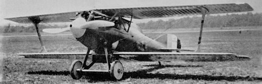
VCP-R
GALLAUDET D-2
Great aerodynamic efficiency was claimed for this aeroplane, with its two 150 h.p. Dusenberg engines buried in the fuselage. Both were connected to a four-blade propeller that was mounted on a ring completely encircling the fuselage aft of the wing. Company advertising claimed a cruising speed of 100 m.p.h. on two engines and 70 m.p.h. on one. While the Army bought only four, similar models were also sold to the Navy, which developed the design further, replacing the twin Dusenbergs with a single Liberty. This improved D-4 model was used as a Naval racer in early post-war years.
Great aerodynamic efficiency was claimed for this aeroplane, with its two 150 h.p. Dusenberg engines buried in the fuselage. Both were connected to a four-blade propeller that was mounted on a ring completely encircling the fuselage aft of the wing. Company advertising claimed a cruising speed of 100 m.p.h. on two engines and 70 m.p.h. on one. While the Army bought only four, similar models were also sold to the Navy, which developed the design further, replacing the twin Dusenbergs with a single Liberty. This improved D-4 model was used as a Naval racer in early post-war years.

GALLAUDET D-2
VICTOR (HEINRICH) ADVANCED TRAINER
Two single-seat “scouts” built in 1917 by the Victor Aircraft Corporation of Freeport, L.I., (539, 540), powered with the 100 h.p. Gnome rotary engine, were also known as Heinrich Pursuits, after the designer, Albert S. Heinrich. They were inadequate by European military standards and were considered only as advanced trainers. Two improved versions (40007, 40008) were built in 1918, powered with the more reliable 80 h.p. Le Rhone rotary and using lighter structure.
Span, 26 ft. 0 in.; wing area, 162-5 sq. ft.; gross weight, 1,235 lb. (Gnome), 1,065 lb. (Le Rhone); high speed, 115 m.p.h. (Gnome), 110 m.p.h. (Le Rhone).
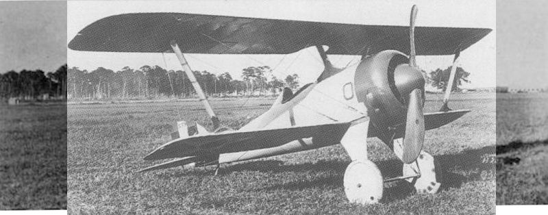
Aerodynamically attractive, the Heinrich Pursuit was tested at McCook Field in 1918.
LOENING M-8
The M-8 design originated in the spring of 1918, when Grover C. Loening was unofficially asked to produce a two-seat fighter superior to the British Bristol F.2B, and initial procurement was expedited by having the Wright-Martin Company request the Loening Aeronautical Engineering Corporation to build two prototypes (40121, 40122) as test beds for the Wright “H” engine, an Americanized version of the 300-h.p. French Hispano-Suiza. The M-8 met all performance expectations, and in spite of certain structural and aerodynamic problems, was slated for a 5,000 machine production order which was cancelled by the Armistice.
Span, 35 ft. 0 in.; length, 25 ft. 0 in.; wing area, 290 sq. ft.; Gross weight, 2,600 lb.; highspeed, 151 m.p.h.
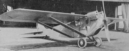
L.W.F. V AND F
The L.W.F. Engineering Co., Inc. (the initials standing for Lowe, Willard and Fowler) was formed in 1915 at College Point, Long Island, and first produced a two-seat observation and training design called Model V. The Army bought 23 variants of this design before World War I (112/113, 447/467) as trainers and for observation, and another 112 in 1917 and 1918 (inc. 705, 2268/2304, 2509/2518, 12883/12894 and 39920/39950). The V-1 had a 140-h.p. Sturtevant engine in place of the 135-h.p. Thomas; the V-2 had a 165-h.p. Hall-Scott and radiator under the upper wing; the V-3 had a 200-h.p. Sturtevant. The Model F was a special V-2 to test the original 8-cylinder Liberty engine, which made its first flight on June 16, 1917.
The L.W.F. Engineering Co., Inc. (the initials standing for Lowe, Willard and Fowler) was formed in 1915 at College Point, Long Island, and first produced a two-seat observation and training design called Model V. The Army bought 23 variants of this design before World War I (112/113, 447/467) as trainers and for observation, and another 112 in 1917 and 1918 (inc. 705, 2268/2304, 2509/2518, 12883/12894 and 39920/39950). The V-1 had a 140-h.p. Sturtevant engine in place of the 135-h.p. Thomas; the V-2 had a 165-h.p. Hall-Scott and radiator under the upper wing; the V-3 had a 200-h.p. Sturtevant. The Model F was a special V-2 to test the original 8-cylinder Liberty engine, which made its first flight on June 16, 1917.

MARTIN MODELS T AND S
The first of an eventual 17 Martin Model T and TT Trainers were sold to the Army in 1914 as the result of a request from Grover Loening, in charge of the Army Aviation School at San Diego, to adapt the current production tractor to dual control as a replacement for the Army’s unairworthy pusher trainers. The initial Ts were procured without engines, the Army installing its own 90 h.p. Curtiss OXs removed from other aeroplanes. A number was shipped to the Philippine Islands for observation duty. A later version of the basic T design featured improved streamlining and a large wing with three bays of struts and used a variety of power plants including Curtiss OX, 125-h.p. Hall-Scott, and 135-h.p. Sturtevant.
<...>
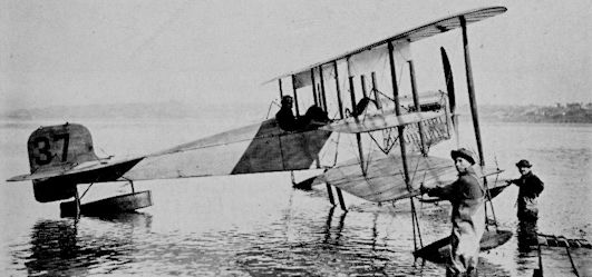
Martin TT Serial 37
MARTIN MODELS T AND S
<...>
The Model S was a direct development of the T, the major changes being the use of the 125-h.p. Hall-Scott A-5 engine and the ailerons built into the upper wing instead of being between the wings. Appearance was distinctive due to the location of the fuselage above the lower wing instead of on it. The Army bought six as observation seaplanes late in 1915 and ordered eight more in June 1916.
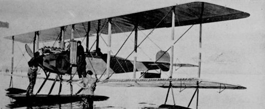
Martin S.
Martin MB-1/T-1
Following his withdrawal from the Wright-Martin combine of 1916, Glenn Martin re-established his own company in Cleveland, Ohio, late in 1917. During conferences held in Washington to unsnarl the World War I aircraft procurement mess, Martin was asked to design a new bomber that would outperform the British Handley-Page. An order for ten MB-1s was signed and the first one flew on August 17, 1918.
Powered with two Liberty engines, the MB-1 (also known as the GMB for Glenn Martin Bomber, to distinguish it from the contemporary J. V. Martin bomber), was more than just a bomber although it followed the established European four-five seat configuration. High power and relatively small size made the MB-1 a multi-purpose design. It was also intended to be a long range observation and photographic machine and its 120 m.p.h. top speed combined with three gun stations gave it escort fighter capability.
The first four MB-1s were built as observation types and the next three were bombers. The eighth was a special long distance version with 1,500-mile range while the ninth was a bomber fitted with a 37-mm. cannon on the nose.
The last aeroplane on the original MB-1 contract was completed in 1919 as a transport by removing the military equipment, raising the top of the fuselage to provide headroom, and adding cabin windows and seats for ten passengers. The open pilot’s cockpit was also converted to a glassed-in enclosure. This version was originally known as GMP for Glenn Martin Passenger, but was redesignated T-1 in the short-lived T-for-Transport series of 1920/23. It was followed by another conversion, the last article in a later four-plane MB-1 contract. Six modified MB-1s were built for the Government Postal Service and two MB-1s were built for the Navy as part of a 10-plane torpedo bomber order.
TECHNICAL DATA (MB-1)
MANUFACTURER: Glenn L. Martin Co., Cleveland, Ohio.
TYPE: Army support reconnaissance and bomber.
ACCOMMODATION: Crew of three.
POWER PLANT: Two 400 h.p. Liberty 12A piston Vee in-line.
DIMENSIONS: Span, 71 ft. 5 in. Length, 44 ft. 10 in. Height, 14 ft. 7 in. Wing area, 1,070 sq. ft.
WEIGHTS: Empty, 6,702 lb. Gross, 10,225 lb.
PERFORMANCE: Max. speed, 105 m.p.h. at sea level. Cruising speed, 92 m.p.h. at sea level. Initial climb, 630 ft./min. Service ceiling, 10,300 ft. Range, 390 st. miles.
ARMAMENT: Five 0-30-in. machine guns in nose and amidships. 1,040-lb. bombs.
SERIAL NUMBERS: 39055/39064; 62948/62951.
Martin MB-2/NBS-1
The MB-2 was a direct development of the MB-1 of 1918, and used essentially the same wooden fuselage and tail unit fitted with larger wings and revised power plant and landing gear installations. The non-staggered wings were hinged at the rear spars just outboard of the engines and folded aft in the manner of the British Handley-Page O-400. Except for later naval designs, the MB-2 was the only large U.S.-designed aeroplane to use this feature. The MB-2 was designed specifically as a night bomber, sacrificing the flashing speed and manoeuvrability of the MB-1, which were not considered essential for a night bomber, to greater bomb load.
Twenty MB-2s were ordered from Martin in 1920, five under the original factory designation (64194/64198) and 15 as NBS-1 (64199/ 64213) in the category for Night Bomber, Short Range under the new Army designating system. Under the prevailing Army policy of dividing the meagre procurements of the time among the hard-pressed manufacturers, additional orders for NBS-1s were placed with other firms. Lowe, Willard, and Fowler (L.W.F.) got an order for 35 (68437/68471) and Curtiss received an order for 50 (68478/68527). Upon completion, the first L.W.F. NBS-1 was sent to Aeromarine as the pilot model for a new 25-plane order (22-201/225) and the remainder were shipped overseas. The last 20 NBS-1s on the Curtiss order were fitted with turbo-superchargers.
The bomb load varied from 1,800 lb. to a maximum of 3,000 lb., with internal stowage in the fuselage for all but the largest bombs. Defensive armament was a pair of 0-30-inch calibre Lewis guns on Scarff rings around the nose and aft cockpits and a single Lewis firing downward from the bottom of the fuselage. Never used in war, the MB-2/NBS-1’s major claim to fame is the sinking of the ex-German battleship Ostfriesland in the controversial Billy Mitchell bombing exercises of July 1921. The NBS-1s, the only production bombers ever specifically designated as night bombers by the U.S. Army, remained in service until replaced by Keystone LB-5s and 6s in 1927/28.
TECHNICAL DATA (NBS-1)
MANUFACTURER: Glenn L. Martin Co., Cleveland, Ohio.
TYPE: Short distance night bomber.
ACCOMMODATION: Crew of four.
POWER PLANT: Two 420 h.p. Liberty 12 piston Vee in-line.
DIMENSIONS: Span, 74 ft. 2 in. Length, 42 ft. 8 in. Height, 14 ft. 8 in. Wing area, 1,121 sq. ft.
WEIGHTS: Empty, 7,269 lb. Gross, 12,064 lb.
PERFORMANCE: Max. speed, 99 m.p.h. at sea level. Cruising speed, 91 m.p.h. Initial climb, 391 ft./min. Service ceiling, 8,500 ft. Range, 558 st. miles.
ARMAMENT: Five 0-30-in. guns in nose and amidships.
SERIAL NUMBERS:
MB-2: 64194/64198.
NBS-1: 68437/68471 (by LWF); 68478/68527 (by Curtiss); 22-201/225 (by Aeromarine); 64199/64213 (by Martin).
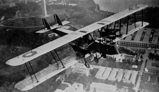
On 17 January 1918 Glenn L Martin received a US Army contract to design and produce ten examples of a twin-engined, four seat reconnaissance bomber. In the absence of any military lead, the aircraft was called the GMB, short for Glenn Martin Bomber and came together fairly quickly under the supervision of Martin's Young Chief Engineer, Donald W Douglas. First flown on 15 August 1918, the GMB was powered by two 400hp Liberty 12As that gave the biplane atop level speed of 101.5mph at sea level, dropping to 100mph at 6,500 feet. Armed with five .30-inch Marlin machine guns, the GMB could lift a 1.040lb bomb load over a range of 390 miles at a cruising speed of 92mph. With the first aircraft delivered to the US Army in October 1918, the company had delivered all but one by the time of the Armistice, the tenth machine being completed in 1919 as a passenger transport.
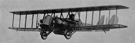
Martin-built NBS-1 with 1,650 lb. bomb
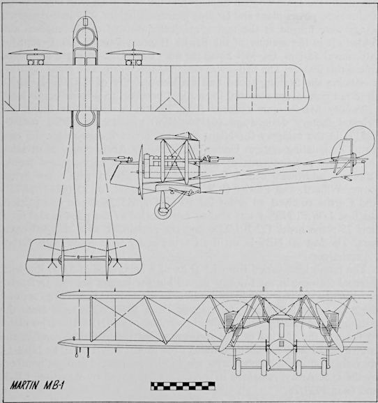
Martin MB-1

Martin MB-2/NBS-1
ORENCO/CURTISS D
The O.E.C. Model D fighter was designed around the 300-h.p. Wright-Hispano engine by the Ordnance Engineering Company of Baldwin, Long Island. Four all-wood prototypes (40107/40110) were built along conventional lines; World War I ended before the first was delivered, but the Army was sufficiently impressed to order 50 production models (63281/63330). Under the prevailing procurement system, the contract was put up for industry-wide bidding and won by Curtiss.
Span, 30 ft.; length, 21 ft. 4 in.; wing area, 242 sq. ft.; empty weight, 1,776 lb.; gross weight, 2,432 lb.; high speed, 147 m.p.h.
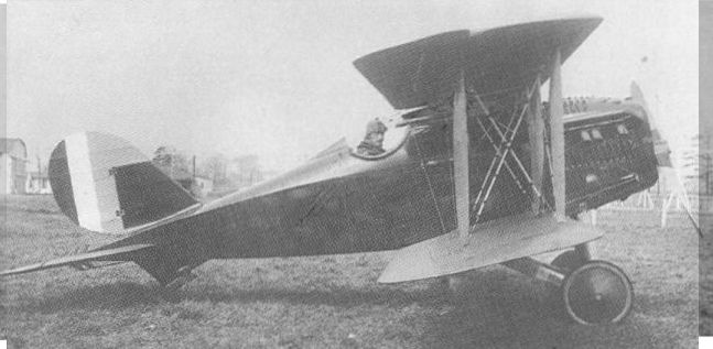
For early post-war service with the Army Air Corps, Curtiss built 50 Orenco Ds after modifying designs of the Ordnance Engineering Corp.
PACKARD-LE PERE LUSAC-11
The Packard-Le Pere LUSAC-11 was designed for the Engineering Division by Captain Le Pere of the French Aviation mission to the U.S. and built by the Packard Motor Car Co. The LUSAC-11 showed heavy French and Italian design influence, with the 400-h.p. Liberty engine carried in a plywood fuselage. Out of 25 production models and two prototypes built, two LUSAC-11s reached France. The LUSAC-21 (40024) was the same airframe with a 16-cylinder 420-h.p. Bugatti engine and the LUSAC-25 (40025) was another variant.
LUSAC-11: Span, 39 ft. 0 1/4 in.; length, 25 ft. 4 5/8 in.; wing area, 415-6 sq. ft.; gross weight, 3,655 lb.; high speed, 136 m.p.h.
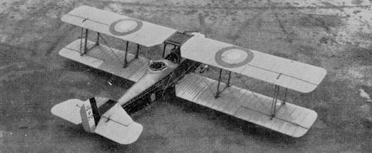
SLOAN/STANDARD H-2 & H-3
The Sloan H-2 of 1916 was a reconnaissance biplane designed by Charles Healey Day, formerly of Martin, and was distinguished by the 10-degree sweepback of the equal-span wings. The Army bought three (76/78), powered with 125 h.p. Hall-Scott A-5 engines.
<...>
The Sloan H-2 of 1916 was a reconnaissance biplane designed by Charles Healey Day, formerly of Martin, and was distinguished by the 10-degree sweepback of the equal-span wings. The Army bought three (76/78), powered with 125 h.p. Hall-Scott A-5 engines.
<...>
SLOAN/STANDARD H-2 & H-3
The Sloan H-2 of 1916 was a reconnaissance biplane designed by Charles Healey Day, formerly of Martin, and was distinguished by the 10-degree sweepback of the equal-span wings. The Army bought three (76/78), powered with 125 h.p. Hall-Scott A-5 engines. Nine improved versions known as H-3 (82/89 and one other) were bought for use on the Mexican border. When the Sloan Aircraft Co., Inc., became the nucleus of the Standard Aero Corporation, the aeroplanes in service became known as Standards. H-3: Span, 40 ft. 1 in.; length, 27 ft.; gross weight, 2,700 lb.; high speed, 84 m.p.h.
The Sloan H-2 of 1916 was a reconnaissance biplane designed by Charles Healey Day, formerly of Martin, and was distinguished by the 10-degree sweepback of the equal-span wings. The Army bought three (76/78), powered with 125 h.p. Hall-Scott A-5 engines. Nine improved versions known as H-3 (82/89 and one other) were bought for use on the Mexican border. When the Sloan Aircraft Co., Inc., became the nucleus of the Standard Aero Corporation, the aeroplanes in service became known as Standards. H-3: Span, 40 ft. 1 in.; length, 27 ft.; gross weight, 2,700 lb.; high speed, 84 m.p.h.
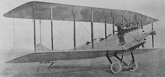
Standard H-3
The Standard J Series
The Standard SJ of 1916 was a direct development of the earlier Sloan biplanes and the Standard H series, all designed by Charles Healey Day. Upon American entry into World War I, the Standard SJ was ordered in quantity as a primary trainer to supplement Curtiss JN-4 production. There was little difference between the two designs, the Standard being recognizable mainly by swept-back wings, somewhat wider gap, and a 4-cylinder Hall-Scott A-7 engine with a narrow vertical radiator mounted on top of the fuselage and ahead of the upper wing. The SJ had a small auxiliary wheel ahead of the main wheels to help prevent noseover in soft ground or bouncy student landings.
While the SJ was entering production, Standard introduced a revised and beefed-up model JR, a two-seater with a 175 h.p. 6-cylinder Hall-Scott A-5 that the company optimistically named the “Pursuit”. This machine was entirely unsuited to European military operations and the Army bought only six as advanced trainers. Certain features of the JR were incorporated into the major production version of the SJ, which became known as the J-1. Principal differences from the previous models were deletion of the nose-over wheel and a change from the Deperdussin wheel control system to the more popular stick. The main drawback to the J-1 was the Hall-Scott A-7 engine, which was extremely troublesome and frequently caught fire in the air. Because of this, service use of the Standards diminished as adequate numbers of JN-4s became available. Standard revised the JR-1 in 1918, and produced a new advanced trainer model, the JR-1B, with 150 h.p. Wright-Hispano, nose radiator, equal span wings with lower wing below the fuselage, and new tail surfaces, but the Army bought only six (42111/42116). When the Army started to fly the airmail in May 1918 these were converted to single-seat mailplanes. A further variant was the E-4, identical to the JR-1B except for a longer upper wing.
TECHNICAL DATA (J-1)
MANUFACTURER: Standard Aircraft Corporation, Plainfield, New Jersey.
TYPE: Trainer.
ACCOMMODATION: Pupil and instructor in tandem open cockpit.
POWER PLANT: One 90 h.p. Curtiss OX-5 piston in-line (or 150 h.p. Wright-Hispano A).
DIMENSIONS: Span, 43 ft. 10 in. Length, 26 ft. 7 in. Height, 10 ft. 10 in. Wing area, 429 sq. ft.
WEIGHTS: Empty, 1,557 lb. (1,660 lb.). Gross, 2,070 lb. (2,206 lb.). PERFORMANCE: Max. speed, 69-5 m.p.h. (85 m.p.h.). Initial climb, 70 ft./min. (590 ft./min.). Service ceiling, 5,800 ft. (15,000 ft.).
ARMAMENT: None.
KNOWN SERIAL NUMBERS:
SJ, J-1: 193/208; 960-1056; 1660/2403; 4477/4994; 22403/22803; 41208/41357.
JR-1B: 42111/42116.
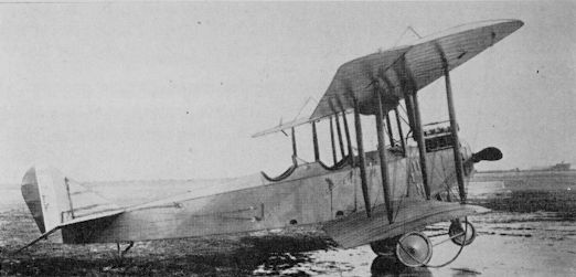
Standard SJ-1

Standard J-1
STANDARD E-1/M-DEFENSE
Two prototypes (33769/33770) of the Standard E-1, a 1917 design, were tested as fighters but production orders were placed for 460 E-1 as advanced trainers. Thirty-three (44542-44574) were delivered with Gnome 100 h.p. rotary engines, followed by 60 designated M-Defense (44575/45577, 49156/49212) and 75 identical E-1s (49133/49207) with the 80 h.p. Le Rhone. After the war, Sperry converted three E-1s, which were given new serial numbers (64228/64230), to radio-controlled aerial torpedoes by lengthening the fuselage and making other essential modifications. This conversion was part of a contract for the similar conversion of several Sperry M-1 Messengers (page 506) and the resulting Sperry MAT designation was also attached to these aeroplanes.
Two prototypes (33769/33770) of the Standard E-1, a 1917 design, were tested as fighters but production orders were placed for 460 E-1 as advanced trainers. Thirty-three (44542-44574) were delivered with Gnome 100 h.p. rotary engines, followed by 60 designated M-Defense (44575/45577, 49156/49212) and 75 identical E-1s (49133/49207) with the 80 h.p. Le Rhone. After the war, Sperry converted three E-1s, which were given new serial numbers (64228/64230), to radio-controlled aerial torpedoes by lengthening the fuselage and making other essential modifications. This conversion was part of a contract for the similar conversion of several Sperry M-1 Messengers (page 506) and the resulting Sperry MAT designation was also attached to these aeroplanes.
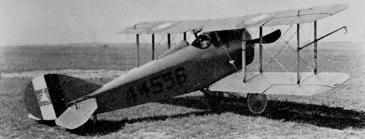
Standard E-1
STURTEVANT S AND S-4
In 1915, Grover Loening left the employ of the Army at San Diego and joined the Sturtevant Aeroplane Co. of Boston, Mass., as chief engineer. He developed a series of trainers and observation types for both the Army and Navy. Seven Model S advanced trainers (inc. 110 and 111) were sold to the Army, and four S-4 “Battleplanes” (126, 127, 214 and 215) were disarmed and converted to conventional observation types for use on the Mexican border in 1916. Model S: 150 h.p. Sturtevant; span, 48 ft. 8 in.; length, 29 ft. 0 in.; gross weight, 3,100 lb.; high speed, 75 m.p.h.
In 1915, Grover Loening left the employ of the Army at San Diego and joined the Sturtevant Aeroplane Co. of Boston, Mass., as chief engineer. He developed a series of trainers and observation types for both the Army and Navy. Seven Model S advanced trainers (inc. 110 and 111) were sold to the Army, and four S-4 “Battleplanes” (126, 127, 214 and 215) were disarmed and converted to conventional observation types for use on the Mexican border in 1916. Model S: 150 h.p. Sturtevant; span, 48 ft. 8 in.; length, 29 ft. 0 in.; gross weight, 3,100 lb.; high speed, 75 m.p.h.

Sturtevant Model S
THOMAS D-5
The two-seat Thomas D-5 observation design, powered by a 135-h.p. Thomas engine, was designed for the Thomas Brothers Aeroplane Company of Bath, N.Y., by B. Douglas Thomas, (no relation) who had designed the Model J for Curtiss while still in England after leaving the employ of Avro. His first Thomas Bros, design, the T-2, was an attempt to improve on the Curtiss J. Work was started at Bath in 1914, but was completed following a move to Ithaca, N.Y. The British Thomas became chief designer for Thomas Brothers, and retained the position after the aeroplane and engine manufacturer merged with the Morse Chain Company of Ithaca. Two D-5s (serials 114/115) were bought by the Army for evaluation. Span, 52 ft. 9 in.; length, 29 ft. 9 in.; empty weight, 1,300 lb.; gross weight, 2,500 lb.; high speed, 86 m.p.h.
The two-seat Thomas D-5 observation design, powered by a 135-h.p. Thomas engine, was designed for the Thomas Brothers Aeroplane Company of Bath, N.Y., by B. Douglas Thomas, (no relation) who had designed the Model J for Curtiss while still in England after leaving the employ of Avro. His first Thomas Bros, design, the T-2, was an attempt to improve on the Curtiss J. Work was started at Bath in 1914, but was completed following a move to Ithaca, N.Y. The British Thomas became chief designer for Thomas Brothers, and retained the position after the aeroplane and engine manufacturer merged with the Morse Chain Company of Ithaca. Two D-5s (serials 114/115) were bought by the Army for evaluation. Span, 52 ft. 9 in.; length, 29 ft. 9 in.; empty weight, 1,300 lb.; gross weight, 2,500 lb.; high speed, 86 m.p.h.
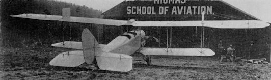
THOMAS D-5
Thomas-Morse S-4 Series
The Thomas S-4, designed by B. Douglas Thomas, was conceived late in 1916 as a Scout to be powered with the 100 h.p. French Gnome rotary engine then being manufactured in the U.S. The single prototype was evaluated by the Army but was rejected as a combat type in favour of more up-to-date European designs. However, the training requirements of the expanding aviation programme of 1917 resulted in production orders from the merged Thomas-Morse Company. The 100 S-4Bs were identical to the prototype except for a considerably shortened fuselage. Structure was all wood with fabric covering. S-4Bs on small twin floats and a tail float were supplied to the Navy as S-5s.
The S-4C was an improved B, the outward differences being straight instead of swept-back trailing edges to the ailerons, and aileron control by push rods and torque tubes in the manner of the French Nieuport 17, an example of which had been sent to the Thomas-Morse Ithaca factory. The first 50 S-4Cs used the 100 h.p. Gnome, but this troublesome power plant was replaced by the 80 h.p. Le Rhone when it became available. Armament was a single 0-30-inch Marlin machine gun or a camera gun. The S-4C contract for 1,050 aircraft was cancelled after the Armistice by which time 497 had been delivered, the final S-4C being numbered 44674.
The large size of the S-4 ailerons resulted in an odd marking situation. Under the initial specifications, the U.S. insignia was to be applied to the wing inboard of the ailerons. This resulted in the top wing markings almost touching at the centre section. Later 1918 applications were moved outward on the aileron.
The last variant, which the Army did not buy, was the speedy taperwinged S-4E. In post-war years this prototype was fitted with a 135 h.p. Aeromarine V-8 engine and used for racing. The S-4s were extremely popular on the surplus market and were widely flown as sport planes until grounded by the increasing stringency of safety regulations in the late 1920s. A few were converted to 3-place Dycer Sport Models by installation of a 90 h.p. Curtiss OX-5 in place of the rotary and the addition of a second 2-seat cockpit. S-4C upper wing panels were also used on the first models of the popular motorcycle-engined Heath “Parasol” lightplane of 1927. S-4Cs saw wide use in Hollywood war films of the 1930s, and a number have been restored by the antique aeroplane fans in the years since World War II.
TECHNICAL DATA (S-4C)
MANUFACTURER: Thomas-Morse Aircraft Corp., Ithaca, New York.
TYPE: Advanced trainer.
ACCOMMODATION: Pilot only.
POWER PLANT: 80-h.p. Le Rhone piston radial.
DIMENSIONS: Span, 26 ft. 6 in. Length, 19 ft. 10 in. Height, 8 ft. 1 in. Wing area, 145 sq. ft.
WEIGHT: Gross, 1,330lb.
PERFORMANCE: Max. speed, 97 m.p.h. Initial climb, 10 min. to 7,500 ft.
ARMAMENT: One Marlin 0-30-in. machine gun, or camera gun.
KNOWN SERIAL NUMBERS:
S-4B: 4276/4372 (plus three).
S-4C: 38637/38979; 39882; 41359/41408; 44608/44674. (plus six).
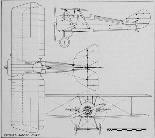
Thomas-Morse S-4C
Thomas-Morse and Boeing MB-3/R-Series
When the problem of producing new aircraft of American design instead of building current European types was handed to the U.S. aircraft industry in the spring of 1918, Thomas-Morse was asked to develop a single-seat fighter superior to the French Spad. Four MB-3 prototypes were ordered. Power plant was the new 300 h.p. Wright “H”, American production version of the French Hispano-Suiza, and the general appearance of the MB-3 showed heavy Spad influence. The first prototype did not fly until the spring of 1919, but even with the War over the Army was sufficiently impressed to order 50 service models.
A further order for 200 improved MB-3As was won by Boeing in 1920, under the competitive bidding system which then prevailed. The MB-3 As, which retained the old manufacturer’s model number in spite of the new designating system then in effect, differed from the MB-3 mainly in a revised cooling system, with radiators on each side of the fuselage by the cockpit instead of in the upper wing. Armament consisted of one 0-30-inch and one 0-50-inch machine gun or two 0-50s firing through the propeller. Two- and four-blade propellers were used interchangeably on MB-3 As, and some Boeing-built four-bladers were installed on the earlier MB-3.
The MB-3As got off to very inauspicious beginnings at the Boeing plant in Seattle. A Thomas-Morse model provided as a sample had flipped onto its back during a landing at the nearest military airfield, so the first of the Boeing-built MB-3As was taken by road to a more suitable field at Camp Lewis, 50 miles south of Seattle. The flight was successful but the Army test pilot did not see a small ditch in a portion of the field. His wheels encountered this during his landing roll and the first MB-3A, too, ended upon its back. Later, Army pilot Tyndall pulled the wings off an MB-3A flown from a short runway near the factory and parachuted to safety after a spectacular low-level bail-out. Boeing made minor structural refinements, and designed and built completely new tail surfaces for the last 50 machines delivered.
The design was constantly plagued by loosening of the structural members as a result of vibration of the heavy engine in its wooden mount, and mechanics complained of poor access to the engine and its accessories. Boeing dissatisfaction with traditional wooden fuselage construction, where the various members were joined through metal fittings, led directly to research that resulted in the arc-welded steel tube fuselage introduced on the Boeing PW-9 and the DH-4M.
One of the first units supplied with the MB-3A was the 94th Pursuit Squadron of World War I fame, then based at Selfridge Field, Michigan. Some MB-3As were also shipped directly from the factory to overseas bases. As MB-3As were replaced in service by newer models, they were relegated to advanced training duties under the designation of MB-3M at Kelly Field, Texas, where they served into 1928.
When the Army became interested in postwar air racing, various manufacturers were asked to produce suitable designs. Thomas-Morse took the simplest course and modified the MB-3 into the MB-6 (68537) by clipping the wings and installing a hotted-up Wright “H” engine of 400 h.p. This plane was re-designated R-2 in the Army Racer series and entered in the 1921 Pulitzer Race. A more extreme racing variant of the MB-3 was the MB-7 (64373) with the same fuselage and power plant but a major change to strut-braced parasol monoplane configuration.
Two R-5 racers were ordered from T-M for the 1922 Pulitzer race. Powered with special 600 h.p. Packard 2A-2025 V-12 engines, these were all metal TM-22 parasol monoplanes developed from a combined primary trainer and pursuit model that B. Douglas Thomas was trying to sell to the Army. The pursuit version, MB-9, was a relatively conventional single-seat all-metal parasol monoplane while the trainer, MB-10, was the same airframe with a new section spliced onto the fuselage to accommodate the second cockpit and a longer nose that placed the 80 h.p. Le Rhone rotary engine farther forward than the fighter’s Curtiss D-12 for balance purposes. The R-5s were notably unsuccessful, as was the trainer-cum-fighter, and the only significant design feature to survive was the wrap-round corrugated metal fuselage construction, which finally won official acceptance on the production O-19 series.
TECHNICAL DATA (MB-3A)
MANUFACTURER: Boeing Airplane Co., Seattle, Washington.
TYPE: Single-seat fighter.
ACCOMMODATION: Pilot in open cockpit.
POWER PLANT: One 300-h.p. Wright H-3 piston Vee in-line.
DIMENSIONS: Span, 26 ft. 0 in. Length, 20 ft. 0 in. Height, 8 ft. 7 in. Wing area, 229 sq. ft.
WEIGHTS: Empty, 1,716 lb. Gross, 2,539 lb.
PERFORMANCE: Max. speed, 141 m.p.h. at sea level. Cruising speed, 125 rn.p.h. Initial climb, 1,235 ft./min. Service ceiling, 19,500 ft. Endurance, 2 1/4 hours.
ARMAMENT: Two fixed forward-firing 0-30-inch guns.
SERIAL NUMBERS:
MB-3: 40092/40095; 63331/63370.
MB-3A: 68237/68436.

Boeing MB-3A in typical 1920 markings
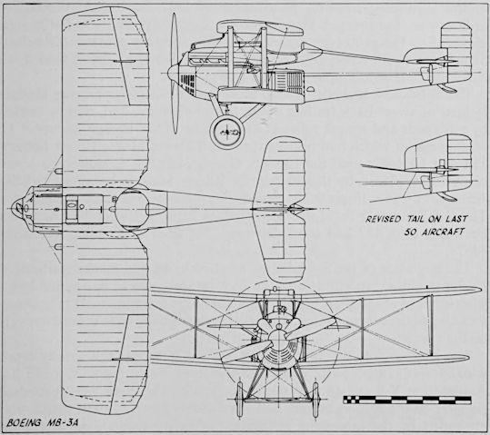
Boeing MB-3A
VOUGHT VE-7, VE-9
The Lewis and Vought VE-7 of 1917 was designed specifically as an advanced trainer, with a 150 h.p. Wright-Hispano “A” engine behind a Spad VII-type radiator. Plans were made for large-scale production, but the demand for advanced trainers was met by converting the Curtiss JN-4 to the Hisso-powered JN-4H, so VE-7 production for the Army was terminated after 14 (inc. 19898/19902) had been delivered by Vought. Two additional improved 180-h.p. models (inc. 40072) were built at McCook Field and four similar models were delivered by Springfield. Two 180-h.p. VE-9 variants (64310, 64316) were procured at the end of the war and an additional 21 (23-379/400) were procured in 1923.
Span, 34 ft. 1 1/2 in.; length, 24 ft. 5 1/2 in.; wing area, 284-5 sq. ft.; empty weight, 1,559 lb.; gross weight, 2,095 lb.; high speed 114 m.p.h.
WRIGHT MODEL A
On February 10, 1908, a contract was signed by the U.S. government for one two-seat Wright Model A at a price of $25,000, with bonus and penalty clauses applying to the performance guarantees. The demonstration took place later in the year, on the Parade Ground at Fort Meyer, Virginia, just outside Washington. By September 17, 1908, all tests had met the requirements. The twin pusher propellers had been changed prior to one of the last flights, on which Lt. Thomas B. Selfridge was to be Orville Wright’s passenger. These were of slightly larger diameter than the originals, and a diagonal wire, normally clear of the adjacent propeller, virbrated excessively in a certain airspeed range and fouled it. Selfridge was killed in the resulting crash and Wright was injured. The Model A (Serial 1) was rebuilt and was accepted by the Army the following year. When the Smithsonian Institution requested the world’s first military aeroplane for a display item, the Wright factory restored it as near to the original configuration as was possible. The aeroplane hangs today in one of the main halls of the Smithsonian, almost in sight of the still-extant original flying site.
Span 36 ft. 4 in.; length, 28 ft.; empty weight, 740 lb.; gross weight, 1,200 lb.; high speed, 44 m.p.h.

WRIGHT MODELS B AND C
The Model B was a greatly improved A, the major change being relocation of the elevators from a position ahead of the wings to a rearward position in contemporary “Tractor” configuration. The wing-warping, two-lever controls, and chain-driven propellers behind the wings were retained but wheel landing gear replaced the skids of the original A, which was launched down a rail by a falling weight. The two Bs (serials 3 and 4) were used as trainers, with instructor and student sharing some of the controls, which were not completely duplicated. The seven Model Cs (serials 7, 8, 10-14), practically identical to the B, eliminated this by installing full dual controls. On some, the lever controls were replaced with two wheels mounted on a single yoke.
Span, 38 ft.; length, 30 ft.; empty weight, 930 lb.; gross weight, 1,380 lb.; high speed, 54 m.p.h.

Wright Model B
WRIGHT F AND HS
After the Wright Brothers conformed to the general trend of design by putting the empennage in the rear with their model “B” in 1910, their next step was to abandon open work tail booms in favour of a fuselage that enclosed the two-man crew and the engine. The single Model F produced for the Army by the Wrights (serial 39) retained the old features of warping wing control and chain-drive pusher propellers. An improved Model HS, with shorter wings and a 60 h.p. Wright replacing the 90 h.p. Austro-Daimler of the F, was used by the Army at San Diego.
Model F: span 42 ft.; length, 29 ft. 6 in.; gross weight, 2,100 lb.; high speed, 60 m.p.h. Model HS: span, 32 ft.; length, 26 ft 6 in.; wing area, 350 sq. ft.; gross weight, 1,000 lb.; high speed, 70 m.p.h.
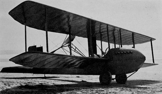
Wright Model HS
WRIGHT-MARTIN R
In September 1916 the Glenn L. Martin Company and the various Wright interests combined with the Simplex Automobile Company and the General Aeronautical Corporation to form the Wright-Martin Company. Martin retained the Los Angeles factory to complete earlier Army contracts, including two 125 h.p. Hall-Scott powered Model Rs (108, 109) with one-piece round rudders, under his own name. The following 12 Rs (522/533) powered by the 150 h.p. A-5A and with fixed vertical fin, including the last three on pontoons, were delivered as Wright-Martin.
In September 1916 the Glenn L. Martin Company and the various Wright interests combined with the Simplex Automobile Company and the General Aeronautical Corporation to form the Wright-Martin Company. Martin retained the Los Angeles factory to complete earlier Army contracts, including two 125 h.p. Hall-Scott powered Model Rs (108, 109) with one-piece round rudders, under his own name. The following 12 Rs (522/533) powered by the 150 h.p. A-5A and with fixed vertical fin, including the last three on pontoons, were delivered as Wright-Martin.
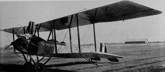
BREGUET 14
Two versions of the 1917 French Breguet 14 combined with the French Salmson 2A-2 to form the main two-seater strength of the A.E.F. until the “Liberty Planes” went into action in August 1918. The Breguet 14A-2 was a “Corps d’Armee”, an observation type, while the 14B-2 was a day bomber. The two were easily distinguishable by the longer lower wing on the B, which was also fitted with a spring-loaded full-span automatic flap that acted as a camber-changing device. Unorthodox by prevailing French standards was the bolted aluminium tube fuselage construction, but the negatively-staggered wings, generally considered unorthodox, were fairly common to several French designs. Two different power plants were used, the 6-cylinder Italian Fiat of 285 h.p. and the 300-h.p. French Renault V-12. A few Breguets sent to McCook Field for test were fitted with Liberty engines.
Data for Breguet 14A (Liberty engine): Span, 47 ft. 3 in.; length, 29 ft. 2 in.; wing area, 527 sq. ft.; empty weight, 2,392 lb.; gross weight 3,771 lb.; high speed, 129 m.p.h.
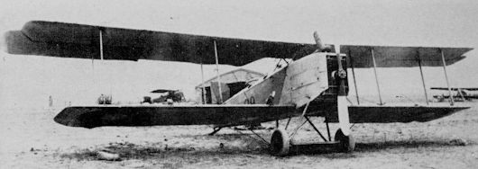
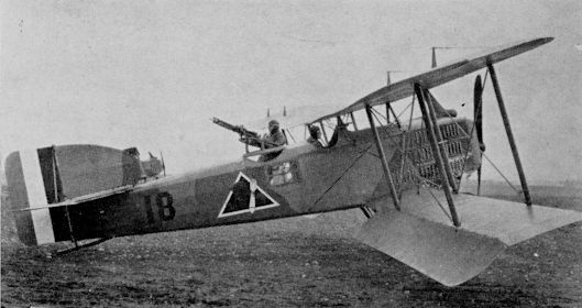
CAUDRON G-IIIE-2 AND G-IVA-2
Two separate but related French Caudron models were used by the A.E.F. as trainers. The G-IIIA-2, originally an observation, or “Corps d’Armee” type of 1914/15, was a single-engined two seater used in 1918 as a primary trainer. The pilot and student sat in tandem in a “bath tub” nacelle behind an 80-h.p. Le Rhone 9-cylinder rotary engine or a 90-h.p. 10-cylinder twin-row Anzani radial. The tail surfaces were supported by tail booms in the manner of contemporary pusher types, but in the Caudron designs the lower booms formed part of the main landing gear and also served as the tailskids. The airfoil was single-surface aft of the rear spar, and late versions of the 192 A.E.F. G-IIIE-2s (“E” indicated “Ecole”, sometimes “Entrainment”, or trainer, in French nomenclature) used ailerons in the upper wing in place of the original wing warping.
<...>
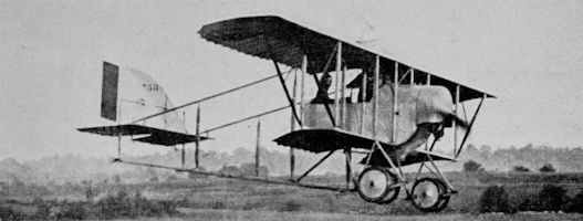
CAUDRON G-IIIE-2 AND G-IVA-2
<...>
The 10 Caudron G-IVs procured by the A.E.F. had been built as “Corps d’Armee” types and retained their original G-IVA-2 designations while serving as American trainers. In design concept the G-IV, the first twin-engine military airplanes to go into action in World War I, was merely a G-III expanded to a twin-engine type using the same Le Rhone engines. As with the majority of obsolete aircraft obtained from the French, the Caudrons were delivered with French markings. The American colour arrangement was painted over the French on some, while others were flown as received.
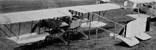
DORAND A.R.1 & A.R.2
The Dorand A.R.1 and 2, with nose and wing radiators for 200 and 190 h.p. Renault engines, respectively, were direct 1917 developments of a pre-war design by Colonel Dorand of the Section Technique d’Aviation of the French Army and were built in French Government shops at Chalais-Meudon. Unconventional features of the design were negatively-staggered wings and a lower wing set well below the fuselage. The A.E.F. bought 22 A.R.1s and 120 A.R.2s, and used them as trainers rather than combat observation types.
A.R.1: Span, 43 ft. 7 in.; length, 30 ft.; wing area, 540 sq. ft.; gross weight, 2,900 lb.; high speed, 92 m.p.h.
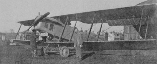
FARMAN F-40
The 30 examples of the F-40 used in the A.E.F. were trainers flown under their original designations of F-40A-2 and F-40P-2 (“P” for Photographic). The Model 40 was a cleaned-up version of the classic Farman “Boxkite” pusher of pre-war and early World War I years. The nacelle of the F-40 was of laminated wood veneer instead of the earlier framework boxes and almost completely enclosed the 130-h.p. Renault V-12 engine. No A.E.F. Farmans were flown in the U.S. after World War l but a number of French surplus models, the slightly improved 46E-2, were dumped on the American market.
The 30 examples of the F-40 used in the A.E.F. were trainers flown under their original designations of F-40A-2 and F-40P-2 (“P” for Photographic). The Model 40 was a cleaned-up version of the classic Farman “Boxkite” pusher of pre-war and early World War I years. The nacelle of the F-40 was of laminated wood veneer instead of the earlier framework boxes and almost completely enclosed the 130-h.p. Renault V-12 engine. No A.E.F. Farmans were flown in the U.S. after World War l but a number of French surplus models, the slightly improved 46E-2, were dumped on the American market.
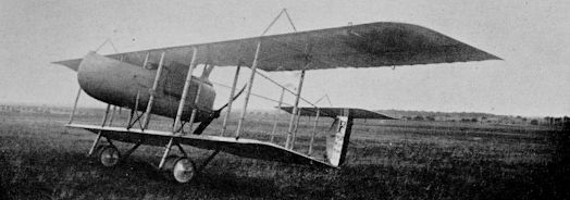
MORANE-SAULNIER MS-12 ROLEUR
While most A.E.F. pilots were trained in the conventional American and British way on dual-control two-seaters, some were started out with a modified form of the French “grass-cutting" technique. For this purpose, the Army bought 138 two-seat Morane-Saulnier MS-12s powered with either 50-h.p. Gnome rotary engines or Anzani radials. MS-12s were used for dual instruction and differed from the Baby Bleriots used by the French in being fitted with ailerons.
While most A.E.F. pilots were trained in the conventional American and British way on dual-control two-seaters, some were started out with a modified form of the French “grass-cutting" technique. For this purpose, the Army bought 138 two-seat Morane-Saulnier MS-12s powered with either 50-h.p. Gnome rotary engines or Anzani radials. MS-12s were used for dual instruction and differed from the Baby Bleriots used by the French in being fitted with ailerons.

Morane 12R2
MORANE-SAULNIER 30 E1
The unique strut-braced Morane MS-30 was typical of much of the second-line and sub-standard combat equipment procured from the French government that was used for training the A.E.F. While earlier versions with the 160-h.p. Gnome rotary engine had been developed as fighters, the one-gun MS-27 and the two-gun MS-29, the type proved unsuited to combat and the lower-powered MS-30 was built strictly as an advanced trainer as shown by the E-for-Entrainment designation. Power was the 120 h.p. Le Rhone. Fifty-one were procured for the A.E.F.
Span, 28 ft. 7 in.; length, 18 ft. 8 in.; gross weight, 1,155 lb.; high speed, 120 m.p.h.

Morane 30E1
NIEUPORT 2-SEAT TRAINERS
The Nieuport Model 10 was one of the first armed tractor two-seaters, with the gunner in the front cockpit standing up with his shoulders through a hole in the upper wing in the pre-synchronized gun days of 1914/15. The famous single-seat Model 11 “Bebe” followed and the Model 12 was a typical armed two-seater of 1915/16, with the gunner in the rear cockpit. Three trainers derived from the Model 12 were procured in quantity by the A.E.F.:- 147 model 80E-2 two-cockpit single control, 173 81D-2 two-cockpit dual control (D meant “double command”, or dual control) and 244 83E-2 with semi-dual controls in a single two-seat “Buddy” cockpit. All used the 80-h.p. Le Rhone 9-C engine.
The Nieuport Model 10 was one of the first armed tractor two-seaters, with the gunner in the front cockpit standing up with his shoulders through a hole in the upper wing in the pre-synchronized gun days of 1914/15. The famous single-seat Model 11 “Bebe” followed and the Model 12 was a typical armed two-seater of 1915/16, with the gunner in the rear cockpit. Three trainers derived from the Model 12 were procured in quantity by the A.E.F.:- 147 model 80E-2 two-cockpit single control, 173 81D-2 two-cockpit dual control (D meant “double command”, or dual control) and 244 83E-2 with semi-dual controls in a single two-seat “Buddy” cockpit. All used the 80-h.p. Le Rhone 9-C engine.
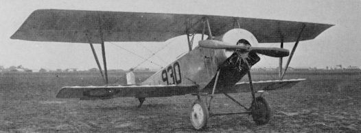
Nieuport 80E-2
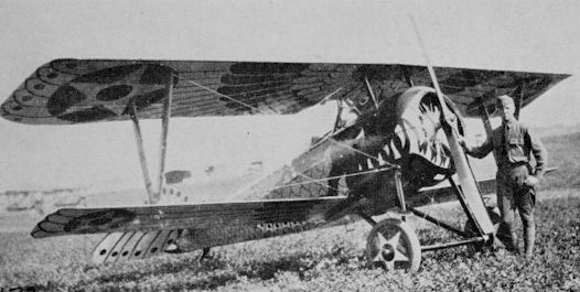
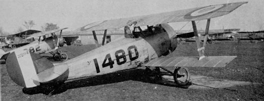
Nieuport 27
NIEUPORT 28C-1
The first fighter to see action with the A.E.F. was the two-gun Nieuport 28, powered by the 160-h.p. Gnome rotary engine. The A.E.F. obtained 298 Model 28s straight from the factory, and 94th and 95th pursuit squadrons were the first to be equipped. The first A.E.F. victories were scored in Nieuports on April 14, 1918, and Douglas Campbell became the first American ace while flying this type. Several Nieuports went to the U.S. after the war.
Span, 26 ft. 3 in.; length, 20 ft. 4 in.; wing area, 215 sq. ft.; empty weight, 1,172 lb.; gross weight, 1,625 lb.; high speed, 122 m.p.h.
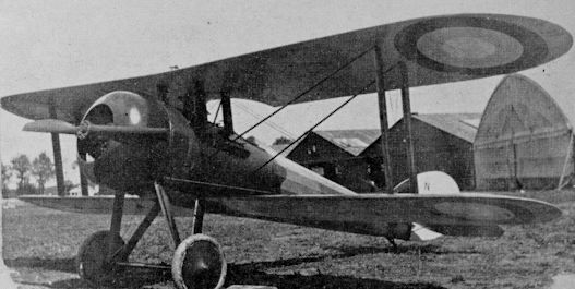
The "demi-diedre" production Nie 28 with 1.5-deg dihedral and deeper cabane.
SALMSON 2A-2
The Salmson 2A-2 was a standard French “heavy” observation design pressed into service with the A.E.F. along with the equivalent Breguet 14 when it became apparent that the American-built “Liberty Planes” would not be available for service when scheduled. Unconventional features of the Salmson were the installation of the 230-270-h.p. Salmson (formerly Canton-Unne) 9-cylinder water-cooled radial engine and the absence of a fixed fin and tailplane. Armament was a single 0-303-in. Vickers and twin Lewis guns. The A.E.F. acquired 705 Salmsons.
The Salmson 2A-2 was a standard French “heavy” observation design pressed into service with the A.E.F. along with the equivalent Breguet 14 when it became apparent that the American-built “Liberty Planes” would not be available for service when scheduled. Unconventional features of the Salmson were the installation of the 230-270-h.p. Salmson (formerly Canton-Unne) 9-cylinder water-cooled radial engine and the absence of a fixed fin and tailplane. Armament was a single 0-303-in. Vickers and twin Lewis guns. The A.E.F. acquired 705 Salmsons.
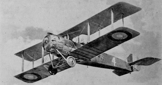
SPAD VII
The Spad VII, (with the model number appearing both in Roman and Arabic figures) was one of the most famous French fighters of World War I. The letters formed the abbreviation of the name “Societe Pour Aviation et ses Derivees.” It was designed in 1916 around the new 150- h.p. Hispano-Suiza motor and carried a single 0-303-in. Vickers gun in a trough on the nose. The 103rd Pursuit Squadron used Spad VIIs briefly and repainted them with American markings before re-equipping with Spad XIIIs. Some of the other 189 French-built VIIs were procured as fighters, but the majority were used as trainers. Some Spad VIIs built in England by Mann-Egerton remained in service as trainers at Kelly Field, Texas, until 1926.
The Spad VII, (with the model number appearing both in Roman and Arabic figures) was one of the most famous French fighters of World War I. The letters formed the abbreviation of the name “Societe Pour Aviation et ses Derivees.” It was designed in 1916 around the new 150- h.p. Hispano-Suiza motor and carried a single 0-303-in. Vickers gun in a trough on the nose. The 103rd Pursuit Squadron used Spad VIIs briefly and repainted them with American markings before re-equipping with Spad XIIIs. Some of the other 189 French-built VIIs were procured as fighters, but the majority were used as trainers. Some Spad VIIs built in England by Mann-Egerton remained in service as trainers at Kelly Field, Texas, until 1926.
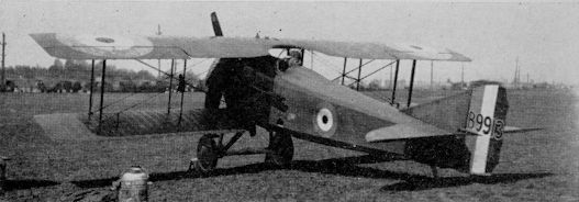
SPAD 11A-2 and 16 A-2
The Spad 11 and 16 were fast two-seat reconnaissance types developed from the Spad VII. Retaining the same short nose of the single seater made it necessary to sweep back the wings of the two seater for balance purposes. Thirty-five 11A-2s were procured, and have erroneously been referred to ever since as Spad 112 because the caption on the most-used photo released by the Office of Public Information in World War I inadvertently left the letter A and the dash out of the designation 11 A-2. The Model 16, of which there were six in the A.E.F. was an identical airframe with a 250-h.p. direct drive Lorraine engine.
The Spad 11 and 16 were fast two-seat reconnaissance types developed from the Spad VII. Retaining the same short nose of the single seater made it necessary to sweep back the wings of the two seater for balance purposes. Thirty-five 11A-2s were procured, and have erroneously been referred to ever since as Spad 112 because the caption on the most-used photo released by the Office of Public Information in World War I inadvertently left the letter A and the dash out of the designation 11 A-2. The Model 16, of which there were six in the A.E.F. was an identical airframe with a 250-h.p. direct drive Lorraine engine.
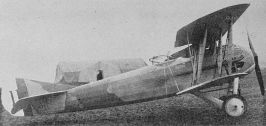
SPAD XIII
The Spad XIII C-1 was a direct development of the single-gun 150 h.p. Spad VII of 1916, and was one of the European designs selected by the famous Bolling Commission for mass production in the United States. Orders for 2,000 to be built by Curtiss were cancelled and all of the 893 XIIIs delivered to the A.E.F. were procured from the French. A number of XIIIs were fitted with fixed aerial cameras for photo missions.
Principal differences from the Spad VII were the use of the 220-h.p. geared Hispano engine, twin guns, and a general beefing up along with improved streamlining and rounded wingtips.
Significant numbers of XIIIs were shipped to the U.S. after the Armistice and served for a while as first line fighter equipment. They were soon relegated to training duties and the troublesome 220-h.p. Hispano was replaced by an ungeared 180-h.p. Wright-Hispano E. The lower thrust line of the direct-drive engine necessitated a new and revised radiator and nose design. This was the principal recognition feature of the redesignated Spad 13E of 1923 (23-938/948).
Span, 26 ft. 4 in.; length, 20 ft. 4 in.; wing area, 227 sq. ft.; gross weight, 1,811 lb.; high speed, 138 m.p.h.

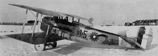
VOISIN 8 AND 10
Even though the basic Voisin design dated back to 1912, the French government tried to sell the U.S. Army later versions as combat types after U.S. entry into World War I. The Model 8 shown was sent to the U.S. for testing in 1917. Ten other examples of the old pusher, with its unique quadricycle landing gear, were purchased in France and used as trainers by the A.E.F., eight Model 8s with 220 h.p. Peugeot engines and two Model 10s with 300 h.p. Renaults.
Even though the basic Voisin design dated back to 1912, the French government tried to sell the U.S. Army later versions as combat types after U.S. entry into World War I. The Model 8 shown was sent to the U.S. for testing in 1917. Ten other examples of the old pusher, with its unique quadricycle landing gear, were purchased in France and used as trainers by the A.E.F., eight Model 8s with 220 h.p. Peugeot engines and two Model 10s with 300 h.p. Renaults.