G.Swanborough, P.Bowers United States Military Aircraft Since 1909 (Putnam)
WRIGHT-MARTIN R
In September 1916 the Glenn L. Martin Company and the various Wright interests combined with the Simplex Automobile Company and the General Aeronautical Corporation to form the Wright-Martin Company. Martin retained the Los Angeles factory to complete earlier Army contracts, including two 125 h.p. Hall-Scott powered Model Rs (108, 109) with one-piece round rudders, under his own name. The following 12 Rs (522/533) powered by the 150 h.p. A-5A and with fixed vertical fin, including the last three on pontoons, were delivered as Wright-Martin.
G.Swanborough, P.Bowers United States Navy Aircraft Since 1911 (Putnam)
WRIGHT-MARTIN R
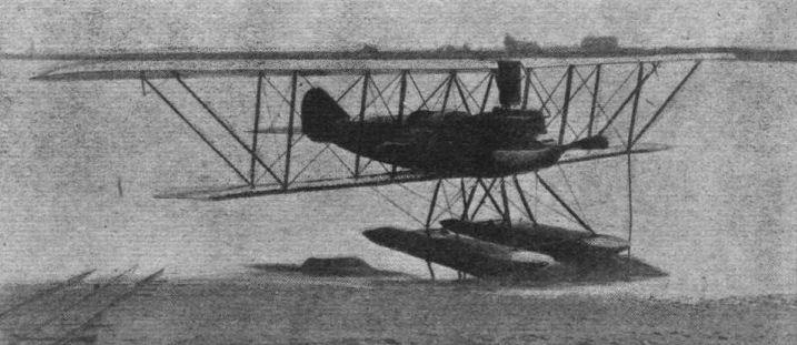
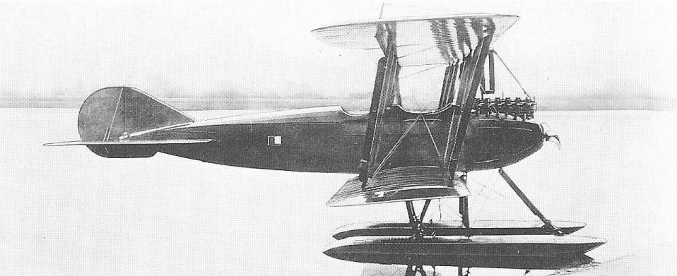
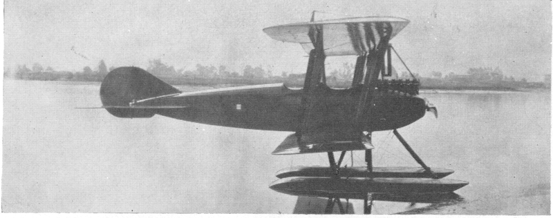
In September 1916 the Glenn L. Martin Company and the Wright interests combined with the Simplex Automobile Company and the General Aeronautical Corporation to form the Wright-Martin Company. Wright was not building aeroplanes at the time, but current Martin designs were delivered as Wright-Martin. Three Model R seaplanes (A288-A290), powered with 150 hp Hall-Scott A-5A engines, were delivered to the Navy in 1917. Span, 50 ft 7 in; length, 27 ft 2 in; gross weight, 2,888 lb; max speed, 86 mph.
Форум Breguet's Aircraft Challenge
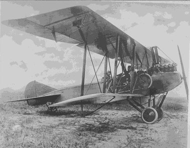
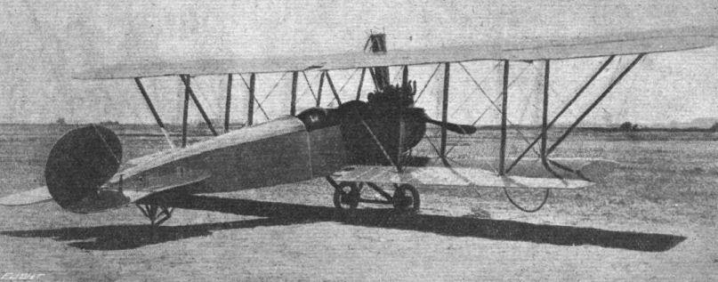
The Martin R or Wright-Martin R reconnaissance biplane of 1916 powered by the ultra heavy Hall-Scott Type A-5. Twenty seven were built for the USA and they were even exported to the Netherlands East Indies, to do their duty in tropical circumstances.
The three Wright-Martin R serials A288-A290 were acquired by the U.S.Navy in 1917. Power was the Hall-Scott A-5A engine of 150 hp.
But the U.S.Navy was not the prime user of this machine, that was the Dutch Navy, who ordered 8 of them in 1916, which arrived on 4 March 1917 in Surabaya (Dutch East Indies - now Indonesia). Floats were quickly left alone and an undercarriage was fitted. I have not checked it exactly, but the machines had difficulty coming out of the water in the tropical atmosphere. Machines at least flew till november 1918.
Two extra machines of the Wright-Martin R were ordered by the Dutch Navy in Holland (MLD - Marine Luchtvaart Dienst).
Ordering machines was possible as US was not at war in 1916
Журнал Flight
Flight, March 1, 1917.
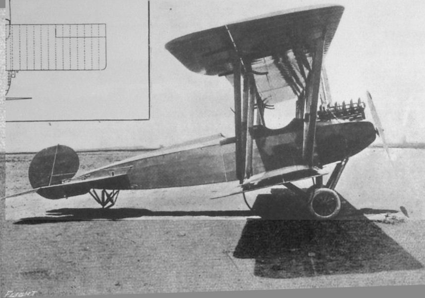
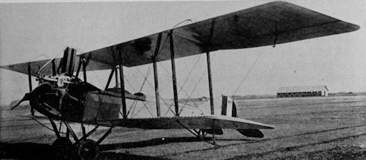
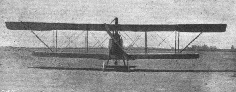
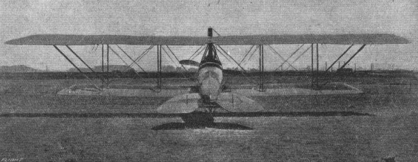
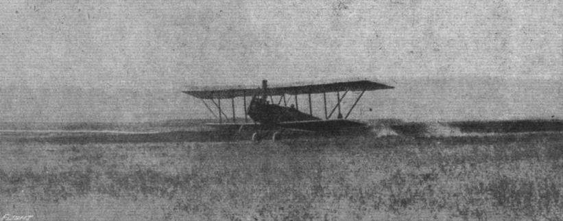
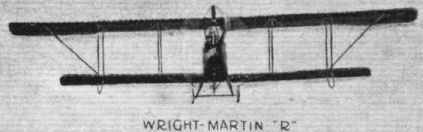
THE WRIGHT-MARTIN MODEL "R" TRACTOR BIPLANE.
THIS machine has been designed for land reconnaissance work in the absence of enemy aeroplanes and for general sport use. From the Wright-Martin Corporation we learn that it gets off the ground at 47 miles an hour and has a high-speed figure of 86 miles, carrying a useful load of 960 lbs., more than half of which may be fuel and oil, sufficient for a non-stop tour of 425 air miles with pilot and observer, and 140 lbs. of luggage. This high speed figure has even been increased to 90 miles an hour in speed tests, and 4,050 ft. have been climbed in 10 minutes.
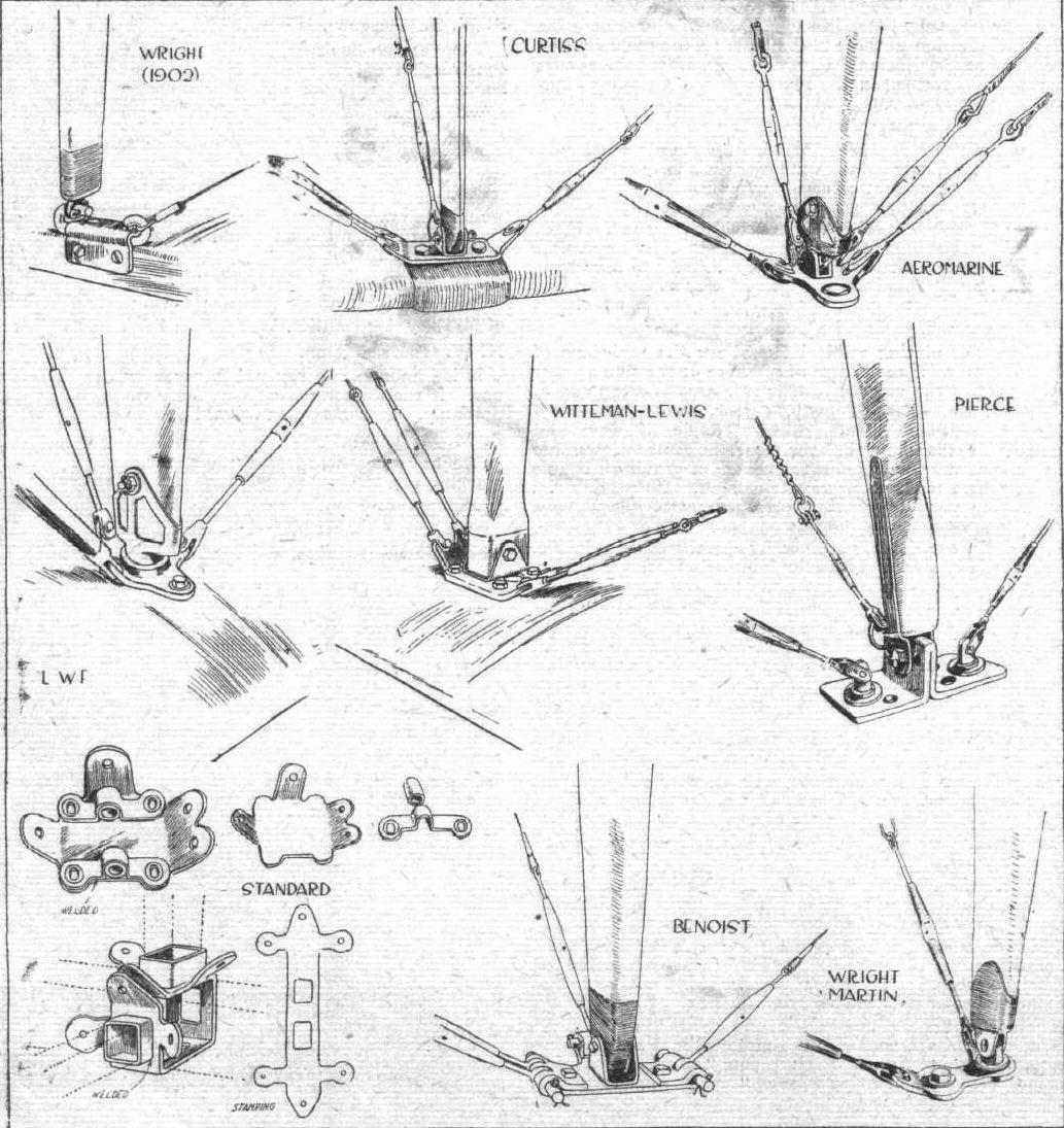
The upper plane, which is of greater span, is in six sections and the lower in four. The sections are secured in assembly by a substantial steel plate and four-bolt system, this same fitting serving as interplane strut anchorage, through the medium of an original universal strut socket, which permits play both fore and aft laterally. R.A.F. 6-section is employed for both top and bottom planes. The wing spars, stringers, leading and trailing edges are of spruce, as well as the end bows, which latter are laminated. The main ribs are of spruce, spaced 15 ins. apart. Between each main rib are two intermediate false ribs, also of spruce. The main ribs are composed of battens and webs bored with the conventional lightening holes. There are vertical reinforcements to strengthen the ribs in longitudinal shear, and the webs are tongued and dove-tail into the rabbitted section of the front and rear lateral spars. The internal bracing is of the conventional system, heavy plated vanadian steel wire being used, with turn-buckles and wiring plates secured to spars by nickel steel bolts. The wing frames are all built up on jig assembly tables, this insuring absolute interchangeability of respective parts and facilitating manufacture and inspection. The wings are covered with Irish linen answering U.S. Signal Corps specifications for strength and quality. The fabric is sewn diagonally and placed "on the bias" over the wing frames with linen tape over the ribs. It is given five coats of Wright-Martin doping mixture and two coats of Rexspar varnish, for weather-proofing. A novel feature is found in the metal strip attached to and protecting the leading edge of the wings. This is applied over the fabric to protect the latter when the machine is dismantled and the wings are set on edge.
The spruce struts are of approved streamline section, hollowed for lightness and offer the greatest possible strength-weight ratio. The respective cross sections are the same throughout the strut length, except at the extreme ends, where the strut tapers to its steel base. They are wrapped at the centre with linen tape, and are quick detachable through the use of vanadian steel pins anchoring the sockets to the main plane fittings. The top plane extensions are supported by means of tubular steel diagonal struts which are fitted with wooden streamliners.
External bracing is by Roebling stranded aviation cable with a novel design of wire terminal end and turnbuckle which presents a minimum of head resistance and weight, and is instantly detachable through the removal of the vanadian steel pins. The wing tips are protected by skids placed below the outermost struts. The complete wing truss is well braced against drift by means of four heavy cables running to the nose of the fuselage. All load and supporting cables are doubled. Both wings are given a moderate dihedral angle laterally (1°), and the upper wing is staggered approximately 12 ins. forward to increase the observer's range of vision.
There is an adjustable horizontal stabiliser, 26,6 sq. ft. in area, on each side of the rear end of the fuselage, to the rear lateral spar of which are hinged the dual elevators. A small vertical fin, 7,3 sq. ft. area, is mounted under the fuselage forward of the rudder. The latter, having an area of 8,7 sq. ft., is hinged to the stern-post of the fuselage and both fin and rudder are braced with heavy sectioned wire and turnbuckles.
Elevator and rudder cables are in duplicate, and enclosed in the fuselage for the greater part of their length. The ailerons, on the upper wings only, are hinged to the outboard sections at the rear wing spar, and are given an increased chord in order to facilitate their action and render the lateral control extremely powerful and positive. They are built up of spruce framing, adequately braced internally to eliminate distortion and have an area of 24 sq. ft. each. A novel method of operating the ailerons has been incorporated which eliminates the necessity of vertical control in either upward or downward direction by direct pull wires led through well-anchored brass tubes running laterally in the lower wings.
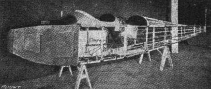
The fuselage has been designed to provide, with the addition of a small fin, the necessary directional stability with a minimum of side resistance. It is of excellent streamline form and tapers from the well-pointed nose to a horizontal knife edge at the rear. Among its features it incorporates the detachable nose which enables the complete motor unit with accessories to be quickly removed and another substituted with a minimum loss of time. This is an especially valuable feature from the military stand-point.
It is of the box girder construction, having ash longitudinal spars throughout, with ash struts and cross members forward and spruce in the rear. It is adequately braced with Roebling vanadian steel wire and turnbuckles. In general design the fuselage is of the conventional two-place tandem type accommodating the motor forward in the detachable nose, the observer or passenger in the front and the pilot in the rear cockpit.
Forward the fuselage is covered in with aluminium side plates and motor hood, as well as deck cowls to the rear of the pilot's seat. The rest of the fuselage is covered with Irish linen of the same specifications as that of the wings, and given the same treatment and finish. The top of the fuselage aft of the rear cockpit is made up as a separate crown unit and is readily detachable in order to facilitate inspection and adjustment of the various components.
On either side of the passenger's seat are the petrol tanks. Fuel is supplied the carburettor through the agency of the air pump attached to the motor. The seats in both cockpits are mounted on tubular steel standards so designed that the seat is braced against both lateral and longitudinal stresses. The dual control is mounted upon a series of triangulated standards, which give adequate rigidity and strength. In order that lost motion will not be experienced in the elevator control, a separate rock shaft coupled with the control standard has been mounted behind the pilot's seat which connects direct with the control arms on the twin elevators and thus eliminates the crossing of control wires. The cockpits are upholstered.
The instrument board is fitted with the usual flight instruments, and the throttle control is mounted on the longeron close to the instrument board. J. M. fire extinguishers are mounted on the fuselage strut directly beneath the dash of the rear cockpit, and is accessible from either cockpit. A motometer, mounted in an accessible place above the engine in the water-cooling system, is readable from both cockpits.
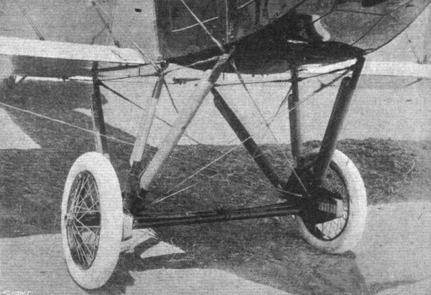
The chassis is of Q.D. tubular steel construction, employing three pairs of struts. The suspension is by means of multiple rubber absorbers coacting with a steel bridge. The axle, of nickel steel tubing, is of the hinged type supported in the centre by 1 1/2-in. tubular steel compression struts, and two adjustable load cables running upwardly to the fuselage. The chassis itself is adequately braced against lateral and longitudinal drift by means of a series of heavy cable tension members. The wheels are of heavy duty type, and fitted with 26 x 4 1/2 in. straight clincher double tube tyres. The wheel hubs are bronze bushed and fitted with an effective lubricating system. The chassis is readily demountable through the removal of the nickel steel assembly bolts.
A tail skid of novel design allows a universal movement of this member to facilitate taxi-ing and minimise wear and tear on the fuselage itself. The skid is supported by a pyramid of four tubular braces attached to the fuselage longerons streamlined with wood fairings. The skid itself is adjustable through a corded rubber shock absorber and aligning cords.
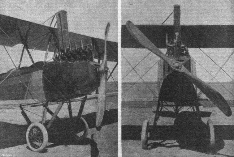
The power plant consists of a six-cylinder 150 h.p. Hall-Scott motor, mounted direct on the shaft of which is an 8 ft. 6 in. tractor screw, having a pitch of 5 ft. 8 in., and an efficiency of 78 to 80 per cent.
The motor is mounted in the detachable nose on pressed steel front and rear plates which support the deep sectioned motor bed. The nose section is well braced with double wire and turnbuckles in the same manner as the fuselage. Birch is used in the construction of the tractor screw, which is built up of inch laminations, with the tips sheathed in copper.
The radiator is of a new type located above the motor and securely braced by stream-lined steel tubes to the upper wings. This new disposition does not appreciably interfere with the vision of either pilot or observer. The control system is optional. It may be either a three-in-one or the standard "Dep." The three-in-one is composed of a vertical column with the wheel for the rudder, lateral movement of the column, for the ailerons and rocking fore-and-aft for the elevators.
The following are the general specifications of this machine :- Overall length, 26 ft. 8 1/2 ins.; overall height, 11 ft. 4 ins.; span (upper), 50 ft. 8 1/2 ins., (lower), 36 ft. 10 3/4 ins.; chord, 5 ft. 6 ins.; gap, 6 ft. ; area, upper 232 sq. ft., lower 178 sq. ft.; total supporting surface, 458 sq. ft. Loading per sq. ft., 6,25 lbs.; loading per b.h.p., 19 lbs.; speed range, 47-86 m.p.h.; climb, 3,500 ft. in 10 mins.; gliding angle, 1 in 8; capacity of petrol tanks, 70 galls.; oil tank, 9,5 galls.; petrol and oil consumption per, hour, 14,2 galls, and 12,5 lbs. respectively. Weight, empty, without power plant, 1,107 lbs.; power plant, 798 lbs.; fuel, &c, for 4 hrs. flight, 480 lbs.; useful load, 503 lbs.; total gross weight, 2,880 lbs.