
Книги
Журнал
Flight за 1914 г.
671
Журнал - Flight за 1914 г.
Flight, January 17, 1914.
INVISIBLE AEROPLANES.
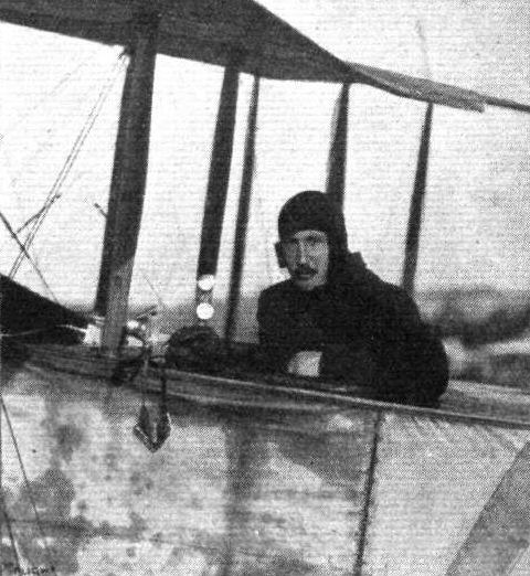
ONE important point which the designer of a military aeroplane has to keep in mind is that his machine, when in the air, must be as hard to discern as possible. There have been several attempts to build an aeroplane with the wings of transparent material, and in May and June of 1912, Lieut. Nittner was flying at Wiener Neustadt, near Vienna, an Etrich monoplane, specially built on such lines for Capt. Petroczy, formerly commandant of the flying corps in the Austrian Army. This machine had the planes covered with a special variety of Emaillite cellulose sheets, and the system has since been developed and patented in all countries by MM. Leduc Heitz, of the Paris House of Emaillite. A photograph is reproduced of the Etrich machine, to which reference has been made, and which those present on the ground were unable to locate in the air when flying at an altitude of between 900 and 1,200 ft. It is stated that at a height of 700 ft. only the framework is dimly visible, and this and the outline of the motor and pilot and passengers present so small an area to rifle or gun fire, that at the rate of speed at which aeroplanes are flown to-day, accurate aiming at such surfaces becomes nearly impossible. There are also secondary advantages in the use of such transparent sheeting in the construction of aeroplanes. For one thing, it enables the pilot to keep an eye upon the interior framework of the planes, and to detect at once any straining or fracture of the ribs, &c. Another advantage is that the highly polished smooth surface reduces the friction, as was proved in the case of Capt. Petroczy's machine, although, as that was the first machine to be so treated, the material used was not so suitable as the latest product. The surface could not be properly tightened, and owing to the sheeting being more or less plastic it presented a wavy surface, while some difficulty was experienced in securely fastening it to the ribs.
As long ago as 1904. Prof. Reisner, of Aachen, suggested that polished celluloid should be utilised for aeroplane sheeting in order to diminish air friction.
Last year, M. W. A. Lebedeff, working in conjunction with the Russian Government, tried to cover a Henry Farman biplane with transparent cellulose sheeting of a somewhat modified composition. This material was not so heavy as that used in Austria, and it was also somewhat stronger (its tensile strength being about 7 kilogs. Per square millimetre of section), but the wavy surface of the wings, due to the flexibility of the material, could not be overcome.
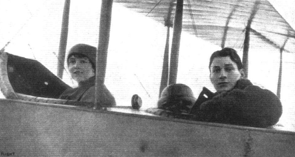
After working at the problem for some time the Emaillite firm have developed a better material which was seen at the Paris Show on the planes of the Moreau monoplane. Instead of using ordinary cellulose sheeting, this machine has what might be termed a reinforced sheeting consisting of two layers of Emaillite with a sheet of silk tulle between them, the tulle being specially treated to render it transparent. That the material is to all intents and purposes transparent is illustrated by the photographs of one of the wings of the Moreau monoplane behind which a man can be clearly seen. The use of the tulle liner not only strengthens the material but it also prevents it sagging or warping between the ribs so that by its use it is quite possible to obtain a smooth and regular surface on the planes. The tensile strength of the material is about nine to ten kilogs. per square millimeter section and a 35 mm. sheeting is sufficient to ensure a tensile strength of about 2,800 to 3,000 kilogs. of the wing covering, a stress which is never attained with the best fabrics in use. The weight of this new Emaillite material does not exceed 375 grammes per square metre, which is but 40 per cent, more than the weight of good doped linen fabric as generally used, so that the increase of weight in the case of ordinary machines would be between 12 and 15 kilogs. It is claimed for this new Emaillite transparent reinforced sheeting that it has all the advantages of that which is not reinforced without its faults. It can be fastened either by nailing, sewing, or by using an adhesive solution. It will not tear or break when anything such as a tool falls upon it, while should it be pierced by a bullet the fabric liner would prevent the damage extending. The British patents for this invention are held by the British Emaillite Co., Ltd., of 30, Regent Street, W. Extensive tests are shortly to be carried out with machines covered in this way, in order to ascertain the height at which they become virtually invisible.
Flight, August 28, 1914.
AIRCRAFT "MADE IN GERMANY"
WHICH MAY BE EMPLOYED AGAINST THE ALLIES.
13. The Etrich Taube,
as the prototype of most German monoplanes, is of particular interest. The wings are of the so-called Zanonia form, having back-swept upturned wing tips, which are flexed up and down for the maintenance of lateral stability. Instead of the usual system of lower bracing cables a biplane type of bracing is secured by means of a boom running out some distance below and parallel with the wings, to which it is connected by short struts diagonally cross-wired. The outer one of these struts is continued upwards above the wing to form a king post, which serves as a support for the cables, keeping the wing tips in their upturned position. The fuselage is of nearly rectangular section, being slightly narrower at the bottom than at the top, and is provided with a turtle back running over its entire length. The flexing elevator forms a continuation of the fixed portion of the tail plane, and the rudder is divided, one half working above and the other below the tail plane. Pilot and passenger sit tandem fashion, the former occupying the rear seat. The chassis bears a slight resemblance to the Bleriot, working on the principle of the deformable triangle, but the shock - absorbing arrangement is different.
The rubber shock absorbers are anchored to the front spar and to a cross piece on the forked chassis strut, so that in heavy landing the spar is likely to suffer, if not breakage, at least weakening through shock. In view of the great amount of head resistance caused by the seemingly unnecessarily complicated wing bracing system employed, it is not surprising that the speed of the machine with a 100 h.p. engine is under 60 m.p.h.
INVISIBLE AEROPLANES.
ONE important point which the designer of a military aeroplane has to keep in mind is that his machine, when in the air, must be as hard to discern as possible. There have been several attempts to build an aeroplane with the wings of transparent material, and in May and June of 1912, Lieut. Nittner was flying at Wiener Neustadt, near Vienna, an Etrich monoplane, specially built on such lines for Capt. Petroczy, formerly commandant of the flying corps in the Austrian Army. This machine had the planes covered with a special variety of Emaillite cellulose sheets, and the system has since been developed and patented in all countries by MM. Leduc Heitz, of the Paris House of Emaillite. A photograph is reproduced of the Etrich machine, to which reference has been made, and which those present on the ground were unable to locate in the air when flying at an altitude of between 900 and 1,200 ft. It is stated that at a height of 700 ft. only the framework is dimly visible, and this and the outline of the motor and pilot and passengers present so small an area to rifle or gun fire, that at the rate of speed at which aeroplanes are flown to-day, accurate aiming at such surfaces becomes nearly impossible. There are also secondary advantages in the use of such transparent sheeting in the construction of aeroplanes. For one thing, it enables the pilot to keep an eye upon the interior framework of the planes, and to detect at once any straining or fracture of the ribs, &c. Another advantage is that the highly polished smooth surface reduces the friction, as was proved in the case of Capt. Petroczy's machine, although, as that was the first machine to be so treated, the material used was not so suitable as the latest product. The surface could not be properly tightened, and owing to the sheeting being more or less plastic it presented a wavy surface, while some difficulty was experienced in securely fastening it to the ribs.
As long ago as 1904. Prof. Reisner, of Aachen, suggested that polished celluloid should be utilised for aeroplane sheeting in order to diminish air friction.
Last year, M. W. A. Lebedeff, working in conjunction with the Russian Government, tried to cover a Henry Farman biplane with transparent cellulose sheeting of a somewhat modified composition. This material was not so heavy as that used in Austria, and it was also somewhat stronger (its tensile strength being about 7 kilogs. Per square millimetre of section), but the wavy surface of the wings, due to the flexibility of the material, could not be overcome.
After working at the problem for some time the Emaillite firm have developed a better material which was seen at the Paris Show on the planes of the Moreau monoplane. Instead of using ordinary cellulose sheeting, this machine has what might be termed a reinforced sheeting consisting of two layers of Emaillite with a sheet of silk tulle between them, the tulle being specially treated to render it transparent. That the material is to all intents and purposes transparent is illustrated by the photographs of one of the wings of the Moreau monoplane behind which a man can be clearly seen. The use of the tulle liner not only strengthens the material but it also prevents it sagging or warping between the ribs so that by its use it is quite possible to obtain a smooth and regular surface on the planes. The tensile strength of the material is about nine to ten kilogs. per square millimeter section and a 35 mm. sheeting is sufficient to ensure a tensile strength of about 2,800 to 3,000 kilogs. of the wing covering, a stress which is never attained with the best fabrics in use. The weight of this new Emaillite material does not exceed 375 grammes per square metre, which is but 40 per cent, more than the weight of good doped linen fabric as generally used, so that the increase of weight in the case of ordinary machines would be between 12 and 15 kilogs. It is claimed for this new Emaillite transparent reinforced sheeting that it has all the advantages of that which is not reinforced without its faults. It can be fastened either by nailing, sewing, or by using an adhesive solution. It will not tear or break when anything such as a tool falls upon it, while should it be pierced by a bullet the fabric liner would prevent the damage extending. The British patents for this invention are held by the British Emaillite Co., Ltd., of 30, Regent Street, W. Extensive tests are shortly to be carried out with machines covered in this way, in order to ascertain the height at which they become virtually invisible.
Flight, August 28, 1914.
AIRCRAFT "MADE IN GERMANY"
WHICH MAY BE EMPLOYED AGAINST THE ALLIES.
13. The Etrich Taube,
as the prototype of most German monoplanes, is of particular interest. The wings are of the so-called Zanonia form, having back-swept upturned wing tips, which are flexed up and down for the maintenance of lateral stability. Instead of the usual system of lower bracing cables a biplane type of bracing is secured by means of a boom running out some distance below and parallel with the wings, to which it is connected by short struts diagonally cross-wired. The outer one of these struts is continued upwards above the wing to form a king post, which serves as a support for the cables, keeping the wing tips in their upturned position. The fuselage is of nearly rectangular section, being slightly narrower at the bottom than at the top, and is provided with a turtle back running over its entire length. The flexing elevator forms a continuation of the fixed portion of the tail plane, and the rudder is divided, one half working above and the other below the tail plane. Pilot and passenger sit tandem fashion, the former occupying the rear seat. The chassis bears a slight resemblance to the Bleriot, working on the principle of the deformable triangle, but the shock - absorbing arrangement is different.
The rubber shock absorbers are anchored to the front spar and to a cross piece on the forked chassis strut, so that in heavy landing the spar is likely to suffer, if not breakage, at least weakening through shock. In view of the great amount of head resistance caused by the seemingly unnecessarily complicated wing bracing system employed, it is not surprising that the speed of the machine with a 100 h.p. engine is under 60 m.p.h.

13. The Etrich Taube.
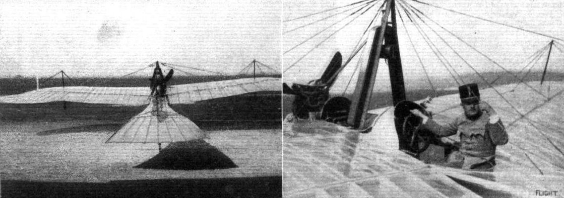
Two views of the Etrich monoplane covered with Emaillite treating and flown by Lieut. Nittner at Wiener Neustadt. It will be noticed especially from the photograph on the right that the inner construction of the planes can be seen through the top surface.
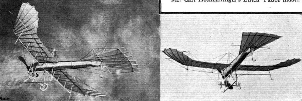
Mr. Carl Hochhaltinger's Etrich Taube model.

13. The Etrich Taube.
Fig. 2. - Sections of tail planes: A, Avro tail, 1910-11. B, Nieuport tail, 1910-11. C, B.E. tail, 1911. D, B.E. tail, 1912.
Fig. 4. Avro biplane, 1910-11.
Flight, July 24, 1914.
SHOREHAM TO HENDON.
SOME IMPRESSIONS OF A NON-STOP FLIGHT.
By MISS M. LOUISE ELLIOTT.
VISITORS to Hendon are accustomed to seeing a little tractor biplane slip out from a group of sheds at the far end of the enclosures, lift and climb steadily in ever-widening circuits, until it becomes an infinitesimal speck which vanishes above the clouds. Suddenly a silver spark flashes out from a space of blue sky, like a new and brilliant evening star - the tractor screw, flashing in the sunlight as the machine turns and commences its descent. It comes back, circles the aerodrome again and again, floating slowly round and downwards with propeller stopped, and, after a perfect landing, finally comes to rest by its own shed.
Possibly the megaphone man has announced the name of the pilot and machine, but if he has not it is of no consequence. "Good wine needs no bush," and Mr. Laurence Hall's flying of the Avro announces itself.
I have done a good deal of passenger flying at Hendon, on different types of aeroplanes, and with some of the best pilots of the day. There is no need to make any odious comparisons, but it may safely be said that the steadiness, controllability, and general comfortableness, if one may put it in that informal way, of the little 50 h.p. Avro make it a delightful machine to fly in, and that anyone who has made even a single flight with Mr. Hall can have nothing but supreme confidence in his ability as a pilot.
Moreover, aerodrome flying is all very well, but the "out and home" variety is better, and a genuine cross-country flight over a fair distance is real aviation, or should be. So altogether, when I found myself, in company with several keenly interested friends, at the very successful inaugural week-end meeting at the Shoreham Aerodrome, and knew that I was to have the privilege of accompanying Mr. Hall on his return flight to Hendon, I felt pleased with myself and all the world.
Shoreham has many of the qualities of the ideal aerodrome - even service, open surroundings, boundaries guiltless of trees, and excellent atmospheric conditions. One of my most delightful recollections will always be a long flight I had with Mr. Hall on the Sunday afternoon. We went out round the country and over the sea, and the sea, beautiful as it always is, never looks so beautiful or so wonderful as from an aeroplane; and my friends told me afterwards that when the machine disappeared through and above the clouds for a time, the excitement among the crowd was intense.
We were to make the return flight on either Monday afternoon or Tuesday morning, according to circumstances, but on Monday the wind was so high that it would have been unwise to start, until too late to reach Hendon by daylight, so Mr. Hall, with sound north-country common sense, utilised the interval in having the machine thoroughly overhauled and tested. One reason for the successful record of the hard-worked little Avro is the fact that it is always kept in the most perfect flying condition, and in this respect it is an object-lesson to many bigger and more ambitious machines. As luck would have it, more things went wrong on that Monday evening than during the preceding six months, but they were all successfully negotiated, from a broken tail-skid to a missing petrol funnel.
Tuesday morning dawned bright and clear, and very soon after the appointed time we were off. We started with two or three typical wide circuits, the Avro climbing, beautifully; but the wind was up early too, and just at first we were badly bumped about - upwards, downwards, first on one side and then the other. The bumps did not worry me in the least, for we steadied again instantly after each one of them, and they really only showed how perfectly the pilot had the machine in hand. I sat and watched the blue sea, veiled by a tender haze towards the horizon, and edged by a white thread of breakers against the stone-coloured beach; the red-and-white toy bungalows grew smaller every moment, and at something over 2,000 ft. the wind grew steady, and we turned and shot inland, still climbing at a terrific pace.
We were very soon well over 4,000 ft., and going across what, to me, was unknown country, with no resemblance to what one sees when travelling to or from Brighton in the ordinary way. Once or twice we saw in the distance a dark patch, which developed into the streets of a town, and fled away behind us. Here and there a dark line marked a railway, a white one a road; a patch of greenish-blue meant water. So we went on through the fresh clear air of the summer morning, high above the dusty, weary world, with everything except ourselves - and when I say "ourselves" I count the Avro as one - unsubstantial as the fabric of a vision. Filmy wreaths of cloud played hide-and-seek with us, or flung their shadows on the dim green fields lying infinitely far below, with the hedges seeming to run into one another as they raced past beneath us. On either side of me our wings stretched out, creamy-golden, the stay-wires flashed in the sunshine like silver; before, the engine sang rejoicingly, and behind, unseen but unfaltering, were the watchful eye and steady hand on which our fates depended.
It was with a positive crash of disappointment that I heard a voice behind me say "Brooklands!" and saw the great motor track, looking like a miniature model, far down beneath us, for, with our low-powered engine, we had expected to take perhaps an hour in getting to Brooklands, and had arranged, therefore, to land there on our way. And now we seemed to have only fairly started, we were going splendidly, and the idea of stopping was most distasteful. To my joy, we did not descend. We had done the greater part of our journey, and had a good half of our resources still in hand. To have turned into the high wind for the sake of making an unnecessary landing would have been sheer waste of time and trouble, and so we left Brooklands behind us and raced ahead.
Just after this, the machine surprised me by wavering a little once or twice, for the first time since we left Shoreham - it had been as steady as a rock ever since. I put it down to the state of the air, which was quite different as we neared the Thames, but Mr. Hall explained afterwards that when we started he had the compass set for Brooklands, and after passing there had been busy resetting it for Hendon, with altered course and wind accordingly. Over the river and beyond it, the wind was very tricky, and there were patches of haze and cloud everywhere; London itself lay under a thick blanket of black smoke. Only a few minutes after crossing the Thames I recognised the Welsh Harp, and then, in no time at all, microscopically tiny and with colours dulled by the mist, the red-white-and-blue pylons of the London Aerodrome.
The song of the engine ceased, the propeller slackened, stopped; and slowly, gently, we floated round the whole extent of the aerodrome for perhaps a couple of circuits. I know of nothing so indescribably fascinating as this particular feat, and Mr. Hall executes it to perfection, but it cannot be done on every machine, nor should it be attempted by any but a thoroughly capable and resourceful aviator, as the sequel shows. Whether the spirits of the air at Hendon were annoyed at having been neglected, even for a week-end, I cannot say, but apparently they withdrew their support from us, for we suddenly and quite simply fell down. I had always wanted to know what this particular experience felt like, and now I do, but I had barely time to realise it properly at the moment. The voice behind me said "Remou!" the nose of the machine went down in a nearly vertical dive, the propeller spun round again, and in far less time than it takes to tell we were on our way in a normal attitude, and at full flying speed. It was a magnificent "save" at the end of an altogether fine piece of flying. I would not have missed it for the world, and my one regret was that there were not more people there to see it.
After that, anything else would have been an anticlimax, so we came down, landing so beautifully that it was impossible to tell when we touched the ground. We made our way to the telephone office, and I addressed the inevitable stack of picture postcards, while Mr. Hall rang up Shoreham to announce our safe arrival. I knew we had done well, but the real fun of the thing only struck me when he got through to his mechanics, who had just settled down to a well deserved breakfast, and found it at first difficult to convince them that we had really reached Hendon. They did not give us credit for getting even so far as Brooklands, and thought we must have come down somewhere en route!
Well, it was not surprising, for we had done the whole journey, from one shed to the other, in forty-five minutes. It may not be a record, but for a little machine like the 50 h.p. Avro, handicapped by carrying a passenger, it was a first-class piece of work. At any rate, I know one person will never forget it - and that is the passenger.
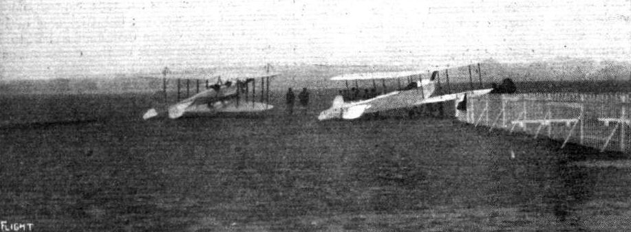
The Handley-Page and Avro biplanes ready to take the air at Hendon.
OFF FOR EASTCHURCH. - Mr. Raynham starting away from Brooklands on Monday to deliver a 50 h.p. Gnome-Avro to the Admiralty at Eastchurch.
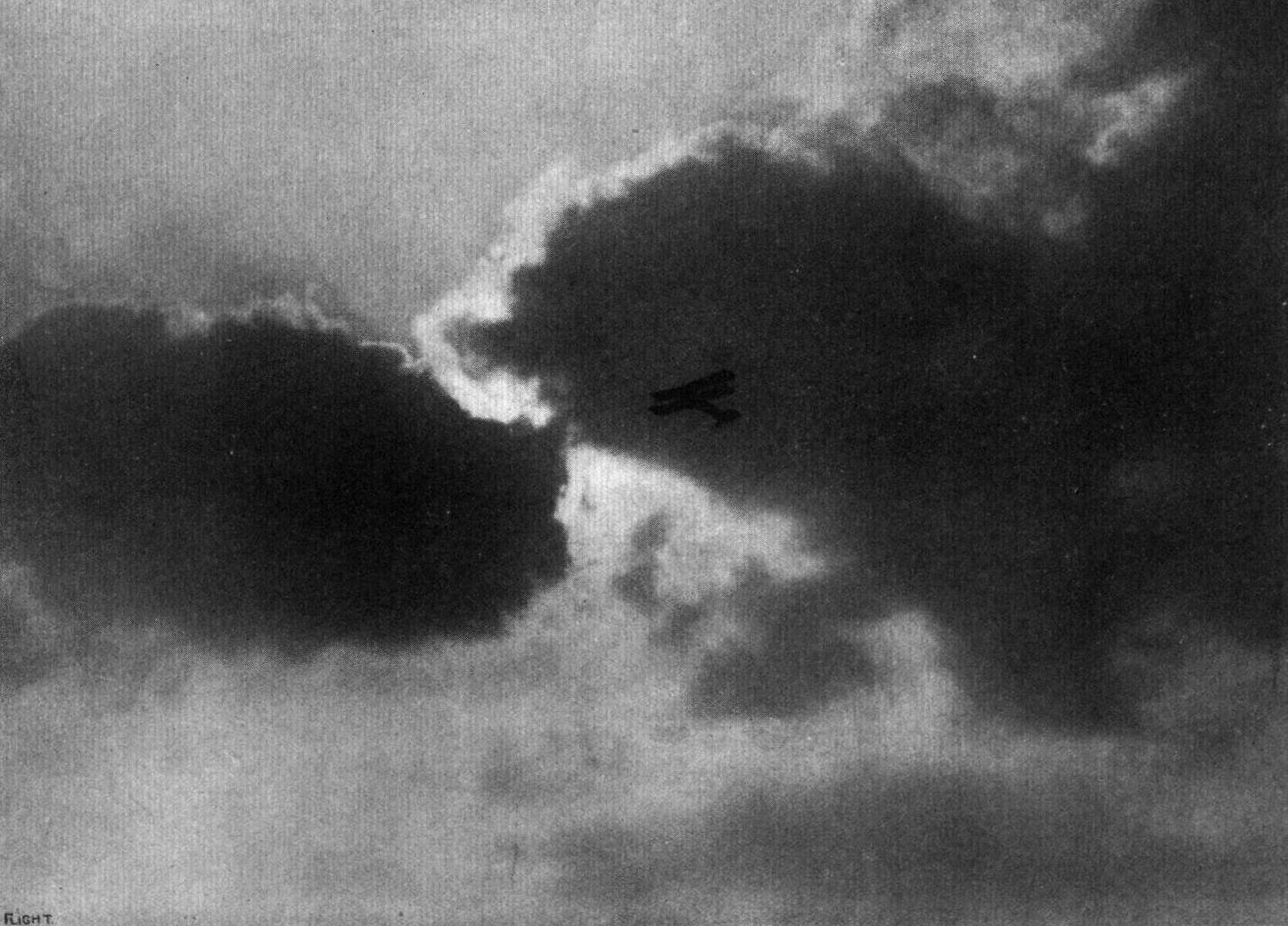
A silhouette against the clouds at Hendon of J. L. Hall on the Avro.
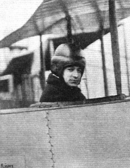
Mr. J. L. Hall in the pilot's seat of the Avro at Hendon.
Mr. C. F. Lan-Davis in the Avro at Hendon.
Mr. J. L. Hall takes Miss Elsie Spencer, who is so successfully appearing in the "Marriage Market" at Daly's Theatre, for a flight at Hendon on his 50 h.p. Avro.
Flight, March 14, 1914.
WHAT THERE WILL BE TO SEE AT OLYMPIA.
THE EXHIBITS.
Avro (A. V. Roe and Co.). (64.).
THIS well-known firm will exhibit three machines, all of which are fitted with 80 h.p. Gnome engines - a tractor hydro-aeroplane, a fighting biplane, and a scout tractor. The first mentioned has already proved its value as a fast machine with a wide speed range and excellent climbing capabilities, and is so familiar to our readers as a land machine, a description of which appeared in FLIGHT for December 6th last, that it is unnecessary to discuss it further here. It was upon a machine of this type that Raynham established a British height record during last month. The aeroplane shown will, however, be provided with floats, for sea service, and various minor improvements have been recently incorporated in the design, notably in regard to the springing of the undercarriage and the floats, so that it will be worthy of close inspection.
<...>
Each of the above machines will be fitted with the Avro safety belt, concerning which there is ample evidence of the fact that it has been designed by a practical man. Its notable features are, that the aviator gets into and out of the belt by means of the quick-release devices, which are in duplicate - one on each side - thereby ensuring that it is in working order, and the ample depth of the front section of the belt, which precludes any possibility of internal injury resulting should the pilot be suddenly thrown forward.
Flight, March 21, 1914.
THE OLYMPIA EXHIBITION.
THE EXHIBITS.
AVRO (A. V. ROE AND CO.). (64.)
THREE machines of different types, all representing considerable departures in design from previous models, whilst at the same time retaining the good qualities that have established such an enviable reputation for this enterprising firm. Keenly alive to the various requirements of the Army and Navy, Mr. A. V. Roe has designed three entirely different types, each for a different purpose, one being a military biplane of the pusher type, and built with a view to meeting the demand for a machine affording the observer an unrestricted view, and also possessing facilities for the mounting of a gun if desired. The second machine is a small, fast, single-seater, designed for scouting purposes, whilst the third and last is a hydro-biplane. All three machines are fitted with 80 h.p. Gnome engines.
<...>
The 80 h.p. Seaplane is similar to the land machines as regards its wings and fuselage, but possesses some very interesting features in the method of springing the floats. These are carried on a structure of steel tubes, of which the outer members are bent downwards inside the floats, where they are attached to another tube by means of rubber shock absorbers in the manner shown in one of the sketches. The opening in the deck of the float through which the tubular strut passes is afterwards covered with a flexible cover made made of diver's twill, so that although the floats are free to move several inches up or down no water is admitted inside them.
The main floats, of which there are two, are of the non-stepped variety, and are also covered with diver's twill, which has been found to be more satisfactory than fabric, as it does not tear go easily, although it is undoubtedly somewhat heavy. The floats are divided by bulkheads into 11 watertight compartments, so that should one of them spring a leak the remaining ones would still possess sufficient buoyancy to keep the machine afloat. The pilot's and passenger's seats are arranged tandem fashion, the pilot controlling the machine from the rear seat by means of the usual Avro controls.
A small float protects the tail planes against contact with the water, whilst a small water rudder mounted just behind the tail plane on an extension of the rudder post enables the pilot to steer the machine at slow speeds on the water.
Common to all the three machines is an extremely neat instrument board of Avro design, comprising altimeter, clock, compass, air speed indicator and revolution indicator, and all the machines are furthermore fitted with the Avro safety belt, the design of which is already known to the majority of our readers.
Flight, May 22, 1914.
THE AERIAL DERBY.
THE PILOTS AND HOW TO RECOGNISE THE MACHINES.
No. 13. The 80 h.p. Avro Biplane
is of the tractor type, and has an all-enclosed fuselage. It may be recognized by its chassis, which has a single central skid and two wheels.
THE MACHINES AND HOW TO RECOGNISE THEM.
No. 13. The 80 h.p. Avro Biplane is very similar to the machine on which Mr. F. P. Raynham did his famous glide from Brooklands to Hendon. This machine is very fast and possesses a good speed range. The engine, which is mounted in the nose of the fuselage, is totally enclosed by an aluminium shield.
Flight, June 26, 1914.
Raynham and Salmet in Ireland.
LAST weekend Mr. F. P. Raynham and Mr. Salmet were giving exhibition flights on behalf of the Daily Mail in the North of Ireland. On Thursday of last week they were at Lurgan. Mr. Kaynham, on the Avro machine which he flew at Brooklands last year, but now converted to a waterplane, started from a small pond, while Salmet on his Bleriot started from an adjoining field. In spite of the fact that the whole place was surrounded by trees, making it very difficult to get out, both pilots carried a good many passengers during the day. On Friday Raynham and Salmet were flying during the afternoon, while during the evening they flew the 25 miles to Warrenpoint. Raynham followed the canal from Portadown, and took exactly an hour, but during one half the journey his motor was only firing on five cylinders, and he flew low down between the hills; there was also a strong wind blowing. On Saturday flights were made at Warrenpoint, Salmet starting from the Golf Links and Raynham from the Bay.

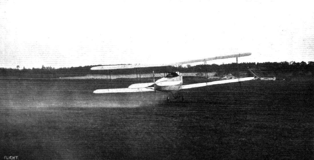
Mr. Lusteed, accompanied by a passenger, on the Daily Mail 80 h.p. Avro just off for Shoreham from Brooklands.

Pilot: Mr. H. Blackburn.
The Avro seaplane.
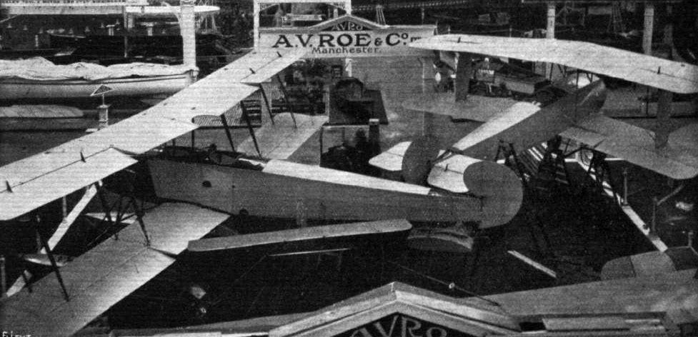
General view of the Avro stand.
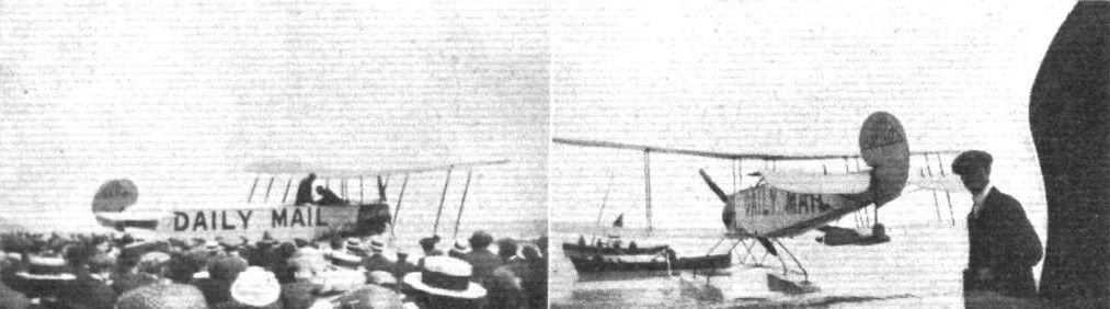
F. P. Raynham and his Avro waterplane at Scarborough in connection with the Daily Mail tours.
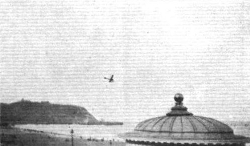
F. P. Raynham in flight at Scarborough on the Daily Mail Avro waterplane.
An Avro mascot on a car at Hendon on Aerial Derby Day.
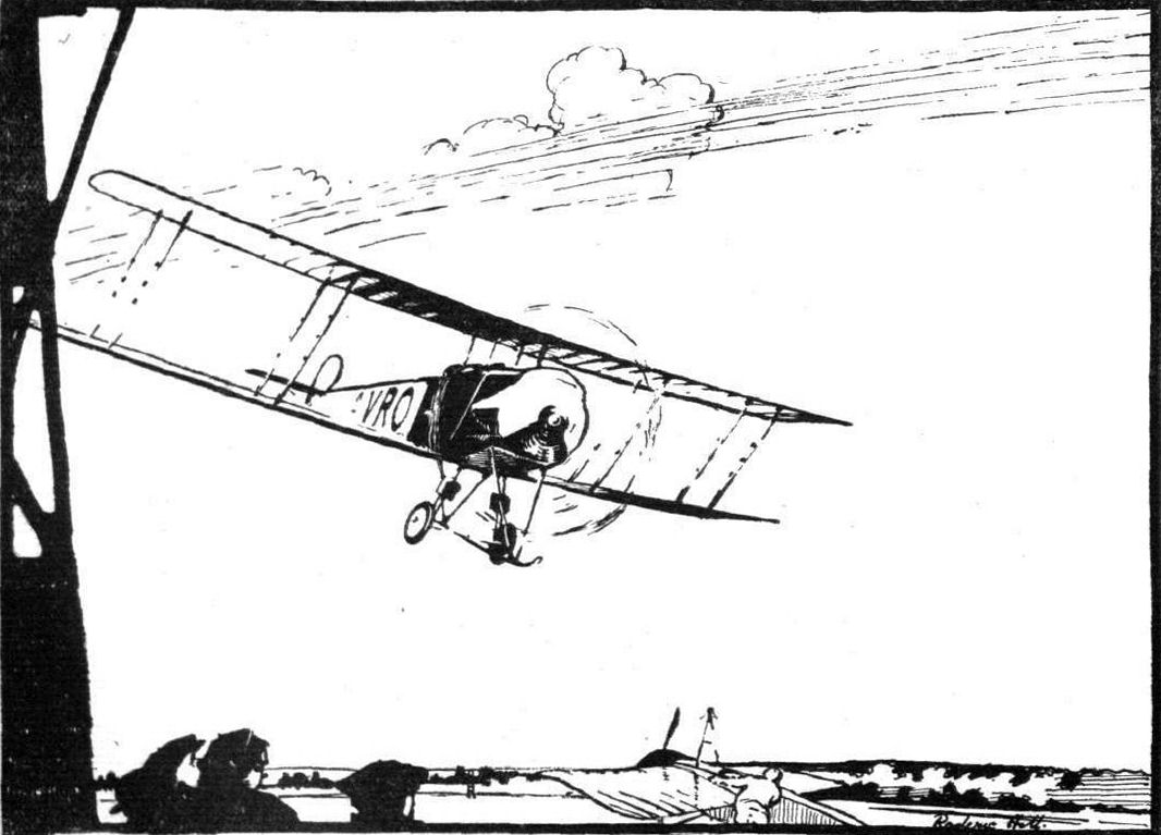
PASSING A PYLON AT HENDON AERODROME. - From an original drawing by Mr. Roderic Hill.
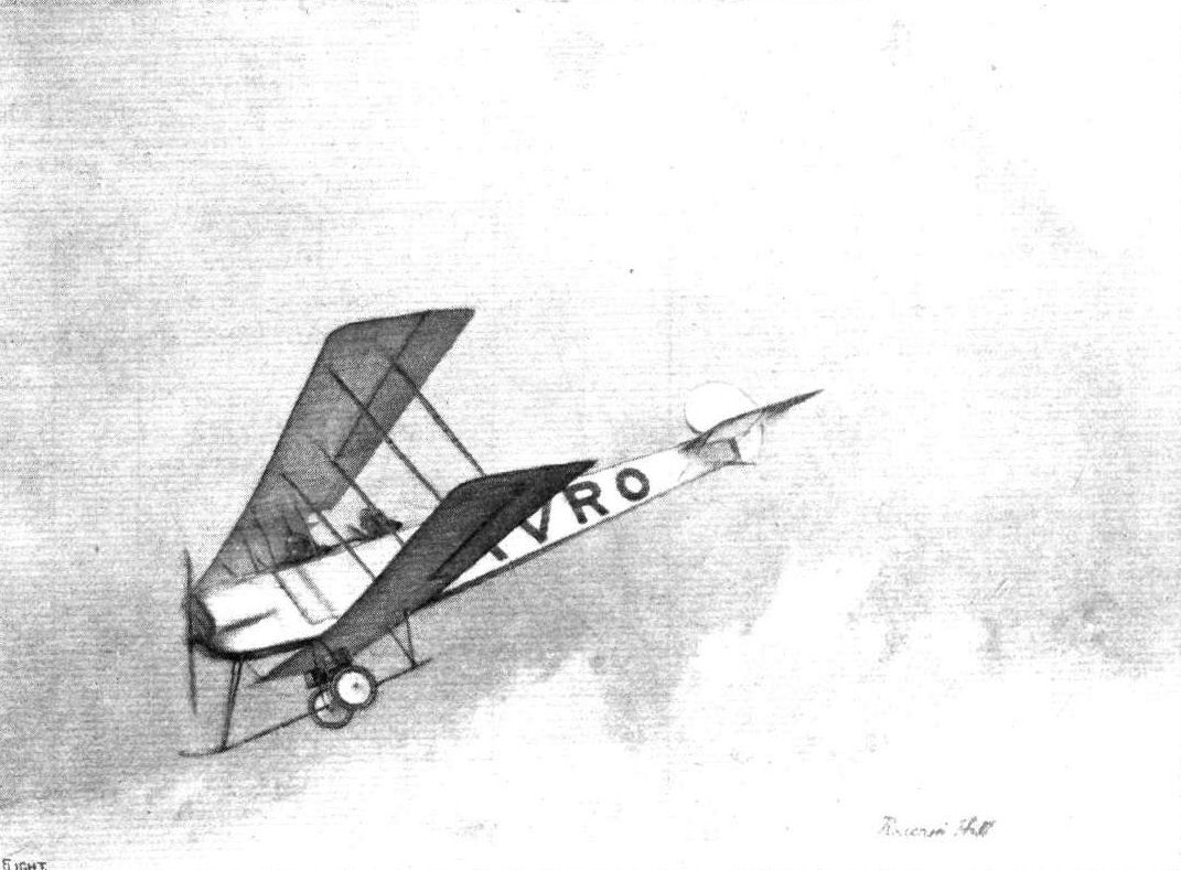
An impression of Raynham gliding on the 80 h.p. Avro. From an original drawing by Mr. Roderic Hill.
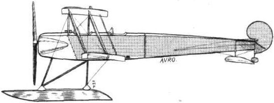
The 80 h.p. Avro seaplane.
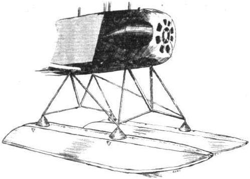
Chassis and main floats of the Avro seaplane.
The water rudder on the Avro seaplane.
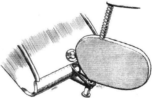
Detail of springing the floats on the Avro seaplane.
Flight, March 14, 1914.
WHAT THERE WILL BE TO SEE AT OLYMPIA.
THE EXHIBITS.
Avro (A. V. Roe and Co.). (64.).
THIS well-known firm will exhibit three machines, all of which are fitted with 80 h.p. Gnome engines - a tractor hydro-aeroplane, a fighting biplane, and a scout tractor.
<...>
The fighting biplane is a land machine of the "pusher" type, and has been recently introduced. The observer, or gunner, is seated well in front of the machine so as to give a wide range of vision for observation purposes, while sufficient fuel may be carried to last for 4 1/2 hours' continuous flight. The engine is encased in a streamline casing, as is also that on the former machine, and is supported in bearings fore and aft so as to obtain greater rigidity and avoid the use of an overhung engine.
<...>
Each of the above machines will be fitted with the Avro safety belt, concerning which there is ample evidence of the fact that it has been designed by a practical man. Its notable features are, that the aviator gets into and out of the belt by means of the quick-release devices, which are in duplicate - one on each side - thereby ensuring that it is in working order, and the ample depth of the front section of the belt, which precludes any possibility of internal injury resulting should the pilot be suddenly thrown forward.
Flight, March 21, 1914.
THE OLYMPIA EXHIBITION.
THE EXHIBITS.
AVRO (A. V. ROE AND CO.). (64.)
THREE machines of different types, all representing considerable departures in design from previous models, whilst at the same time retaining the good qualities that have established such an enviable reputation for this enterprising firm. Keenly alive to the various requirements of the Army and Navy, Mr. A. V. Roe has designed three entirely different types, each for a different purpose, one being a military biplane of the pusher type, and built with a view to meeting the demand for a machine affording the observer an unrestricted view, and also possessing facilities for the mounting of a gun if desired. The second machine is a small, fast, single-seater, designed for scouting purposes, whilst the third and last is a hydro-biplane. All three machines are fitted with 80 h.p. Gnome engines.
The 80-h.p. Military Biplane is of more or less standard design for this type of machine, as regards the general disposition of its component parts, but its designer has managed to incorporate in it numerous detail innovations. The nacelle, which is very wide and deep, is built up in the usual way of four ash longerons, connected by struts and cross members of spruce, strengthened in places by steel tubes. Inside this nacelle are arranged the pilot's and passenger's seats, tandem fashion, the pilot occupying the rear seat, so that the observer has a clear view, while it is possible to have a gun mounted on the nose of the nacelle. The controls are of the usual Avro type, consisting of a vertical lever mounted on a transverse rocking shaft, from which cables are taken to the various control organs. The ailerons are operated by a tide-to side movement of the lever, while a to-and-fro movement actuates the elevator. A pivoted foot-bar controls the rudder.
Behind the pilot's seat, and just in front of the engine, are the petrol and oil tanks, which have a capacity sufficient for a continuous flight of 4 1/2 hours. The engine, which is mounted on double bearings in the rear of the nacelle, is almost entirely covered in by an aluminium shield secured to four tubular extensions of the nacelle longerons. At their rear extremities where they converge, these extensions carry one of the engine bearers, the other being formed by a pressed steel frame mounted on the nacelle proper.
For a machine of the pusher type the chassis is rather unusual, it being in fact exactly similar to the chassis fitted to the Avro tractor machines. It consists of a single central ash skid carried on two pairs of steel tube struts, and two wheels sprung in the usual way by means of rubber shock absorbers attached to the T pieces of the wheel struts. In order to diminish head resistance, the shock absorbers have been enclosed in streamline aluminium casings.
The tail planes are similar to those of the tractor machines, the mounting of the fixed tail plane, however, being rather unusual, for the tail plane is not mounted on top of the tail booms, as is usually the case, but encloses the rear portion of the booms. In order to facilitate dismantling, the portion of the tail booms which is enclosed by the tail plane, is hinged to the remainder of the tail booms by a joint immediately in front of the tail plane, and the necessary rigidity at this point is obtained by cable bracing to the rudder post.
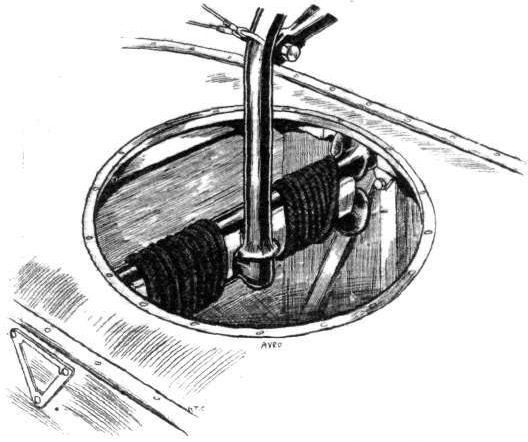
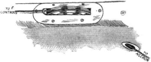
The main planes are of standard Avro type, except that the dihedral angle does not extend throughout the whole length of the planes, the central portion out to the first pair of struts being straight, so that only the outer portion of the wings are set at a dihedral angle. The method of carrying the aileron cables to the crank levers is rather unusual, and is illustrated by one of the accompanying sketches. It will be seen that the pulley has been placed inside instead of on top of the wing, the cable passing through a small opening in the lower surface of the wing.
<...>
Common to all the three machines is an extremely neat instrument board of Avro design, comprising altimeter, clock, compass, air speed indicator and revolution indicator, and all the machines are furthermore fitted with the Avro safety belt, the design of which is already known to the majority of our readers.
WHAT THERE WILL BE TO SEE AT OLYMPIA.
THE EXHIBITS.
Avro (A. V. Roe and Co.). (64.).
THIS well-known firm will exhibit three machines, all of which are fitted with 80 h.p. Gnome engines - a tractor hydro-aeroplane, a fighting biplane, and a scout tractor.
<...>
The fighting biplane is a land machine of the "pusher" type, and has been recently introduced. The observer, or gunner, is seated well in front of the machine so as to give a wide range of vision for observation purposes, while sufficient fuel may be carried to last for 4 1/2 hours' continuous flight. The engine is encased in a streamline casing, as is also that on the former machine, and is supported in bearings fore and aft so as to obtain greater rigidity and avoid the use of an overhung engine.
<...>
Each of the above machines will be fitted with the Avro safety belt, concerning which there is ample evidence of the fact that it has been designed by a practical man. Its notable features are, that the aviator gets into and out of the belt by means of the quick-release devices, which are in duplicate - one on each side - thereby ensuring that it is in working order, and the ample depth of the front section of the belt, which precludes any possibility of internal injury resulting should the pilot be suddenly thrown forward.
Flight, March 21, 1914.
THE OLYMPIA EXHIBITION.
THE EXHIBITS.
AVRO (A. V. ROE AND CO.). (64.)
THREE machines of different types, all representing considerable departures in design from previous models, whilst at the same time retaining the good qualities that have established such an enviable reputation for this enterprising firm. Keenly alive to the various requirements of the Army and Navy, Mr. A. V. Roe has designed three entirely different types, each for a different purpose, one being a military biplane of the pusher type, and built with a view to meeting the demand for a machine affording the observer an unrestricted view, and also possessing facilities for the mounting of a gun if desired. The second machine is a small, fast, single-seater, designed for scouting purposes, whilst the third and last is a hydro-biplane. All three machines are fitted with 80 h.p. Gnome engines.
The 80-h.p. Military Biplane is of more or less standard design for this type of machine, as regards the general disposition of its component parts, but its designer has managed to incorporate in it numerous detail innovations. The nacelle, which is very wide and deep, is built up in the usual way of four ash longerons, connected by struts and cross members of spruce, strengthened in places by steel tubes. Inside this nacelle are arranged the pilot's and passenger's seats, tandem fashion, the pilot occupying the rear seat, so that the observer has a clear view, while it is possible to have a gun mounted on the nose of the nacelle. The controls are of the usual Avro type, consisting of a vertical lever mounted on a transverse rocking shaft, from which cables are taken to the various control organs. The ailerons are operated by a tide-to side movement of the lever, while a to-and-fro movement actuates the elevator. A pivoted foot-bar controls the rudder.
Behind the pilot's seat, and just in front of the engine, are the petrol and oil tanks, which have a capacity sufficient for a continuous flight of 4 1/2 hours. The engine, which is mounted on double bearings in the rear of the nacelle, is almost entirely covered in by an aluminium shield secured to four tubular extensions of the nacelle longerons. At their rear extremities where they converge, these extensions carry one of the engine bearers, the other being formed by a pressed steel frame mounted on the nacelle proper.
For a machine of the pusher type the chassis is rather unusual, it being in fact exactly similar to the chassis fitted to the Avro tractor machines. It consists of a single central ash skid carried on two pairs of steel tube struts, and two wheels sprung in the usual way by means of rubber shock absorbers attached to the T pieces of the wheel struts. In order to diminish head resistance, the shock absorbers have been enclosed in streamline aluminium casings.
The tail planes are similar to those of the tractor machines, the mounting of the fixed tail plane, however, being rather unusual, for the tail plane is not mounted on top of the tail booms, as is usually the case, but encloses the rear portion of the booms. In order to facilitate dismantling, the portion of the tail booms which is enclosed by the tail plane, is hinged to the remainder of the tail booms by a joint immediately in front of the tail plane, and the necessary rigidity at this point is obtained by cable bracing to the rudder post.
The main planes are of standard Avro type, except that the dihedral angle does not extend throughout the whole length of the planes, the central portion out to the first pair of struts being straight, so that only the outer portion of the wings are set at a dihedral angle. The method of carrying the aileron cables to the crank levers is rather unusual, and is illustrated by one of the accompanying sketches. It will be seen that the pulley has been placed inside instead of on top of the wing, the cable passing through a small opening in the lower surface of the wing.
<...>
Common to all the three machines is an extremely neat instrument board of Avro design, comprising altimeter, clock, compass, air speed indicator and revolution indicator, and all the machines are furthermore fitted with the Avro safety belt, the design of which is already known to the majority of our readers.
The 80 h.p. Avro biplane.
The aileron pulley in the Avro pusher.
Flight, September 18, 1914.
THE "ROUND BRITAIN" MACHINES.
THE machine which was numbered 7 in the Circuit of Britain, and for which Mr. F. P. Raynham had been nominated pilot, was
The Avro Seaplane.
No great departures from standard Avro practice are to be found in this machine except, of course, such alterations as have been necessitated by the substitution of a Sunbeam engine for the Gnome with which Avro biplanes have been usually equipped hitherto.
The fuselage is of the standard type, of rectangular section, and is built up of four longerons of ash connected by struts and cross members of ash and spruce. Three-ply wood stiffening pieces are screwed to the longerons, which by this means can be kept comparatively thin without sacrificing the necessary strength. The deck of the fuselage is in the form of a turtle back, whilst the bottom is flat. In front the fuselage is sufficiently deep to totally enclose the 150 h.p. Sunbeam engine, which is mounted on strong bearers suitably connected up to the lower longerons. The exhaust pipes are taken to a funnel projecting up above the upper main planes so that there is no danger of the exhaust gases causing pilot and passenger any discomfort, by being blown back in their faces.
The two seats, which are of the bucket type, are arranged in tandem, the pilot occupying the rear seat. Dual controls are fitted, so that either of the occupants may pilot the machine in turn. Ailerons and elevator are operated by means of rotatable hand wheels mounted on vertical columns, to which are connected the elevator control cables. Steering is effected by pivoted foot bars. Between the passenger's seat and the engine are arranged the petrol and oil tanks, which have a capacity of 52 galls., or sufficient for a flight of 4 1/2 hours' duration.
The main planes are of the usual Avro section, and are characterised by a very pronounced overhang of the top plane. Lift cables run to various points on these extensions from the lower ends of the outer inter-plane struts, whilst the top bracing wires are taken to king posts above the plane. Both upper and lower main planes are set at a very pronounced dihedral angle, thus helping to provide the necessary fin area to balance the side area of the floats. Ailerons are fitted to the top plane only, but as they are of large area, and the machine is, moreover, to a great extent inherently stable laterally, there is probably an ample amount of lateral control. Four pairs of spruce struts separate the main planes in addition to the two pairs of fuselage struts, and cable bracing provides the necessary rigidity.
Tail planes of the usual Avro type are fitted at the rear end of the fuselage. A flat, non-lifting stabilizing plane is bolted to the sides of the fuselage, to which it is further stayed by means of two struts running to the lower longerons. A divided elevator is hinged to the trailing edge of the stabilizing plane, and a balanced rudder pivots round the tubular extension of the stern post of the fuselage. The lower end of this tubular rudder post carries a small rudder used for steering when the machine is taxying on the surface of the sea. A flat-bottomed rectangular section float, supported on four steel tubes coming down from the lower longerons of the fuselage, takes the weight of the tail planes when at rest.
The main chassis is similar in type to that of previous Avro seaplanes, and is chiefly characteristic on account of the method of springing the floats. From the accompanying illustrations, it will be seen that the floats are supported on an "M"-form structure of steel tubes, as seen from in front. Transverse steel tubes connect the lower points of the M to provide lateral stiffness. Immediately above the floats the tubular chassis struts are bent downwards, and carry at their lower ends, which project down inside the floats, cross-pieces to which the shock-absorbers are attached.
The two main floats, which are pitched 9 ft. apart, are of rectangular section, and are provided with a single step, occurring approximately under the centre of pressure of the wings. They are very strongly built, and as they have not been unduly lightened (each of them weighs 200 lbs.), they may be relied upon to stand up to even a comparatively rough sea. The openings through which pass the chassis struts are covered with canvas flaps, forming a waterproof, and at the same time flexible, cover over the openings. Small wing tip floats are fitted to the lower plane under the outer pair of inter-plane struts.
The weight of the machine fully loaded, including pilot, passenger and fuel for 4 1/2 hours, is 2,800 lbs., and the loading works out at about 5 lbs. per sq. ft. A speed of 70 m.p.h. is anticipated.
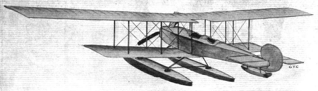
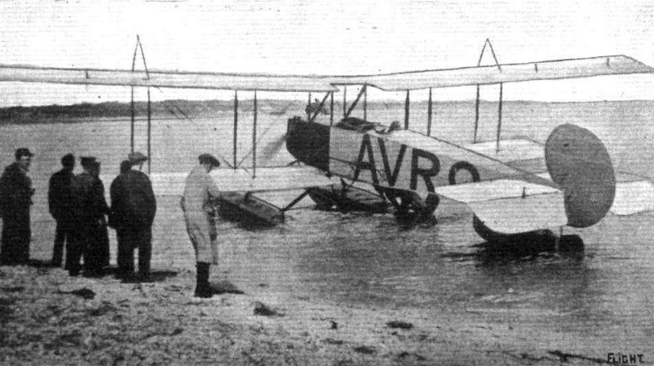
The 150 h.p. Sunbeam-engined Avro seaplane which was to have taken part tin the "Circuit of Britain" race, at Calshot, July 1914.
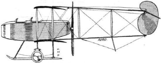
ROUND BRITAIN MACHINES, No. 7. - The Avro biplane.
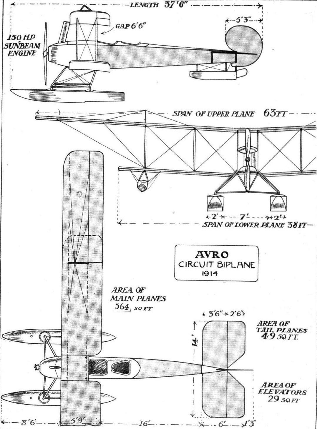
ROUND BRITAIN MACHINES, No. 7. - The Avro biplane. Plan, side and front elevations to scale.
Flight, March 14, 1914.
WHAT THERE WILL BE TO SEE AT OLYMPIA.
THE EXHIBITS.
Avro (A. V. Roe and Co.). (64.),
THIS well-known firm will exhibit three machines, all of which are fitted with 80 h.p. Gnome engines - a tractor hydro-aeroplane, a fighting biplane, and a scout tractor.
<...>
The "tabloid" single-seater scout, the latest production of Messrs. Roe, embodies several novel features, and is an excellent example of modern high-efficiency design, as is evident from the remarkably wide speed variation which is claimed for it. The wings are set back at the tips, so as to enhance the stability of the machine, while the unique system of bracing employed enables a number of wires (which are anchored in such a manner that no matter how the centre of pressure upon the wings may move, the loads are taken by both spars) to be dispensed with, thereby reducing the head resistance to some extent. This machine is fitted with air brakes, and, it is stated, may be dismantled and re-erected in a few minutes. The landing chassis is similar in construction to that on the 80 h.p. tractor land machine. The engine is an 80 h.p. "monosoupape" Gnome.
Each of the above machines will be fitted with the Avro safety belt, concerning which there is ample evidence of the fact that it has been designed by a practical man. Its notable features are, that the aviator gets into and out of the belt by means of the quick-release devices, which are in duplicate - one on each side - thereby ensuring that it is in working order, and the ample depth of the front section of the belt, which precludes any possibility of internal injury resulting should the pilot be suddenly thrown forward.
Flight, March 21, 1914.
THE OLYMPIA EXHIBITION.
THE EXHIBITS.
AVRO (A. V. ROE AND CO.). (64.)
THREE machines of different types, all representing considerable departures in design from previous models, whilst at the same time retaining the good qualities that have established such an enviable reputation for this enterprising firm. Keenly alive to the various requirements of the Army and Navy, Mr. A. V. Roe has designed three entirely different types, each for a different purpose, one being a military biplane of the pusher type, and built with a view to meeting the demand for a machine affording the observer an unrestricted view, and also possessing facilities for the mounting of a gun if desired. The second machine is a small, fast, single-seater, designed for scouting purposes, whilst the third and last is a hydro-biplane. All three machines are fitted with 80 h.p. Gnome engines.
<...>
Of the remaining two machines on this stand.
The 80 h.p. Single-seater Scout is perhaps the more interesting since it embodies so many novel features. The chassis, fuselage and tail planes of this biplane follows standard Avro practice throughout, and are similar in every way to those of the tractor biplane described in FLIGHT for December 6th last. It is mainly in the design of the wings and their bracing that this machine is remarkable.
The wings have a very pronounced backward slope so as to increase the stability, which latter is further enhanced by the usual dihedral angle. In section the planes are remarkable, in that they are absolutely flat on the under surface, whilst the upper surface is cambered in the usual way. This wing section is apparently one of the important factors for the very high speeds claimed for the machine, one of the others being the reduction of head resistance in the wing bracing. Only one pair of struts on each side separate the main planes, and a streamline casing around these struts further reduces the head resistance to that of a single strut on each side. The wing bracing is effected by two stranded cables running from the top and bottom respectively of the fuselage struts to a steel tube connecting the main spars at the point where these join the struts. Thus when the centre of pressure travels backwards and forwards, the load is always taken by both spars through the intermediary of the steel tube connecting them. Ailerons are hinged to the outer trailing edges of both planes, whilst air brakes for pulling the machine up quickly on landing are formed by pivoting the rear portion of the wing near the body. For checking the speed of the machine on alighting the pilot turns these air brakes by means of a lever until they are broadside on with regard to the line of flight.
<...>
Common to all the three machines is an extremely neat instrument board of Avro design, comprising altimeter, clock, compass, air speed indicator and revolution indicator, and all the machines are furthermore fitted with the Avro safety belt, the design of which is already known to the majority of our readers.
Flight, May 22, 1914.
THE AERIAL DERBY.
THE PILOTS AND HOW TO RECOGNISE THE MACHINES.
No. 14. The 80 h.p. Avro Scout.
This machine will be easily recognized from the shape of its wings, which slope backwards so as to form a V.
THE MACHINES AND HOW TO RECOGNISE THEM.
No. 14. The 80 h.p. Avro Scouting Biplane was, it will be remembered, exhibited at the last Olympia Aero Show. It is mainly characteristic on account of its main planes, which slope backwards so as to form a V, as seen in plan. This machine, which was fitted at the time of the Show with air-brakes for the purpose of reducing the speed when landing, is expected to be very fast, as the angle of incidence is very small and the planes are perfectly flat on the under sutface.
Flight, June 12, 1914.
THE 80 H.P. AVRO SCOUT.
THE subject of our scale drawings this week - the 80 h.p. Avro Scout - made its first public appearance at Hendon on May 23rd last, piloted by Mr. F. P. Raynham. This machine had, we understand, only been tested on two short flights previously, so that, in view of the fact that she presents such considerable departures from standard design, her performances were very good indeed. From Mr. A. V. Roe we learn that the machine was not quite so fast as he had expected, but this was probably partly due to the fact that the engine was not running particularly well. As far as one was able to judge, the speed range was very considerable, and without knowing actual figures we should think that the maximum speed was over 90 m.p.h. The climbing capabilities also seemed very good indeed, Mr. Raynham taking the machine up at what looked like an alarmingly steep angle, but which was in reality probably about 30#.
Constructionally, this machine differs little, at least as regards the fuselage, from standard Avro practice. It is mainly in the design and construction of the wings that innovations are to be found. Most noticeable among these is the way in which the main planes slope backwards so as to form a V as seen in plan. Only one pair of struts on each side separate the main planes, and these struts are cross-braced and covered in with fabric to form a unit, thereby reducing head resistance to that of a single strut. The wing bracing has been reduced to an absolute minimum since only one pair of cables on each side provide the necessary rigidity. At their outer ends these cables are attached, by means of a steel clip, to a steel tube of two inches diameter, built into the wing and joining the two spars. Thus, for any position of the centre of pressure the lift is always taken by both spars through the intermediary of the steel tube.
In section the wings are somewhat unusual in that they are perfectly flat on the under surface, whilst the top surface is cambered in the usual way. In addition to the backward slope of the wings, these are set at a very pronounced dihedral angle in order to increase lateral stability. Ailerons are fitted to both upper and lower planes, but the air brakes with which this machine was fitted at the Olympia Aero Show have been temporarily rendered immovable by securing them to the rear spar with an aluminium strip, probably owing to the fact that there has not yet been time for experiments with the action of these brakes.
The engine, an 80 h.p. Gnome, is mounted between double bearings, and is almost totally enclosed by an aluminium shield. Some trouble was experienced in keeping the engine cool so that it is possible that a few alterations will be effected in order to provide more efficient cooling. The chassis is of the usual Avro type, and appears to possess an enormous amount of flexibility. The fuselage, as has been already said, differs but little from those of the larger Avro biplanes. The four ash longerons are strengthened by triangular pieces of three-ply wood tacked on. The pilot is accommodated in a very comfortable bucket seat, and has in front of him a neat set of instruments mounted on an Avro instrument board. Control is by means of a single central column mounted on a transverse rocking shaft, which carries crank-levers for the elevator. The rudder is operated by a pivoted foot-bar in the usual fashion. Mounted on the rear-end of the fuselage are the tail planes, which are of the usual Avro type, consisting of a fixed tail plane, to the trailing edge of which is hinged a divided elevator, and a balanced rudder. A small laminated steel skid protects the tail planes against contact with the ground.
It is difficult at the present juncture to express an opinion as to the merits or otherwise of this machine, but judging from her behaviour during her first flight in public, and considering the few tests that have been made with her up to now, she must be said to be very promising, and Messrs. A. V. Roe and Co. are to be heartily congratulated on their continued determination to introduce new departures in design.
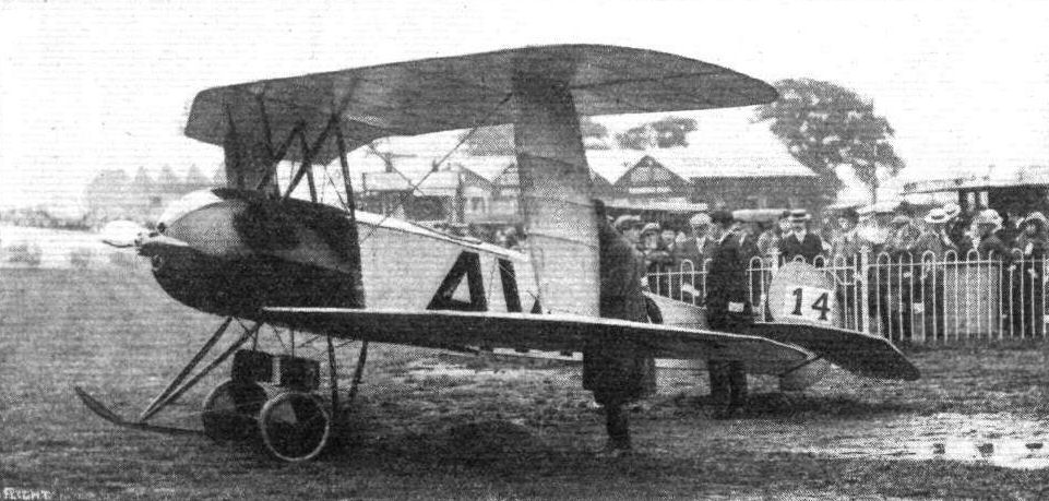
Avro Arrowscout at Hendon with F. P. Raynham standing by the tail.

The Avro Scouting Biplane (No. 14).
General view of the Avro stand.

The Avro scout.
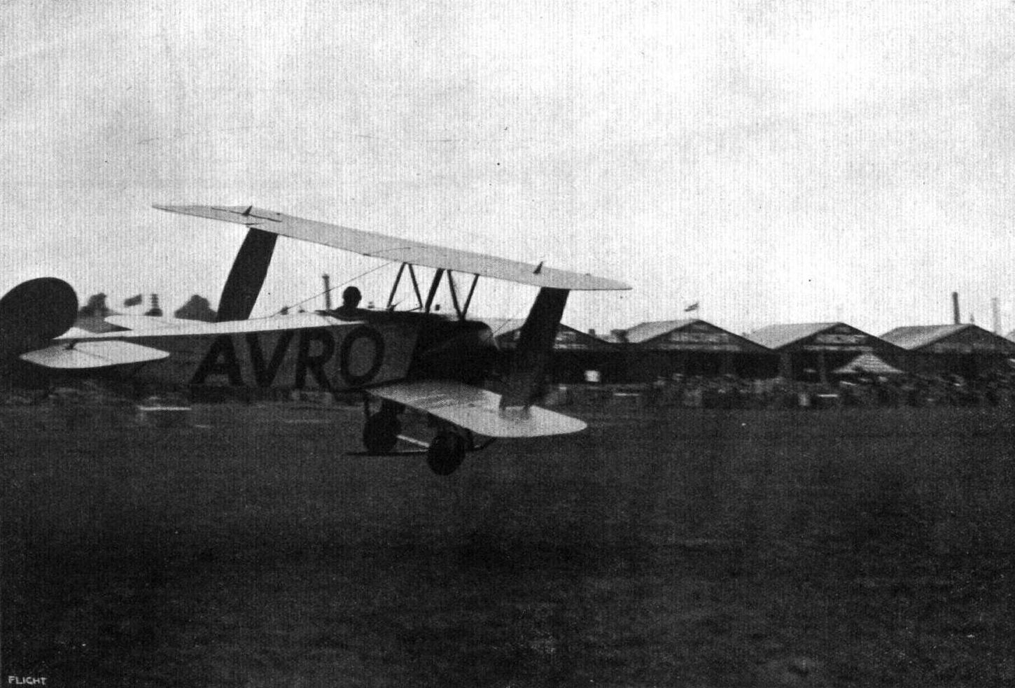
Mr. Raynham, in the Avro scout, just getting off at Hendon Aerodrome,
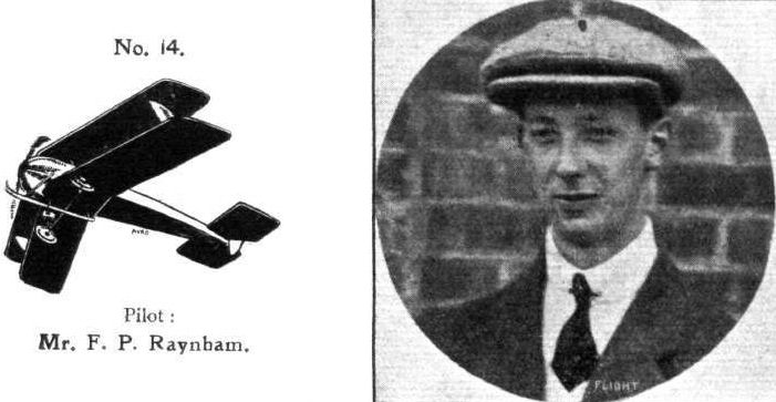
Pilot: Mr. F. P. Raynham.

The 80 h.p. Avro tractor biplane.

The air brake on the Avro scout.
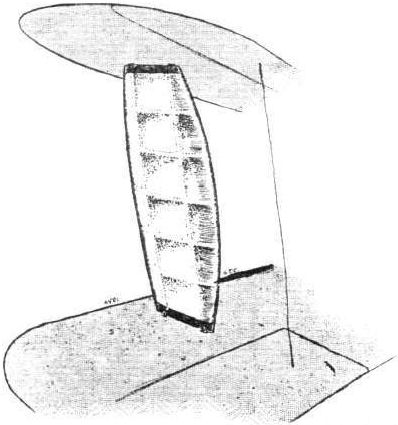
The streamline casing round the plane struts of the Avro scout.
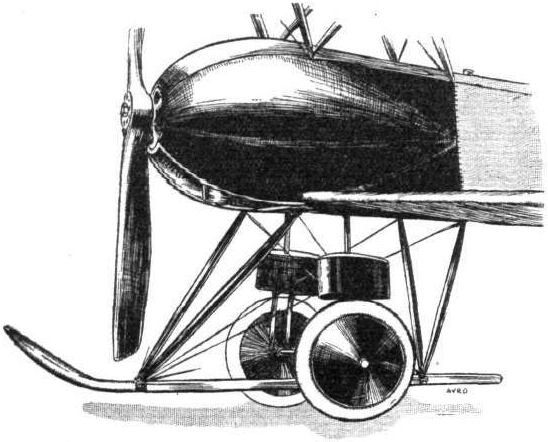
Chassis and engine housing on Avro scout.
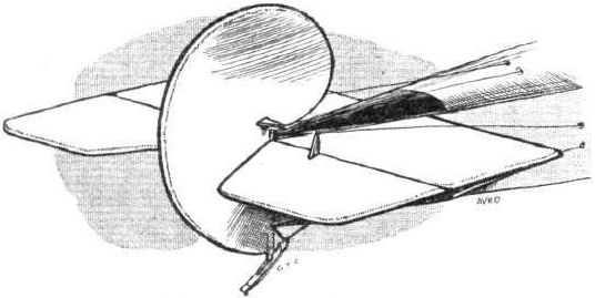
Tall planes on Avro scout.
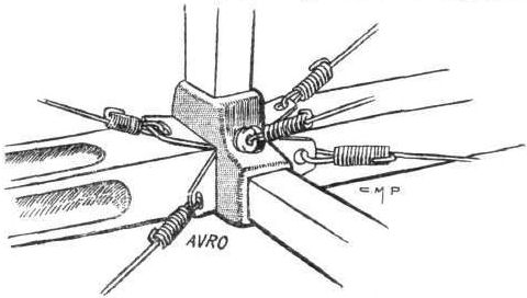
A fuselage joint on the Avro biplane.

THE AVRO SCOUT BIPLANE. - Plan, side and front elevations to scale.
Flight, March 14, 1914.
WHAT THERE WILL BE TO SEE AT OLYMPIA.
THE EXHIBITS.
Blackburn (Blackburn Aeroplane Co.). (63.)
THE exhibit on this stand will consist of the 80 h.p. Gnome Blackburn monoplane, which has been specially built for high speed cross-country work. It will he of practically the same design of machine as was described in FLIGHT for December 27th last, when we noted that a similar machine had traversed a distance of 1,800 miles, and carried over 120 passengers during the preceding three months.
Every endeavour has been made in the design of this machine to reduce head resistance to a minimum, and to give the greatest comfort and safety to the pilot and passenger. The front part of the fuselage is covered in with sheet aluminium, and the engine is encased for about five-eighths of its circumference in an aluminium cowl, which is continued to the rear so as to form a scuttle dash, so that the exhaust or oil from the engine is prevented from blowing back upon the pilot or passenger, who are well screened from the wind. It is stated that the factor of safety used in the design of cables is not less than ten.
Flight, March 28, 1914.
THE OLYMPIA EXHIBITION.
THE EXHIBITS.
BLACKBURN (THE BLACKBURN AEROPLANE CO.).
THE monoplane exhibited by the Blackburn Aeroplane Co. is very similar to the machine sold to Dr. Christie, and fully described in our issue of December 27th, 1913. In the machine shown, no attempt has been made to piovide a very showy finish, but it is a thoroughly sound piece of work, and although it is by no means a particularly heavy machine, it gives the impression of being very strong.
Constructionally it follows fairly closely standard Blackburn practice, but the lines are now much more pleasing than were those of the earlier machines, and several detail improvements have been effected. The bearers for the engine - an 80 h.p. Gnome - have been modified, and the result is a much neater nose to the machine, whilst the engine bearers are probably as strong as were the old ones and certainly a good deal lighter. As before, the engine is mounted between double bearings, but the front bearer is formed in this machine by a horizontal U of channel steel continued along the front portion of the longerons. The engine is partly covered in by an aluminium shield, which prevents any oil from being blown back in the pilot's face.
The triangular section fuselage has been retained, and is built up of three longerons of ash and spruce with struts of the same material, whilst diagonal strips of wood forming a girder take the place of the usual internal cross wiring.
The pilot is accommodated in a very roomy and comfortable cockpit, and in front of him is the passenger's seat, in a separate cockpit. The old type Blackburn control has been replaced by one of a more standard type, consisting of a rotatable band wheel mounted on vertical column, which actuates the warp and elevator. The rudder is operated by a pivoted foot-bar.
The chassis consists of two stout ash skids supported on four vertical struts of the same material, and connected by two streamline steel tubes. The tubular axle is slung from the skids by rubber bands, and carries two wheels of the disc type.
The wings are built up of spruce webs wit h ash flanges over two ash spars of I section. The lift and drift is taken by heavy stranded cables running to the lower members of the chassis, and the warp cables, of which there are three, are secured to a very stout steel ring from which another cable runs over pulleys on the chassis to the corresponding ting on the other side. From the two rings the cable controlling the warp runs over pulleys to the control wheel. The upper bracing cables are secured to a pylon projecting above the fuselage covering. The front spars are secured in a strong wooden box forming a unit with the upper pylon, whilst the rear spars are hinged to the fuselage so that when the wings are warped the rear spar is not bent but simply swings round its pivot. The angle of the lift cables is particularly good owing to the comparatively high chassis which has always been one of the features of the Blackburn machines. The whole wing bracing system is immensely strong, and should inspire the pilot with absolute confidence.
Mounted on top of the fuselage is a stabilizing plane of roughly semi-circular shape to which is hinged the divided elevator. The rudder is hinged to a rudder post forming an extension of the stern post of the fuselage, and a small triangular vertical fin completes the tail unit. Mr. Blackburn is to be congratulated on the progress made during the last year or so. The machine as it stands now is thoroughly sound and quite equal to anything turned out by other monoplane constructors.
Various Blackburn propellers are also exhibited on this stand, and show that the Blackburn firm are able to turn out a highly finished article when they are so minded.

Harold Blackburn and passenger in the Type I as it was in November 1913 with rudder inscription and modified engine cowling. The tail-up attitude was provided by two gentlemen whose likenesses were obliterated from the original print.
The 80 h.p. Blackburn monoplane which will be among the exhibits. A machine of similar design, piloted by Mr. Blackburn, won the Inter-County Air Race held at the latter end of last year in Yorkshire.
The 80 h.p. Blackburn monoplane which will be among the exhibits. A machine of similar design, piloted by Mr. Blackburn, won the Inter-County Air Race held at the latter end of last year in Yorkshire.

The Blackburn monoplane.
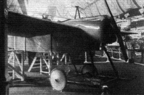
Chassis and engine housing of Blackburn monoplane.
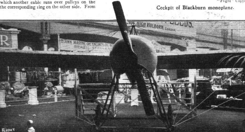
Front view of Blackburn monoplane.
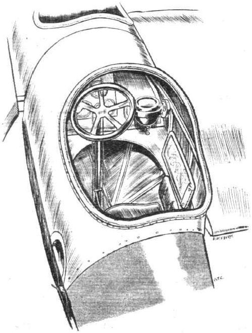
Cockpit of Blackburn monoplane.

The 80 h.p. Blackburn monoplane.
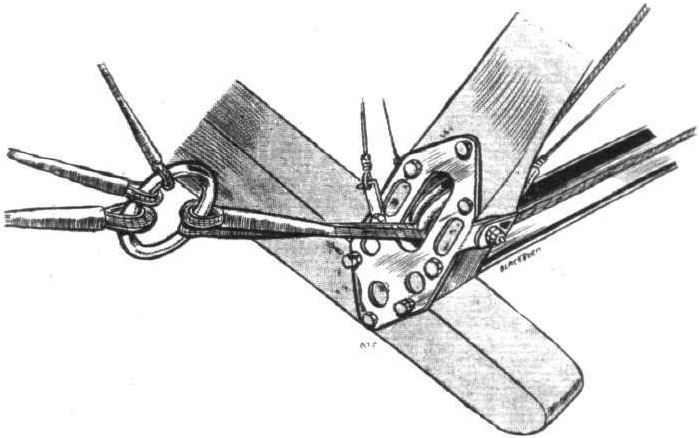
Pulleys and steel ring incorporated in warping system on Blackburn monoplane.
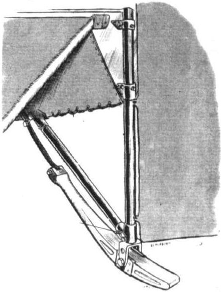
Blackburn tail skid.
Flight, September 25, 1914.
THE "ROUND BRITAIN" MACHINES.
THE machine which was officially numbered 8 in the Circuit of Britain, and for which Mr. Sydney Pickles had been nominated pilot, was
The Blackburn Tractor Seaplane.
Although being of the biplane type the latest Blackburn follows along the lines of the monoplanes previously produced by this firm. As seen from the side, the body of the seaplane greatly resembles that of the monoplanes, but constructionally it differs from the latter in that it is of rectangular section instead of the triangular section employed in the monoplanes. The four ash longitudinals converge towards the rear, where they join on to a vertical knife edge. Cross bracing is still by diagonal wooden strips instead of the more universally adopted wire bracing. A turtle back extends from the engine cowl back to the tail plane, and has openings cut in it for the pilot and passenger. These sit one behind the other in separate cockpits, with the pilot at the rear.
Petrol is carried in two tanks mounted on the upper longitudinals of the body; one in front of the pilot, containing 32 gallons, and a second one in front of the passenger, holding 21 gallons. The front tank is divided by a transverse partition, the front portion containing five gallons of oil, or sufficient for a flight of five hours' duration. The petrol tank in front of the pilot has its rear end sloping slightly forward to form a dash, on which are mounted a complete set of instruments, including revs, indicator, altimeter, compass, clock, &c.
The controls consist of a rotatable hand wheel mounted on a single, central, tubular column, which is, in turn, secured to a transverse rocking shaft, working in bearings on two longitudinal members inside the body. Rotation of the wheel operates the balancing flaps, a to-and-fro movement of the wheel and column actuates the elevator, and the rudder is controlled by a pivoted foot bar.
In the nose of the body is mounted the engine - a 130 h.p. Salmson-Canton-Unne motor driving a Blackburn propeller. An aluminium cowl encloses practically the whole of the engine, and extends back in the shape of a turtle-back, over the top of the body. The main planes, of which the lower one only is set at a dihedral angle, are characterized by having their trailing edge longer than the leading edge. Balancing flaps are hinged to the trailing edge of the top plane only. These are inter-connected by cables passing over pulleys on top of the upper plane, and running across to the corresponding pulleys on the other side. From the lower surface another series of cables pass from the balancing flaps to the control wheel. The main planes are braced internally and fitted with stout compression struts between the spars. Two pairs of interplane struts connect the planes on each side of the body, and cable bracing is employed.
At the rear of the fuselage is a set of tail planes, consisting of a cambered, fixed tail plane, a divided elevator, a vertical fin and a balanced rudder. A small float, supported from the body on four steel tubes, takes the weight of the tail planes when the machine is at rest. The control cables, which are all in duplicate, pass from crank-levers on the directional organs, through openings in the body, to the controls.
Carried on a structure of strong wood struts are the two main floats, which are of the stepped type. Near the nose the floats have a pronounced Vee bottom, which gradually flattens out towards the third step, which is flat in section, although having a marked camber, as seen from the side. The sides of the floats are flat and vertical, and a curved deck allows the water to run off quickly. The chassis struts, of which there are three to each float, run from the junction of the main spars to the body and from a point immediately under the engine, respectively. The lower ends of the struts are attached to transverse steel tubes, tying them together, and the floats are secured to the transverse tubes by steel clips, as seen in the accompanying illustrations.
The weight of the machine empty is 1,500 lbs. and loaded about 2,200 lbs. A speed range of from 45 to 75 m.p.h. is anticipated.
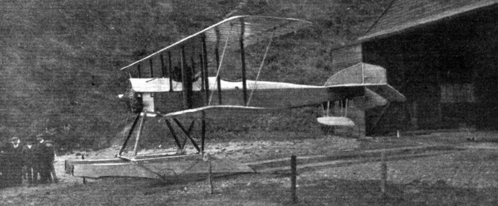
ROUND BRITAIN MACHINES, No. 8. - Side view of the Blackburn Tractor seaplane. The wheels shown do not form part of the chassis, but are merely used for running the machine down to the water.

Three-quarter view from behind of Blackburn tractor seaplane.
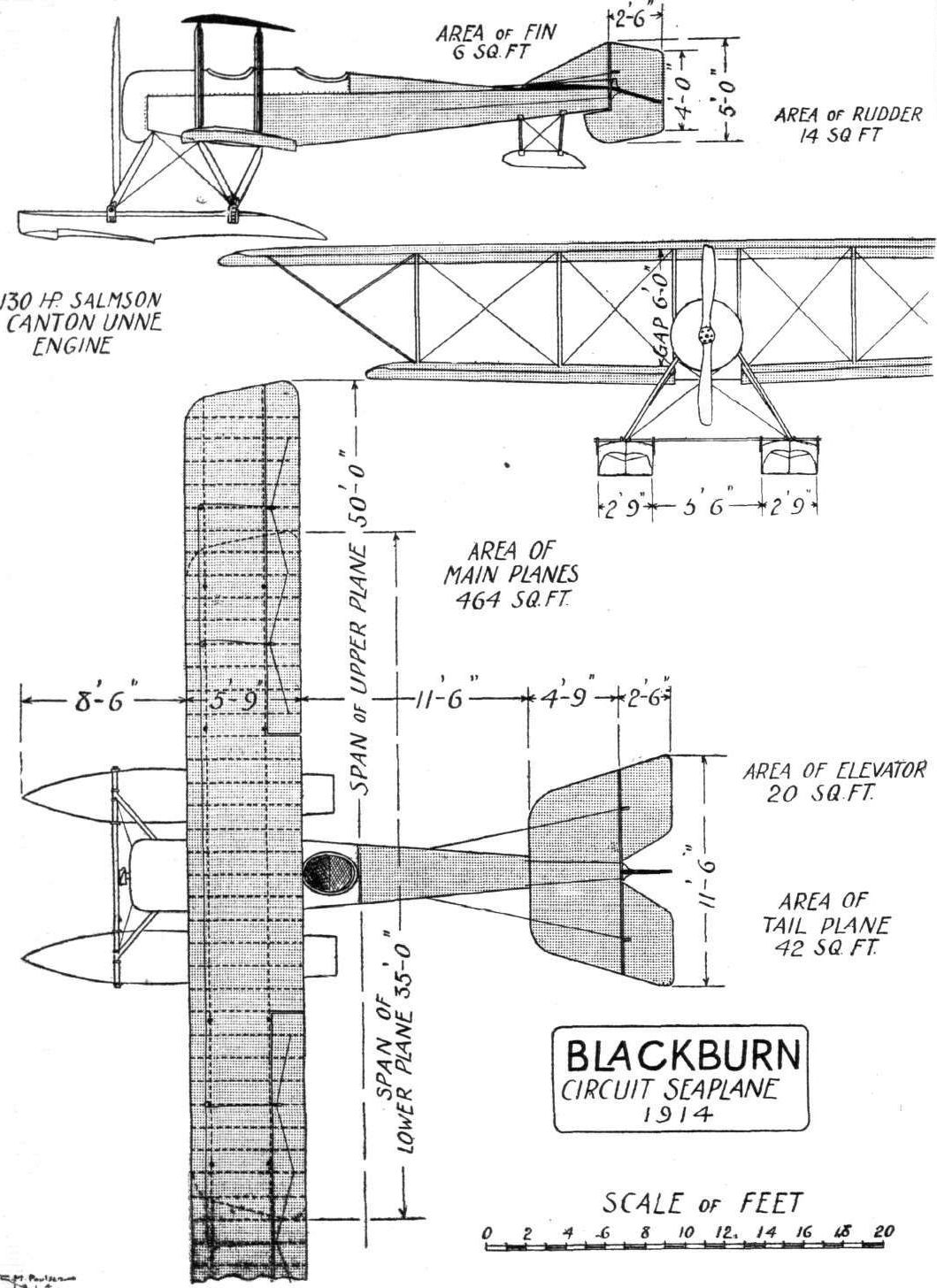
ROUND BRITAIN MACHINES, No. 8. - The Blackburn tractor biplane. Plan, side and front elevations to scale.
Flight, March 14, 1914.
WHAT THERE WILL BE TO SEE AT OLYMPIA.
THE EXHIBITS.
Bristol (British and Colonial Aeroplane Co., Ltd.). (43.)
THIS firm of constructors, who were our sole representative at the recent Paris Aero Exhibition, are showing two machines, one of which is a two-seater with the seats arranged in tandem, and the other a single-seater, as well as their travelling motor-repair workshop. Both machines exhibited are 80 h.p. Gnome-engined tractor biplanes, the engine on the two-seater being of the new Monosoupape type mounted upon supporting plates of pressed steel, and entirely enclosed in an aluminium shield that is continued forward in advance of the propeller for which it forms the boss and with which it rotates.
Special attention has been given in the design of the wings, which, on the single-seater machine, are all fitted with double-acting ailerons. The empennage of this machine is non-lifting, and the frames for this as well as those for the elevator flaps and rudder are of steel tubing, the fabric covering being sewn on. On the two-seater the empennage is set at a negative angle and is used as a directive organ. The landing chassis of the latter is of the standard Bristol type, but the single-seater machine has a special two-wheeled undercarriage. Sufficient petrol may be carried to give a flight lasting for 3 hours in the case of the single-seater and 5 hours for the two-seater.
The travelling workshop is fully equipped with every means necessary for the purpose of executing repairs to an aeroplane, and has been kept to the smallest possible dimensions. Winding gear, for the purpose of enabling the vehicle to wind itself or haul a trailer, is provided, as well as a dynamo of 50 amperes capacity at 65 volts, with suitably arranged switches for controlling the machine tools, which are driven by a separate electric motor. These machines include a lathe, band-saw, drilling machine, portable drill and a grinding machine, but a hand-operated shaping machine is also fitted. Increased floor space n obtained whilst the workshop is at rest, by dropping the two halves of each side door.
Flight, March 21, 1914.
THE OLYMPIA EXHIBITION.
THE EXHIBITS.
BRISTOL. (BRITISH AND COLONIAL AEROPLANE CO., LTD.)
THE two biplanes exhibited on this stand differ considerably from previous models, the two-seater bearing hardly any resemblance to its prototype shown at Olympia last year, whilst the small fast single-seater scouting machine may be said to be the first of a new type to be turned out by this firm.
In the 80 h.p. Two-seater Biplane an attempt has been made to provide a good streamline form of fuselage by adding curved super-and sub structures to the main rectangular portion and by continuing the engine cowl forward in the shape of a hemispherical nose-piece mounted on and revolving with the propeller boss. In order to provide better cooling, this nose-piece is louvred, so that although the engine is totally enclosed the cooling should present no difficulties. The engine, an 80 h.p. Gnome monosoupape, is mounted on overhung bearings in the nose of the fuselage, and drives directly the Bristol propeller. The fuselage is built up in the usual way of four longerons, which are of ash in the front portion, and of spruce, spindled down to an I-section, at the rear, connected by struts and cross-members of ash and spruce. The turtle back on top of the fuselage is constructed of three-ply wood up to a point behind the pilot's seat, whilst the rear portion of it is formed by longitudinal wooden stringers covered with fabric. The structure underneath the fuselage is formed in the same way by fabric-covered stringers.
The chassis is of the already well-known Bristol type, consisting of four struts carrying two skids, from which are in turn sprung the four wheels, the only noticeable alteration in the chassis appears to be that the rear pair of struts are now sloping backwards instead of coming straight down, an arrangement which, we feel inclined to think, would impose considerable strain on the diagonal cross-wiring. Now, as before, the chassis struts are made of spruce and the skids of ash, whilst the tubular steel axes are streamlined with wood.
The wings appear to be similar to those fitted on the machine exhibited at the Paris Show, and are of a peculiar section, being practically flat on the upper surface between the two main spars. By means of quickly detachable fittings the wings can be readily removed from the centre section for purposes of storage or transport. The main spars are attached to the fuselage by means of a steel clip and horizontal bolt, as illustrated by one of the accompanying sketches. Cane skids are fitted to the wing tips in order to protect them against contact with the ground. The pilot's and passenger's seats are arranged very comfortably, tandem fashion, in two separate cockpits, the pilot occupying the rear seat. The controls are of the usual Bristol type, consisting of a wheel mounted on a central column, for warp and elevator, whilst a pivoted foot-bar operates the rudder. In front of the pilot it an unusually neat instrument board, on which is mounted in addition to the usual set of instruments, an electric signalling device, consisting of a series of small electric bulbs marked in the following order: "Up," "right," "left," "circle," "steady," "return," "down," "land." By means of a series of buttons in the observer's cockpit, similarly marked, the observer can give the pilot orders unhampered by the noise of the engine.
The tail planes consist of a fixed tail plane, set at a negative angle of incidence, and to the trailing edge is hinged the undivided elevator, while it is surmounted by a small vertical fin to the trailing edge of which the rudder is hinged.
A tail skid of laminated wood similar to that fitted on the Paris Show machine protects the tail planes against contact with the ground.
<...>
Flight, May 22, 1914.
THE AERIAL DERBY.
THE PILOTS AND HOW TO RECOGNISE THE MACHINES.
No. 9. The 80 h.p. Bristol Biplane
will be somewhat difficult to distinguish from machine No. 13, the Avro biplane, but may be identified by its peculiar four-wheeled chassis.
THE MACHINES AND HOW TO RECOGNISE THEM.
No. 9. The 80 h.p. Bristol Biplane is a standard Bristol tractor machine, and is similar to the machines exhibited at the last Paris and Olympia Aero Shows. Although these machines have done a great amount of flying in the west of England, and on Salisbury Plain, they are not so well known to Londoners as they deserve to be, and should, therefore, be watched with interest by those of our readers who will watch the Aerial Derby, either from the starting place at Hendon Aerodrome or from one of the turning points.
Flight, August 7, 1914.
EDDIES.
The 80 h.p. Bristol tractor biplane purchased by Mr. Creagh is doing some very good work at Brooklands. On Thursday of last week Mr. Sippe went out for altitude accompanied by the owner of the machine. After being away beyond the eye of man for about an hour the "Bristol" was seen to be returning in beautiful spirals, and when she was sufficiently low it was also seen that the propeller was stopped. After executing some exceedingly small spirals and steeply banked turns, Mr. Sippe made a perfect landing without re-starting his engine. 11,000 feet was the total of this little climb.
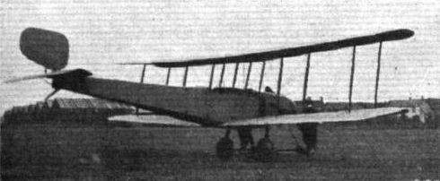
The graceful 80 h.p. Clerget-engined "Bristol" biplane at Brooklands purchased by Mr. Richard P. Creagh.
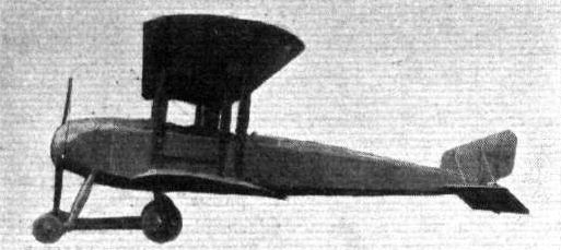
The Bristol Two-seater Biplane (No. 9).
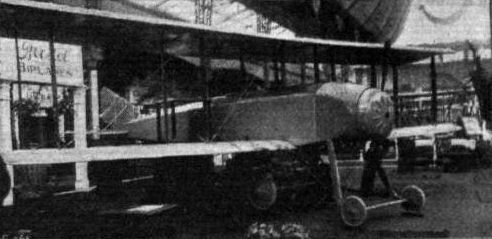
The Bristol tandem two-seater.
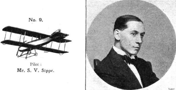
Pilot: Mr. S. V. Sippe.
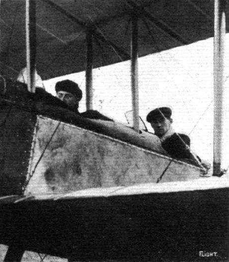
Messrs. Creagh and Sippe at Brooklands, looking a bit cold on their return to earth after reaching an altitude of 11,000 ft. on Mr. Creagh's Bristol. Needless to say, the cold did not extend to their lower extremities.
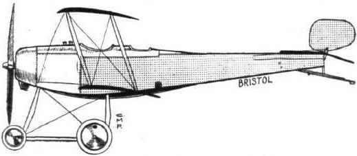
The 80 h.p. Bristol two-seater biplane.

The neat door-catch fitted on the engine inspection door of the Bristol two-seater.
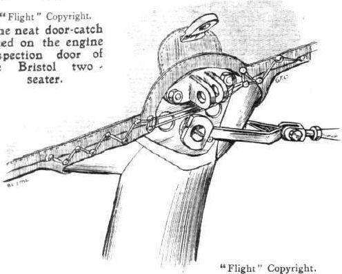
Sketch of the neat steel fitting which joins a chassis strut and a wing spar to the lower longeron of the fuselage of the two-seater Bristol.
Flight, March 14, 1914.
WHAT THERE WILL BE TO SEE AT OLYMPIA.
THE EXHIBITS.
Bristol (British and Colonial Aeroplane Co., Ltd.). (43.)
THIS firm of constructors, who were our sole representative at the recent Paris Aero Exhibition, are showing two machines, one of which is a two-seater with the seats arranged in tandem, and the other a single-seater, as well as their travelling motor-repair workshop. Both machines exhibited are 80 h.p. Gnome-engined tractor biplanes, the engine on the two-seater being of the new Monosoupape type mounted upon supporting plates of pressed steel, and entirely enclosed in an aluminium shield that is continued forward in advance of the propeller for which it forms the boss and with which it rotates.
Special attention has been given in the design of the wings, which, on the single-seater machine, are all fitted with double-acting ailerons. The empennage of this machine is non-lifting, and the frames for this as well as those for the elevator flaps and rudder are of steel tubing, the fabric covering being sewn on. On the two-seater the empennage is set at a negative angle and is used as a directive organ. The landing chassis of the latter is of the standard Bristol type, but the single-seater machine has a special two-wheeled undercarriage. Sufficient petrol may be carried to give a flight lasting for 3 hours in the case of the single-seater and 5 hours for the two-seater.
The travelling workshop is fully equipped with every means necessary for the purpose of executing repairs to an aeroplane, and has been kept to the smallest possible dimensions. Winding gear, for the purpose of enabling the vehicle to wind itself or haul a trailer, is provided, as well as a dynamo of 50 amperes capacity at 65 volts, with suitably arranged switches for controlling the machine tools, which are driven by a separate electric motor. These machines include a lathe, band-saw, drilling machine, portable drill and a grinding machine, but a hand-operated shaping machine is also fitted. Increased floor space n obtained whilst the workshop is at rest, by dropping the two halves of each side door.
Flight, March 21, 1914.
THE OLYMPIA EXHIBITION.
THE EXHIBITS.
BRISTOL. (BRITISH AND COLONIAL AEROPLANE CO., LTD.)
THE two biplanes exhibited on this stand differ considerably from previous models, the two-seater bearing hardly any resemblance to its prototype shown at Olympia last year, whilst the small fast single-seater scouting machine may be said to be the first of a new type to be turned out by this firm.
<...>
In the 80 h.p. Scouting Machine both the span and the chassis appear to have been reduced to a minimum, for the span is only 22 ft. and the chassis is of the simplest imaginable form, consisting of two pairs of V struts of spruce, from which the axle is slung by means of rubber shock-absorbers. The rather wide and deep fuselage is built up in the usual way, and entirely covered in by aluminium in front and fabric in the rear. An 80 h.p. Gnome is mounted on overhung bearings, and almost entirely covered in by an aluminium shield.
The main planes, similar in section, although on a reduced scale, to those of the two-seater, are separated by one pair of struts only on each side, and are attached to the fuselage by means of a steel clip and vertical bolt through the spars. The pilot is accommodated on an aluminium seat of the bucket type, and controls the machine by means of a single central column and a foot-bar. The column terminates in a double handle similar to those fitted on the Prier-type Bristol monoplanes.
The tail planes consist of a flat non-lifting fixed tail plane mounted on top of the fuselage, and of a divided elevator. The rudder is of the balanced type, and no vertical tail fin is fitted. A small pivoted tail skid, sprung by means of rubber shock absorbers inside the fuselage, protects the tail planes.
Flight, April 25, 1914.
THE 80 H.P. BRISTOL "SCOUT."
IT is a matter of gratification that the best of British-built machines are now generally acknowledged to be at least equal to those produced in other countries, in spite of the scant encouragement which the British industry has received in the past. It appears that Great Britain is in a fair way to take the leadership, at least as regards a certain type of machine originated in this country, a type possessing great possibilities, which has not up to the present received much attention abroad. We refer to the small, fast, single-seater, tractor-type biplane. In France, when high speeds are desired, designers almost invariably turn to the monoplane type of machine, whilst German constructors do not appear to pay any considerable attention to really fast machines. There is little doubt, however, that the small span tractor biplane has great possibilities where, in addition to a very high maximum speed, a low minimum speed is desired, for the biplane construction allows of a considerable amount of saving in weight, whilst still retaining a reasonably high factor of safety. Evidently British constructors are realising the possibilities of this type, as, at the recent Olympia Show, three well-known English firms exhibited machines of this type. Of these machines, the one exhibited by the British and Colonial Aeroplane Co. has already proved its capabilities in actual flight. Since the closing of the Show, Mr. Harry Busteed, the well-known Bristol pilot, has done a considerable amount of flying on the machine, most notable among these flights being one made during Easter, when he flew from Salisbury Plain to Brooklands in 27 mins. Of course this flight was accomplished with the aid of a following wind, but even so it was no mean performance.
In the general disposition of its component parts the machine follows standard practice, having a rectangular type fuselage, built up of four longerons, which are of ash in the front portion, and spruce at the rear. Vertical and transverse spruce struts separate the longerons, and the whole structure is made rigid by high-tension steel piano wires attached to steel plate joints. Mounted on overhung bearings in the nose of the fuselage is the 80 h.p. Gnome engine which drives directly a Bristol propeller of 8 ft. diameter. An aluminium cowl almost entirely encloses the engine. This cowl appears to present a comparatively large vertical surface, and it would seem that some form of hemispherical nose-piece, revolving with the propeller as in the large two-seater Bristol biplane exhibited at the Show, might add slightly to the speed. The front part of the fuselage up to a point behind the pilot's seat is entirely closed in by an aluminium covering, whilst the rear portion is covered with fabric. Just behind the inner pair of rear struts is the pilot's cockpit, in which is accommodated the seat, slung from the fuselage on piano wires. By means of the wire strainers incorporated in the seat suspension, the position of the seat may be altered to suit the pilot. Control is by means lever, which operates the elevator pivoted foot-bar actuating the rudder. The vertical lever terminates in a form of handle similar to those known from the Prier type Bristol monoplanes, on which is mounted the switch. Between the pilot's seat and the engine are mounted the tanks, which have a capacity sufficient for a flight of three hours' duration.
Attached to the upper longeron at the rear end of the fuselage, is a flat, non-lifting stabilising plane, to the trailing edge of which is hinged the divided elevator. The rudder is pivoted round an extension of the sternpost of the fuselage, and is partly balanced by a small portion of it projecting forward from the rudderpost above the stabilising plane. All control cables are in duplicate and have a very high factor of safety.
The main planes are chiefly remarkable on account of their unusually short span, and on closer inspection the wing section proves to be highly interesting, as it does not resemble any of the standard sections employed by other well-known firms. As a matter of fact, the section is the same, of course to a reduced scale, as that on the two-seater Bristol machines, which has been found by the Eiffel laboratory to give an exceedingly good lift/drift ratio. This wing section was, as our readers are no doubt aware, designed by Mr. Coanda, and is probably one of the contributory causes to the high speed and good speed range of the machine. Double acting ailerons are fitted to both upper and lower planes, so that the machine must have ample lateral control. Internally the wings are braced by piano wire, whilst the external diagonal bracing is effected by stranded cables having a high factor of safety. Only a single pair of spruce struts on each side of the fuselage separate the main planes, so that there is very little head resistance.
The chassis has been reduced to an absolute minimum. Two pairs of V struts joined at their lower extremities by a transverse member constitute the rigid portion of the chassis. The tubular axle rests in the angle between the struts, from which it is sprung by means of rubber cord. The tail planes are protected against contact with the ground by means of a short skid projecting through the fuselage covering, and sprung inside the fuselage by means of rubber cord. The main characteristics of the machine are :-
Weight of machine empty 616 lbs.
Minimum speed 47 m.p.h.
Useful load carried 340 lbs.
Range of flight 3 hours.
Maximum speed 95 m.p.h.
Flight, May 22, 1914.
THE AERIAL DERBY.
THE PILOTS AND HOW TO RECOGNISE THE MACHINES.
No. 18. The 80 h.p. Bristol Biplane,
as has already been explained, will look, when flying at a height, somewhat similar to the Vickers biplane, but may be identified by its narrower fuselage.
THE MACHINES AND HOW TO RECOGNISE THEM.
No. 18. The 80 h.p. Bristol Biplane is similar to the machine exhibited at the last Olympia Aero Show, on which some time ago Mr. Busteed flew from Salisbury Plain to Brooklands in 27 mins., and as this new machine is, if anything, faster than the old one, it should stand an excellent chance of being one of the first to finish the course.
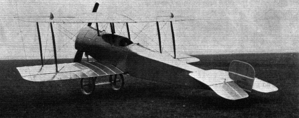
Three-quarter rear view of the Bristol "Scout" single-seater.
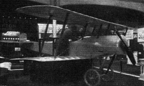
The Bristol scout.
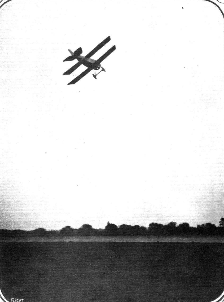
Mr. S. V. Sippe on the Bristol Scout at Brooklands Aerodrome.
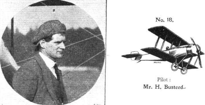
Pilot: Mr. H. Busteed.
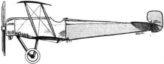
The small 80 h.p. Bristol single-seater.
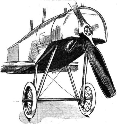
Chassis and engine housing on Bristol "Scout."

The tail of the Bristol "Scout" biplane.

Attachment of tail plane on Bristol "Scout."

Wing section of the Bristol "Scout."
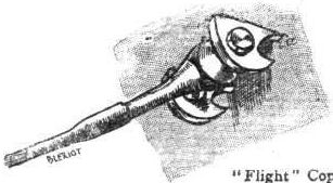
Attachment of lift cable.
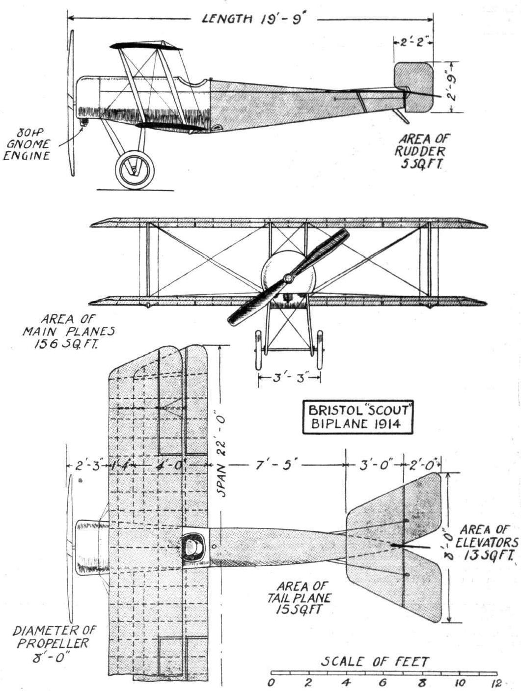
THE BRISTOL "SCOUT" BIPLANE. - Plan, front and side elevation to scale.
Flight, January 24, 1914.
The Collins-Hancock Monoplane.
THIS machine was designed especially as a military scout.
It can be easily dissembled for road transport, the wings folding against the front skids, thus making the overall dimensions 20 ft. by 7 ft.
If necessary, the fuselage and nacelle, which are built up together, can be detached and fitted nacelle first in between the front skids, the tail plane and elevator being hung under the front elevator, thus reducing the length to approximately 15 ft.
The only controls which would need attention are the front elevator and ailerons.
The ailerons are controlled by rods and links, being absolutely rigid.
Referring to the drawing, the ailerons are hinged on to rods, B and B1, which are fixed inside the planes, so that they can revolve freely. These rods have links, A and A1, attached at their inside ends, which are connected to a rocking bar inside the nacelle, which rocks up or down according to the movement of the control lever.
When the rocking bar is working, it pushes link A up and pulls link A1 down, or vice versa, thus revolving the rods B and Bl in opposite directions, so that one aileron attains a positive and the other a negative angle of incidence.
The propeller revolves on the top member of the triangular fuselage, and is driven by bevel gears.
The twin rudders are connected together by a rod, the control wires being taken from the ends of the rod.
The pilot has a clear view below.
It is essentially a speed machine, and will land at high speeds, but the landing chassis is one which has been proved satisfactory for large and heavy machines, so should be amply strong for this machine.
#A.L.C.
Flight, January 3, 1914.
THE PARIS AERO SALON - 1913.
NIEUPORT.
<...>
The Nieuport-built Dunne biplane completes this exhibit, but as the Dunne machine has been fully described quite recently in the columns of FLIGHT, there is no need to describe it here in detail. Several minor alterations have been made in the construction, for instance, the nacelle is built up of steel tubes, and is of a slightly different form from that of the British-built machine. Also the chassis has been altered, and is in this machine surprisingly like the chassis fitted on the Bleriot biplane. Another alteration is that all the inter-plane struts are made of streamlined steel tubes, whereas in the British machine, it will be remembered, they were made of spruce. The workmanship of this machine, as well as that of all the monoplanes, is of very high quality, as one might expect from a firm of Nieuport's standing.
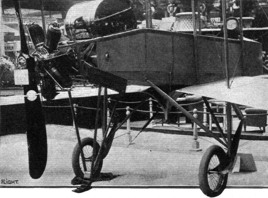
Chassis and nacelle of the Nieuport-built Dunne biplane.
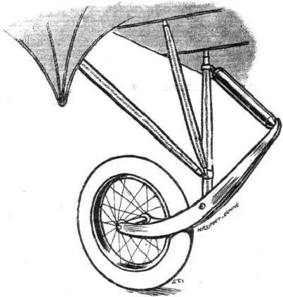
Sketch illustrating the method of springing employed on the Nieuport-built Dunne biplane.
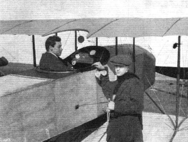
Mr. R. E. B. Hunt in the pilot's seat of his 50 h.p. Gnome tractor biplane, designed by Mr. E. L. Gassier (standing by the machine) and built by the Eastbourne Aviation Co., Ltd.
Flight, September 4, 1914.
THE "ROUND BRITAIN" MACHINES.
THE machine officially numbered 5 in the Circuit of Britain, and which was to have been piloted by Mr. F. B. Fowler, was
The E.A.C. Tractor Seaplane.
This machine differs as a type from any of the other machines entered, in that it is a twin-tractor, fuselage biplane, although having its engine at the rear of the pilot. Constructionally the fuselage does not differ materially from usual practice, being built up of four ash longerons connected by struts and cross members of spruce, the whole braced with steel wire in the usual way. In shape, however, the fuselage deviates from standard types in that the longerons are swept upwards towards the rear in order to provide sufficient water clearance and thus dispense with the necessity of a tail float. In place of the latter member a safety tank is fitted inside the last bay of the fuselage. A good streamline is given to the fuselage by means of a turtle back and a rounded bottom, whilst the sides have been kept fiat, in order, probably, to provide the necessary vertical surface.
In the nose the fuselage is rounded to form a good entry for the air, and the turtle back is here swept up to form a wind screen in front of the occupants' seats. These are arranged side by side in a very roomy cockpit, and as they are practically on a level with the leading edge of the wings an exceptionally good view is obtained in a forward and downward direction, whilst the absence of any propeller draught, due to the mounting of the two propellers a considerable distance away from the fuselage, renders this machine as comfortable to fly as machines of the usual "pusher" type.
Behind the seats and inside the fuselage is situated the engine - a 100 h.p. Green - which drives the two tractors through two inclined shafts and bevel gears.
A special gear-box is attached to the engine, and the shafts, which are enclosed in torque tubes, run from here to other gearboxes bolted to the two interplane struts that carry the two tractors. Large petrol and oil tanks are provided inside the fuselage, and contain a supply sufficient for a flight of seven hours' duration, or 70 gallons of petrol and 6 gallons of oil.
The wings follow standard practice as regards their construction, and are characterised by having their trailing edge slightly longer than the leading edge, as shown in the accompanying plan view of the machine. The upper main plane is straight, whilst the lower one is set at a dihedral angle of 3° for the double purpose of increasing the lateral stability of the machine in flight, and to give adequate water clearance when on the surface of the sea. Eight pairs of spruce struts separate the main planes, and cable bracing is employed. Large ailerons are fitted to the outer portions of the trailing edge of upper and lower planes. Lateral control is by means of a rotatable hand wheel mounted on a vertical column in front of the pilot. As in practically all modern machines the ailerons are interconnected, so that when one is depressed the other is correspondingly elevated.
The tail planes consist of rudder, stabilizing plane, and elevator, whilst no vertical fixed surface is fitted, probably on account of the fact that the fuselage is comparatively deep at the rear and thus provides the necessary vertical surface. Should it be found desirable to fit vertical fins this may be easily accomplished, as the stern post of the fuselage is extended in both upward and downward directions. The fixed stabilizing plane, which is of roughly semi-circular shape, is attached to the sides of the fuselage, and is approximately in line with the propeller shafts. It is braced by steel tubes to the lower longerons. To the trailing edge is hinged the divided elevator.
The landing chassis consists of two long floats, each of which is carried on two pairs of struts, one pair running to the lower longerons of fuse/age and the other to the two interplane struts that carry the propellers. To add to the lateral rigidity of the whole structure stay wires are taken outwards to the interplane struts and inwards to the fuselage. As the floats are placed so far - 12 ft. - apart, it has been found unnecessary to fit any auxiliary floats to the wing tips. The floats themselves are 19 ft. long with a beam of 2 ft., and have a "Vee" bottom in front running into a flat bottom at the rear.
The weight of the machine empty is 1,850 lbs., and fully loaded 2,800 lbs., giving a loading of 4 lbs. per square foot. A maximum speed of 65 m.p.h. is anticipated, whilst it is hoped to bring the minimum speed down to about 45 m.p.h.
In view of the way in which this machine departs from what might be termed standard practice, its trials will be watched with the greatest interest.
Flight, December 11, 1914.
E.A.C. SEAPLANE FLOATS.
IN FLIGHT for September 4th last, full particulars were published with scale drawings of the Eastbourne Aviation Co.'s Circuit tractor seaplane. This machine, as our readers are aware, embodies several interesting features which, while to some extent to be regarded as innovations, cannot be viewed in any way as experiments, since they are the natural outcome of the experience of its sponsors, Mr. F. B. Fowler and Mr. F. Hucks, and of development.
During a recent visit to the company's works, opportunity was afforded of closely inspecting this seaplane, which is of exceptionally substantial construction.
Special attention has been given in the design to ensure the machine getting off the water even under adverse circumstances. Two factors tend to prevent a machine rising from the water, at all events in a seaway. The first is that as the aeroplane moves over the water, the floats, to some extent, endeavour to follow the natural formation of the surface; with the result that the tail, as it rises and falls, strikes the water and prevents the speed from rising sufficiently to allow the machine to get off. Much can be done to prevent the immersion of the tail by the use of a tail float, or perhaps better still, by using long floats of ample flotation; and it is the latter that are provided on the E.A.C., their length being no less than 19 ft. with a width of 2 ft. But in addition, the body, which is so capacious that three persons can sit comfortably within the cockpit, while another may be stowed at the side of the engine, is upswept to a marked degree, so that it resembles, in some ways, the appearance of a bird. This combination of long floats and upswept tail should enable the machine to be used in comparatively rough seas.
A seaplane is also occasionally prevented from getting away owing to the suction beneath the floats, and a system has therefore been devised to overcome this effect. Each of the floats, which are of particularly strong design, is divided into six compartments by one longitudinal and two athwartship bulkheads. On the under side of the floats are two steps, and the sides of the compartments are continued downwards, as shown in the accompanying sketch, so as to form a skirting, which, quite incidentally, prevents damage to the floats and keeps the machine level when it is standing upon the ground. At the front end of the float, near the upper surface, two pipes are inserted one on each side, which pass through the first athwartship bulkhead and have their other ends open at the commencement of the first step. The ends of these pipes are flanged and rivetted to the body of the float, and a joint is made between the piping and the bulkhead in order to prevent leakage should one compartment be punctured. Thus, as the seaplane travels over the surface of the water, air passes in through these pipes, effectively breaking the partial vacuum formed at the steps which tends to prevent the machine from leaving the surface.
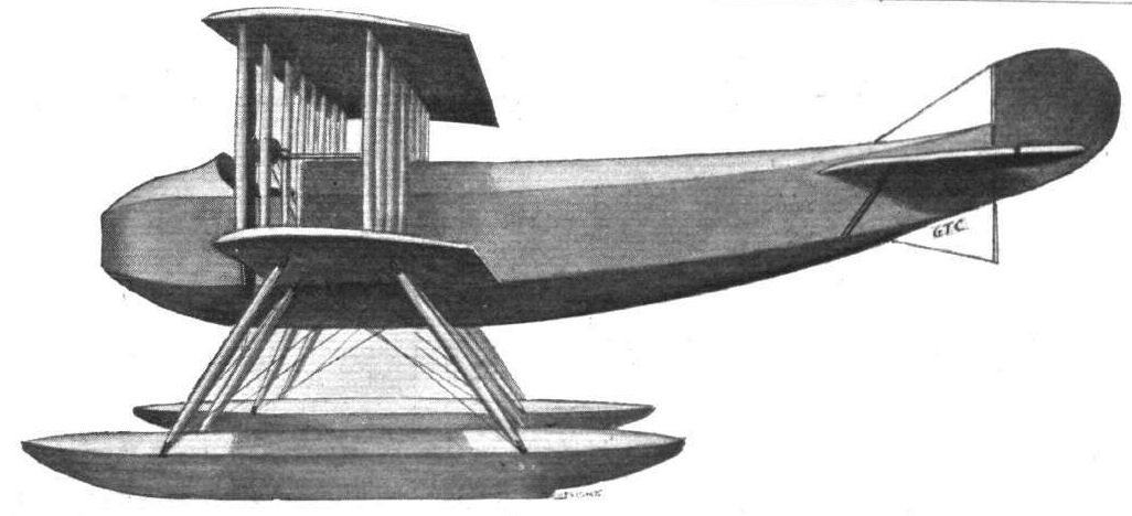
ROUND BRITAIN MACHINES, No. 5. - The E.A.C. biplane.
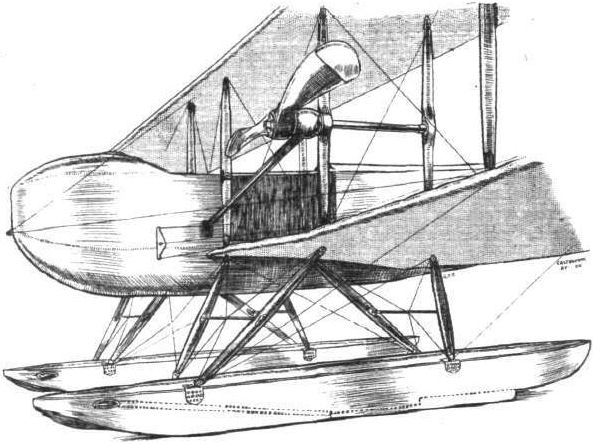
Sketch showing the general arrangement of the alighting gear on the E.A.C. "Circuit" tractor. Note the air tubes bitween the front of the float and the steps.
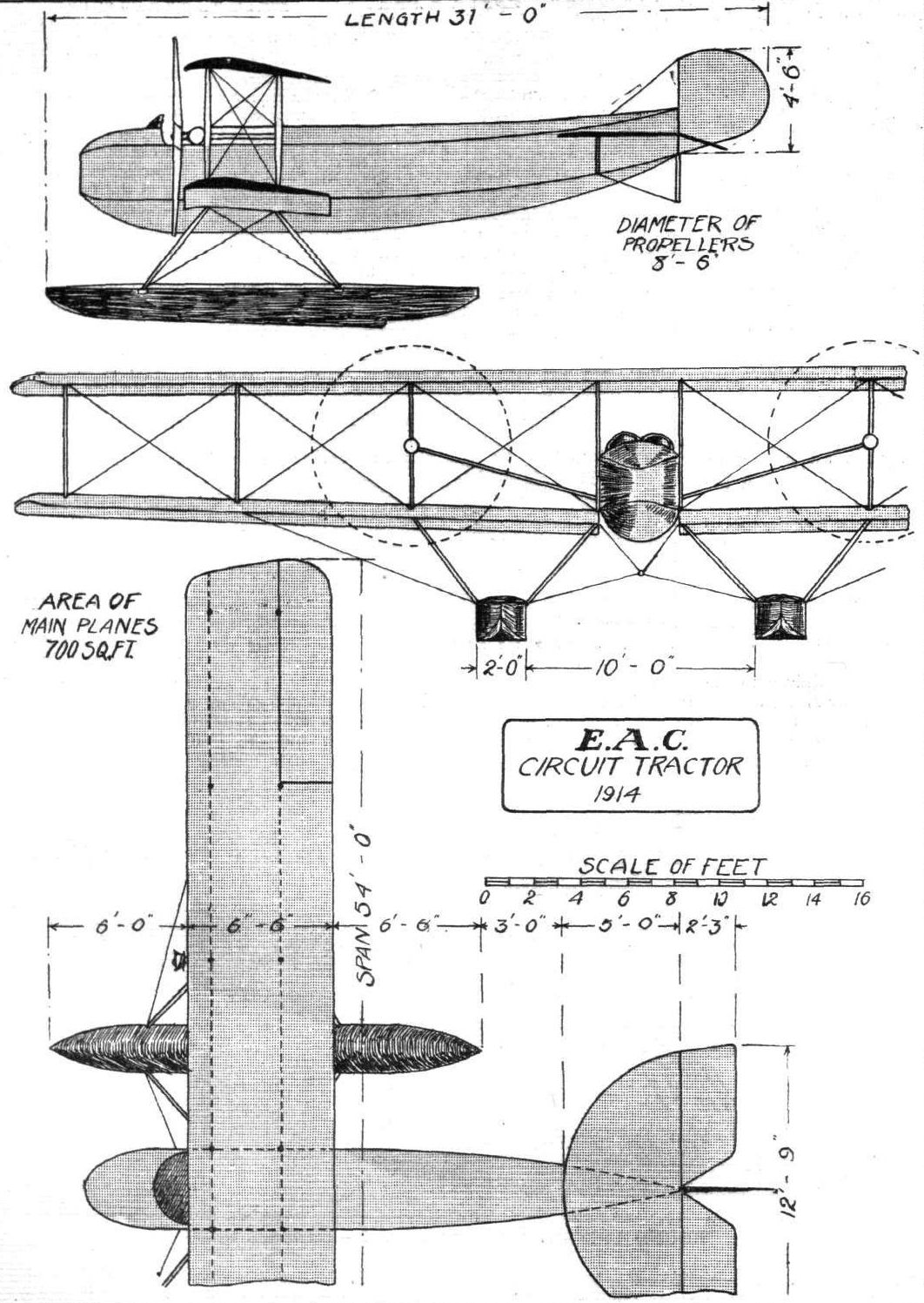
ROUND BRITAIN MACHINES, No. 5. - The E.A.C. biplane. Plan, front and side elevations to scale.
Flight, March 21, 1914.
THE OLYMPIA EXHIBITION.
THE EXHIBITS.
E.A.C. (EASTBOURNE AVIATION CO.). (70.)
ARE showing an 80 h.p. Tractor Biplane, which is chiefly remarkable for the ease with which it can be erected and dismantled. Owing to the non-arrival of the particulars relating to the exhibit on this stand until too late for inclusion in our last issue, we were precluded from furnishing details respecting it. The machine is fitted with an 80 h.p. Gnome engine, mounted on overhung bearings in the nose of the fuselage, and covered in by an aluminium shield. The fuselage, which is entirely covered in, is built up in the usual way and follows standard lines. Inside this fuselage are arranged the pilot's and passenger's seats, tandem fashion, with the pilot in front. Control is by means of a single central lever and a foot bar. The chassis, which is of rather unusual type, consists of streamlined steel tubes, of which the rear ones are curved forward and upwards to form short skids. The tubular axle, which rests in slots in the V between the tubes, is sprung by rubber shock absorbers, and carries the two wheels, which are fitted with large size Palmer tyres.
The main planes, of which the trailing edge is slightly longer than the leading edge, are separated by four pairs of poplar struts, in addition to two pairs of steel tube streamlined struts running from the centres of the front and rear spars, and sloping down to the fuselage to a point on the upper longerons immediately above the point of attachment of the chassis struts to the lower longerons. Cross bracing of the wings is effected by means of stout stranded cables, each of which is fitted with the combined quick release device and wire strainer shown in the accompanying sketch. It is only a few minutes' work to undo these quick releases and the bolts which secure the spars to the fuselage, and the wings can then be folded flat for packing or transport. The tail planes are so mounted on the fuselage that they can, by undoing a few bolts, be folded down flat along the sides of the fuselage, and thus take up very little room. In order to provide the pilot and passenger with a better view of the ground below, the wings have been left uncovered near the fuselage, and the portion of the spars which is thus left uncovered is enclosed in a streamlined casing. The main characteristics of this machine are :-
Span of upper plane 36 ft.
,, lower " 30 ft.
Length 24 ft.
Weight 950 lbs. empty
Speed 50-75 m.p.h.
Flight, April 18, 1914.
THE E.A.C. TRACTOR BIPLANE.
ALTHOUGH the biplane with which the Eastbourne Aviation Co. made their debut at the recent Olympia Aero Show does not differ radically, as a type, from already existing machines, there is ample evidence of the careful attention which the designer, Mr. E. L. Gassier, has paid to constructional details. Designed primarily to comply with military requirements, such features as would be desirable in a military machine have been closely studied, and every effort has been made to produce a machine which, whilst being sufficiently strong to stand reasonably rough usage, is still light enough to provide a good climbing capacity. Another feature which should be a point in its favour, is the ease with which the machine may be erected and dismantled for storage and transport, operations occupying, we understand, only a few minutes.
The rectangular section fuselage is of the usual girder type, built up of ash longerons connected by struts and cross members, of which the front ones are steel tubes, whilst the rear ones are spruce. The fuselage is rather longer in proportion to the span than one usually finds on machines of this type, thus providing a good leverage for the tail planes. Mounted on overhung bearings in the nose of the fuselage is the engine, an 80 h.p. Gnome, which is partly enclosed by an aluminium cowl for the protection of the pilot and passenger against oil spray. Inside the fuselage and between the engine and pilot's seat are the oil and petrol service tanks. Petrol is forced to this service tank from the main tank carried behind the pilot's seat by means of a hand operated petrol pump. The pilot's and passenger's seats are arranged tandem fashion, the pilot occupying the front seat. From the passenger's or observer's seat an excellent view is obtained, this being further enhanced by leaving the inner portion of the lower main planes uncovered where they join the fuselage. In order to reduce head resistance on the thus uncovered spars, these have been enclosed in streamlined casings, as shown in one of the accompanying sketches, which also shows the method of attaching the spars of the lower plane to the fuselage. Ailerons and elevator are operated by a single central column in front of the pilot, whilst the rudder is actuated by a pivoted foot-bar. The instruments carried are the usual for cross-country work, such as altimeter, compass, clock, revolution indicator and air-speed indicator. A starting handle in front of the pilot makes it possible to start the engine without the necessity of any preliminary swinging of the propeller, a point which should be especially valuable for cross-country flying, as it enables the pilot to make a start without any outside assistance, which is not always available when making forced landings during a prolonged cross-country flight.
As will be seen from the accompanying scale drawings, the trailing edge of the planes is slightly longer than the leading edge, and the upper main plane has a slight overhang. The wings are built up over two ash spars of approximately rectangular section, to which are secured the ribs. These are built up of poplar flanges on three-ply webs. The leading and trailing edges of the wings are formed by spruce stringers. It will be noticed that in the outer portion of the wing the leading edge slopes backwards towards the front spar, but in later machines this feature will be discarded as making the wings more expensive to build and being of no particular aerodynamical value. The main planes are separated by four pairs of poplar struts, two pairs each side, whilst a cabane-like structure mounted on the upper longerons of the fuselage takes the place of the usual four upright struts in the central cellule. Cross bracing is effected by means of stranded cables terminating in the quickly detachable devices illustrated in one of the accompanying sketches. By undoing these combined quick releases and turn buckles, the wings can be dismantled in a very short space of time. The angle of incidence is 4 1/2 degrees, and there is no dihedral angle. Ailerons are fitted to the top plane only.
The chassis is of a very simple type, consisting of two Vs of streamline steel tubes extended forward to form short tusks or skids. The axle rests in slots in flange pieces in the angle between the struts, and is sprung by means of rubber cord. Palmer cord tyres of large size are used, and the wheels are enclosed in fabric covers, in order to reduce the head resistance.
The tail planes consist of a flat triangular stabilizing plane hinged to the upper longerons of the fuselage. The divided elevator is hinged to the trailing edge of this fixed tail plane, and by undoing a few nuts both stabilizing plane and elevator can be folded down flat along the body, thus taking up very little room. A small triangular vertical fin is fitted in order to counteract the forward side area of the fuselage, and to the trailing edge of this fin is hinged the rudder. A tail skid of the type shown in one of the accompanying sketches protects the tail planes against contact with the ground. The weight of the machine empty is 950 lbs., and her speed is expected to be from 50 to 75 miles per hour.
As soon as the machine is completed by the Eastbourne Aviation Company, she will be put through her tests, and there seems little doubt but that she will give a good account of herself, for Mr. Gassier is not only a designer of considerable experience but is also a very capable pilot.
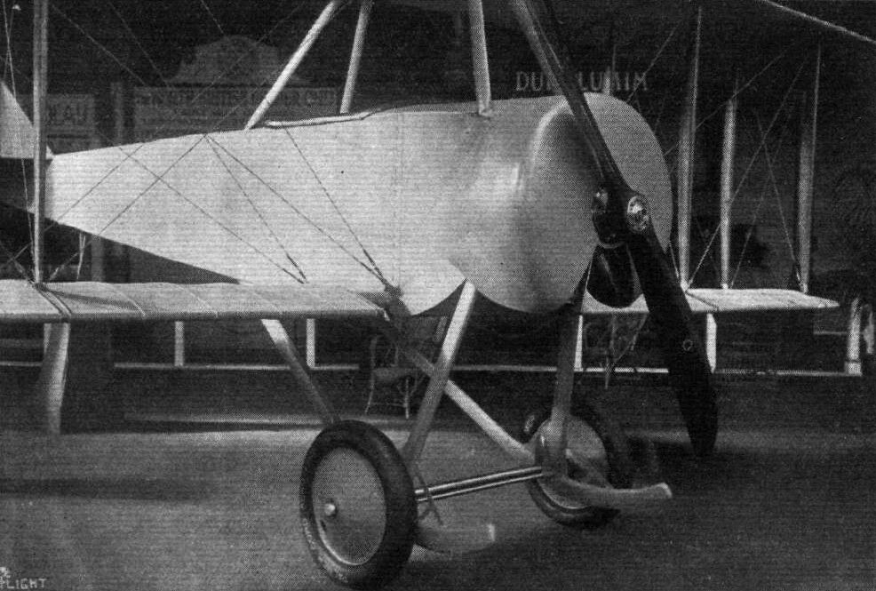
Nose and fuselage of the Eastbourne Aviation Co.'s 80 h.p. tractor machine.
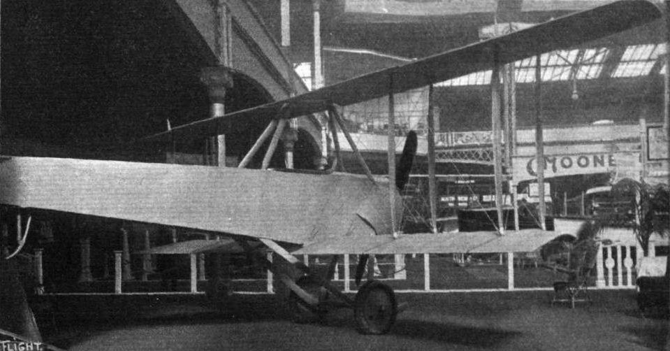
A three-quarter rear view of the 80 h.p. tractor machine exhibited on the Eastbourne Aviation Co.'s stand.

Tail planes and rudder of the Eastbourne Aviation Co.'s 80 h.p. tractor biplane.
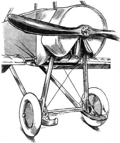
Chassis and engine housing of the E.A.C. biplane.

View from underneath of E.A.C. tail planes.
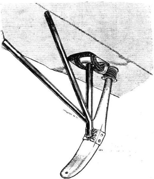
The E.A.C. tail skid.

Attachment of plane strut and quick release devices on the E.A.C. biplane.
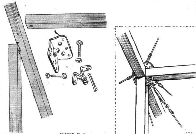
Method of mounting upper main plane on E.A.C. cabane.
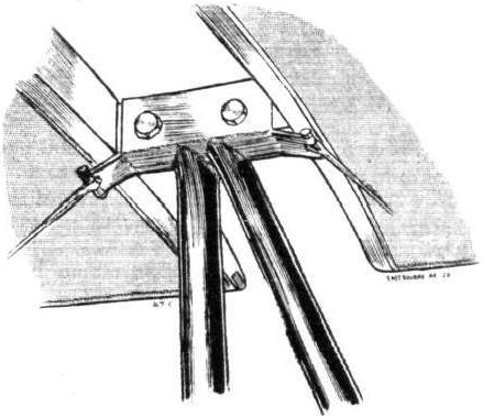
A neat way of joining struts and cross members to fuselage longeron of the E.A.C
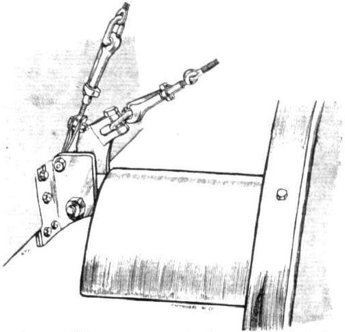
Attachment of lower spar to fuselage of E.A.C. biplane. Note streamline casing round spar where wing has been left uncovered.
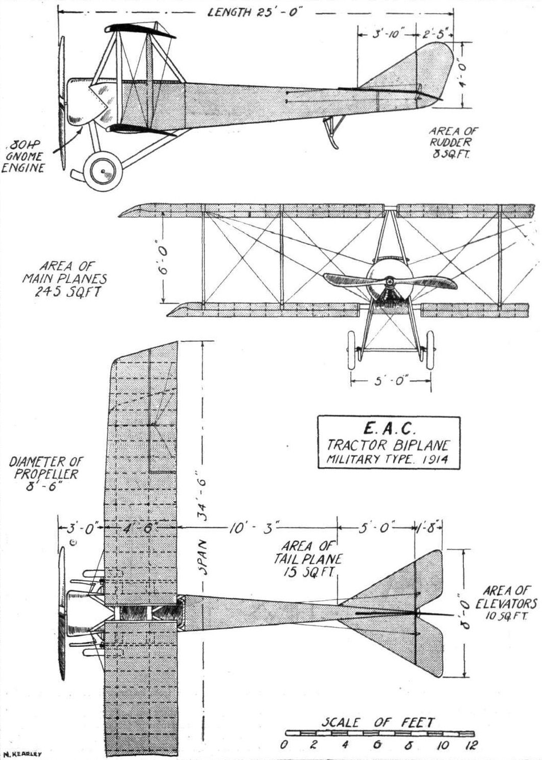
THE E.A.C. BIPLANE. - Plan, side and front elevation to scale.
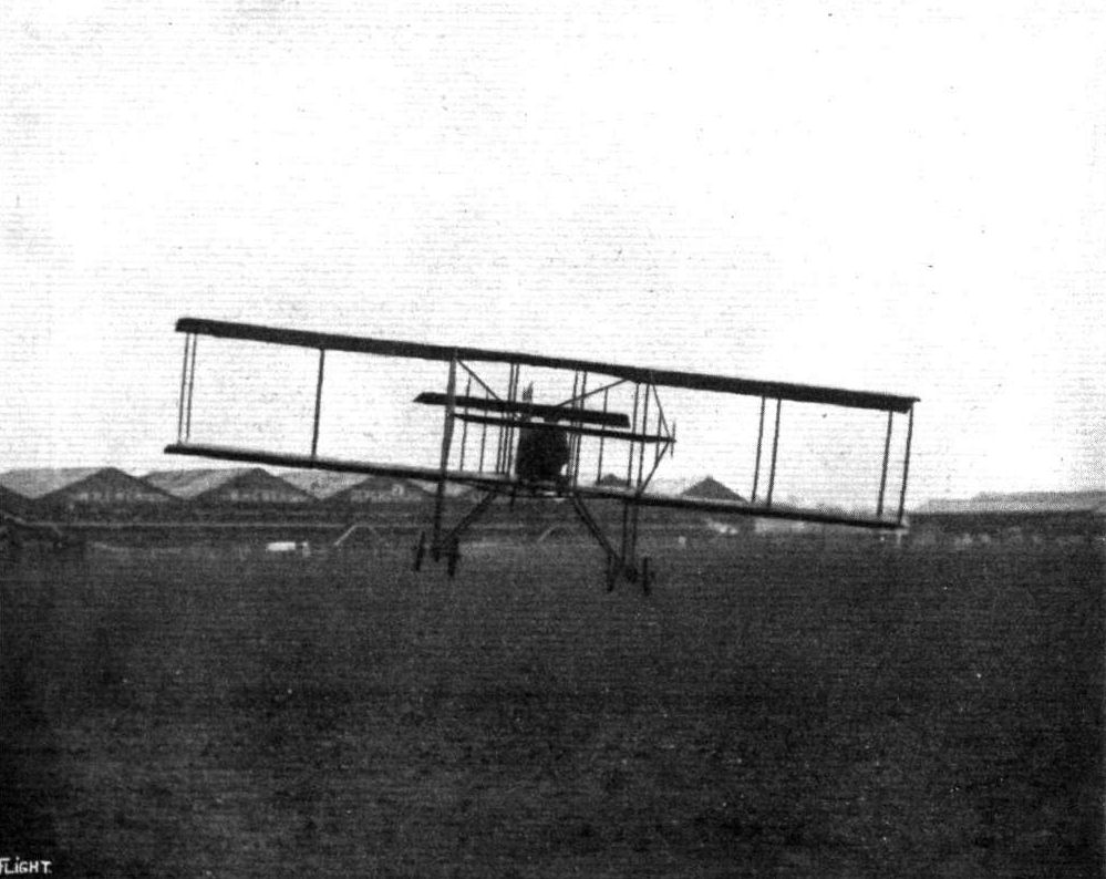
A NEAR THING FOR OUR PHOTOGRAPHER. - A direct snap from in front of Mr. Reginald Carr on the G.-W. biplane at Hendon Aerodrome.

Louis Noel on the Bleriot overtaking Louis Strange flying the Grahame-White Boxkite during a race at Hendon on 14 March, 1914.
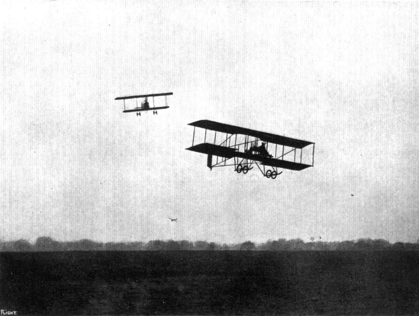
RACING AT HENDON. - A G.-W. 'bus, and on the left "Lizzie."
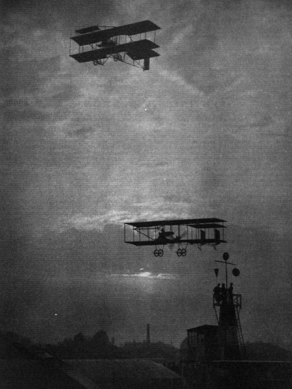
AS EVENING DRAWS IN AT HENDON AERODROME. - Above, Mr. H. P. Carr, and below, Mr. M. D. Manton on Grahame-Whlte biplanes rounding one of the pylons.

An exquisite specimen of the silversmith's art, being a scale model in silver of the Grahame-White biplane used by Mr. Birchenough, the winner of the trophy. This trophy was presented by the distributors of Shell Motor Spirit for a special speed contest. The model is the work of Messrs. Mappin and Webb, Ltd., of Oxford Street.
Flight, March 7, 1914.
THE GRAHAME-WHITE TRACTOR BIPLANE,
IT is the usual practice of manufacturers who have evolved a successful machine to retain the main design and confine their attention in future machines to detail improvements. Not so with the Grahame-White Aviation Co. Since this enterprising firm first entered the field of aeroplane construction, they have turned out one type of machine after another, each of which has had hardly any resemblance to its predecessor. A pusher box kite was followed by a tractor biplane, then a monoplane; Next in turn was another pusher, this time quite a small affair, only to be succeeded by a huge biplane which, on account of its weight-carrying capabilities, was dubbed "Char-a-bancs." The next machine to issue from the G.-W. works was a diminutive biplane of the tractor type, and this had scarcely left the stocks before another and different type was put in hand for the Olympia show. But we are anticipating events.
The subject of our scale drawings this week issued a the Grahame-White works some time ago, and created some excitement by winning a cross-country race the first time she was flown, without any previous test flights of any description. Since then this machine has been flown repeatedly at Hendon, where she is known to frequenters of the aerodrome as "Lizzie." However, in spite of her rather startling appearance she flies quite well in the hands of Mr. Reginald Carr.
As will be seen from the accompanying scale drawings the upper plane possesses a very considerable overhang, the lower plane being of quite diminutive size. As the fuselage is placed comparatively low down - right on top of the lower plane in fact - the centre of gravity, as well as the centre of thrust, must be considerably lower than is usual in machines of this type. From a rough estimate of weights and resistances, it would be expected that the machine would be very sensitive to variations in thrust, such as are caused by switching the engine on and off, but a careful inspection of the machine in flight failed to show any such tendency, so that one can only assume that the horizontal area of the enclosed fuselage acts as a very effective damper plane in preventing any sudden oscillations around the transverse axis of the machine. Also transversely the machine appears to be very stable, the large ailerons fitted to the upper plane rarely being called into action, and on such occasions as they are used they seem very effective, so that the machine appears to be amply controlled.
As for the low centres of gravity and thrust, these cannot be lower than those of the Morane-Saulnier "Parasol," which is, perhaps, the machine with which this new Grahame-White tractor may be most readily compared, and which has already shown itself capable of very good performances, indicating that in a modern machine a low centre of gravity is not necessarily detrimental to good flying qualities.
Constructionally the machine is built along orthodox lines following standard practice. The fuselage, which, it will be seen, is similar to that of the Morane-Saulnier monoplane, is built up of four longerons connected by struts and cross members, the whole being made rigid by diagonal cross bracing in the usual way. The longerons converge to a horizontal knife's edge at the rear, where are carried the tail planes, which are similar in shape although differing in size from those on the Moranes. No fixed tail plane is fitted, the enclosed fuselage performing the function, as has already been said, of the damper plane. In the front portion of the fuselage is arranged the pilot's seat, in front of which is the control lever, a universal pivoted steel tube actuating the elevator and ailerons in the usual way. A pivoted foot-bar operates the rudder. The pilot is protected against the wind by a neat little shield of transparent material. Mounted on overhung bearings in the front of the fuselage is the engine - a 50 h.p. Gnome - which drives directly a propeller of 7 ft. 6 ins. diameter. Between the engine and the pilot's seat are the oil tanks, and a service petrol tank containing 12 gallons, whilst an additional supply of 10 gallons of petrol is carried in a reserve tank behind the pilot's seat. The fuselage is covered with fabric in the rear portion, whilst the front part is covered with three-ply wood. The main planes, of which the upper one has a very pronounced overhang, are built up over two main ash spars, both of I section, and the ribs occur at every foot, approximately, along their length. At those points at which the interplane struts are attached to the spars, the ribs are of the hollow box variety; in other places they are built up, I section, of spruce flanges and three-ply webs. To better maintain the shape of the plane, false ribs, extending from the loading edge to the front spar, are arranged halfway between each pair of main ribs, and a pair of transverse stringers are run, at a point halfway between the front and rear spars, from one end of the plane to the other. Four pairs of spruce struts connect the main planes by diagonal cross wiring. The chassis, which is of the Henry Farman type, consists of two ash skids, carried on vertical struts of the same material, and made rigid by means of steel tubes of streamline section, which slope inwards to join the lower main spars at the point where the latter join the interplane struts. Each skid carries a pair of wheels on a short tubular axle, sprung from the skid by rubber shock absorbers. In order to lighten them, the skids are spindled out to an I section between the points where the struts are attached. Two tubular cabanes or king posts serve as an anchorage for the upper bracing wires, which carry the weight of the extensions of the upper plane, when the machine is on the ground. A tail skid, similar to the one employed on the Morane-Saulnier monoplane, protects the tail planes against contact with the ground. The machine gets off very quickly, and appears to climb well, and she is certainly very fast for a biplane with so small power. Her speed is in the neighbourhood of 65 m.p.h., and the weight is 850 lbs., including pilot, petrol, and oil.
Flight, May 22, 1914.
THE AERIAL DERBY.
THE PILOTS AND HOW TO RECOGNISE THE MACHINES.
No. 2. The 50 h.p. Grahame-White Tractor Biplane
may be recognised by the comparatively great gap between the main planes, and also by the small size of the tail planes. The fuselage is similar to that of the Morane monoplane.
THE MACHINES AND HOW TO RECOGNISE THEM.
No. 2. The 50 h.p. Grahame-White Biplane is the machine which is familiar to our readers under the pet name "Lizzie." It is on this machine that Mr. R. H. Carr has for the past few weeks been giving such successful demonstrations of looping the loop.
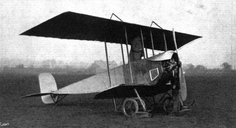
The Grahame-White Lizzie - a popular winner of races at Hendon during 1913.
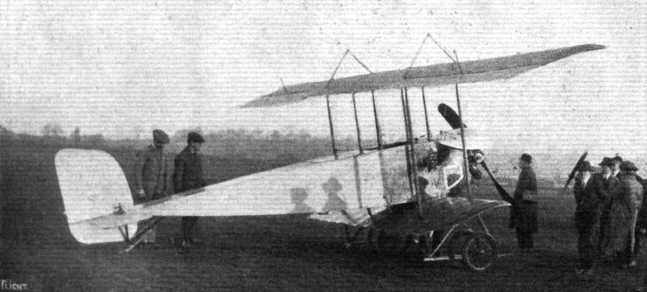
Three-quarter rear view of the Grahame-White tractor biplane.
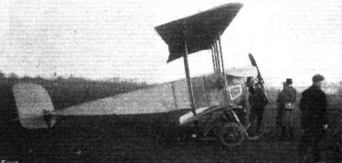
The Grahame-White Tractor Biplane (No. 2).
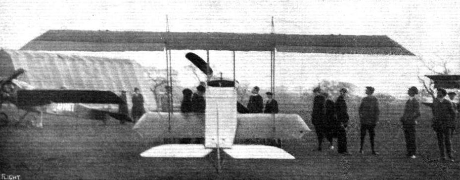
The Grahame-White tractor biplane as seen from behind.
RACING AT HENDON. - A G.-W. 'bus, and on the left "Lizzie."
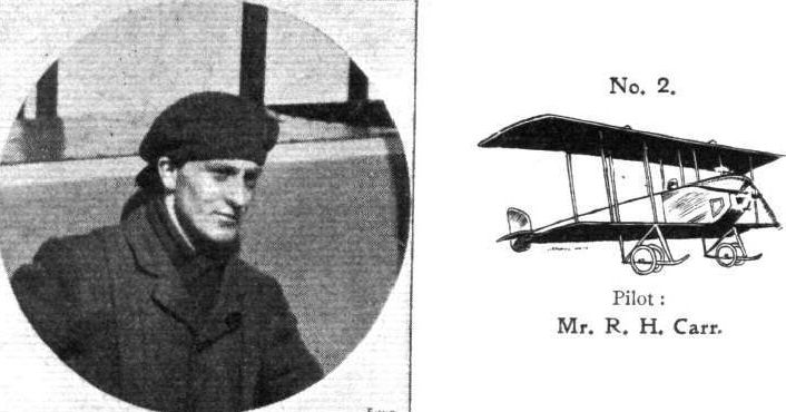
Pilot: Mr. R. H. Carr.

Sketch of pilot's cockpit in the Grahame'White tractor biplane.

Strut socket and pulley for aileron cable, method of joining struts and cross-members to fuselage longeron, and tail plane of the Grahame-White tractor biplane.
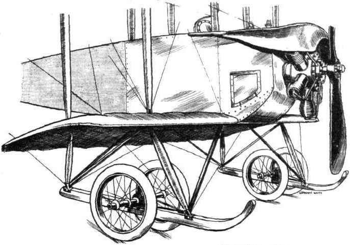
Chassis and engine mounting of the Grahame-White tractor biplane.
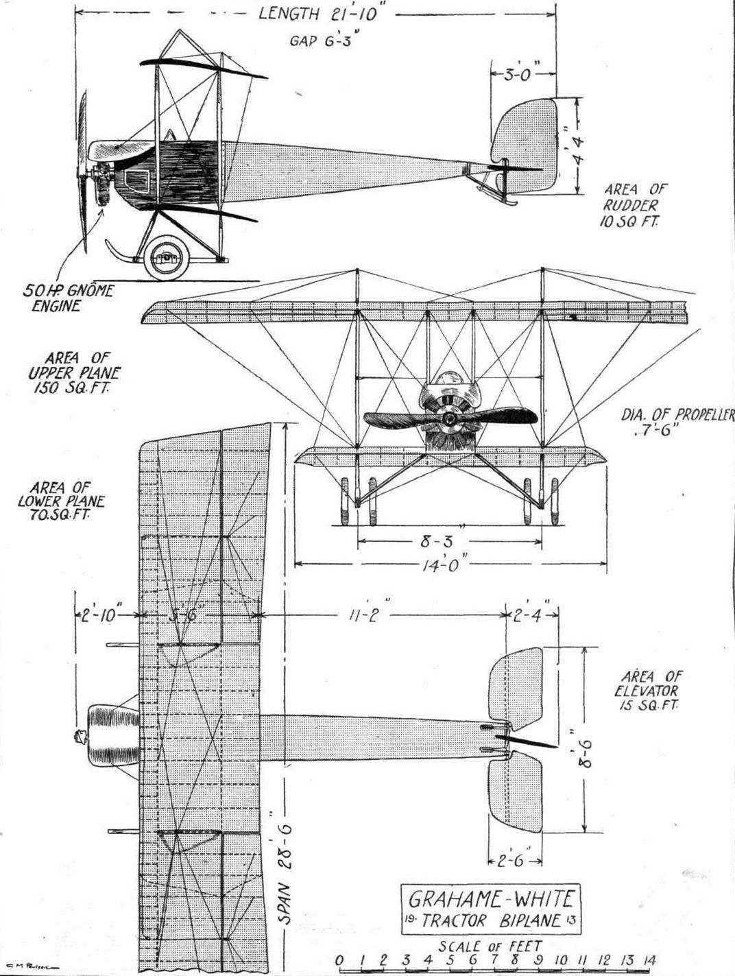
THE GRAHAME-WHITE TRACTOR BIPLANE. - Plan, side and front elevation to scale.
Flight, July 31, 1914.
EDDIES.
The ever-growing list of "professionals" who have made the jump from the slanting boards to the pilot's seat has received a new addition in Mr. Chas. Weber, of Budapest, who has taken his "ticket" recently at the Grahame-White School at Hendon. Mr. Weber, who is an acrobat by profession, and who has appeared on many of the London halls, has done a considerable amount of flying on various machines in Hungary during the last two years, and has had several rather exciting experiences. On one occasion when Mr. Weber was flying for his ticket on a monoplane fitted with an experimental engine, and was doing some very artistic figures of eight, the engine and the machine dissolved partnership. The return to earth was nothing like as graceful as had been the figures of eight; in fact, it was very decidedly a case of "boys cassy." Fortunately Mr. Weber was not seriously hurt, but his judgment got the better of his patriotism, and he decided to journey to this country to learn flying on a real aeroplane.
"AEOLUS."
AS EVENING DRAWS IN AT HENDON AERODROME. - Above, Mr. H. P. Carr, and below, Mr. M. D. Manton on Grahame-Whlte biplanes rounding one of the pylons.

FLYING AT HENDON. - Mr. Grahame-White on an M. Farman and Mr. Lillywine on the twin-rudder G.-W. 'bus over No. 1 pylon.
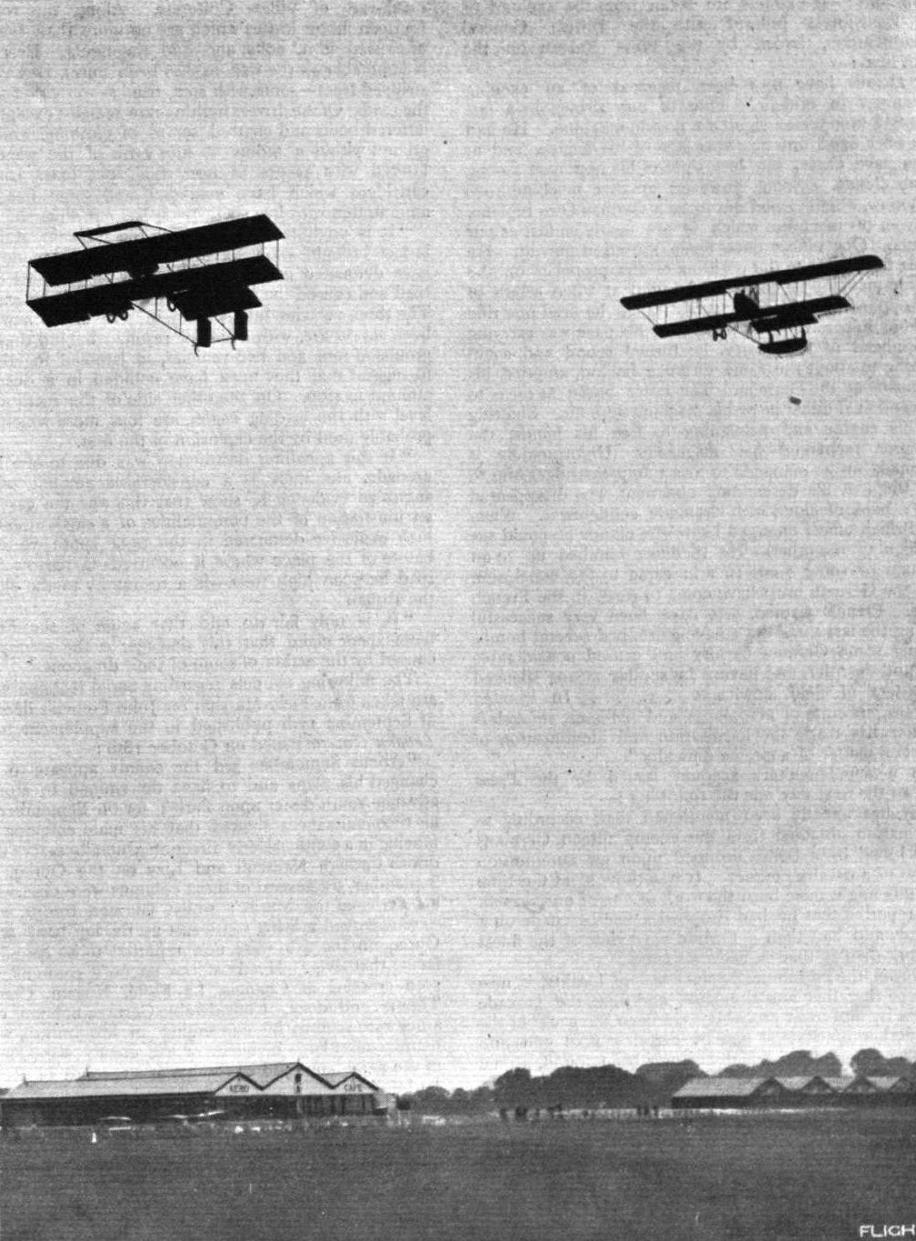
CLOSE FINISHING AT HENDON DURING THE SUMMER RACING SEASON. - Mr. Lillywhite on the Grahame-White biplane and Mr. Birchenough on a Maurice Farman.
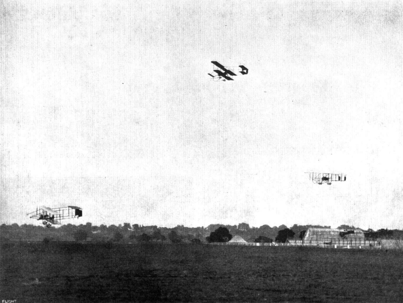
RACING AT HENDON. - The second heat of the Speed Handicap on Whit Saturday. From left to right the machines are: Messrs. R. J. Lillywhite (G.-W. twin rudder), Verrier (Maurice Farman), W. Birchenough (G.-W.-Maurice Farman), and L. Noel (Bleriot).
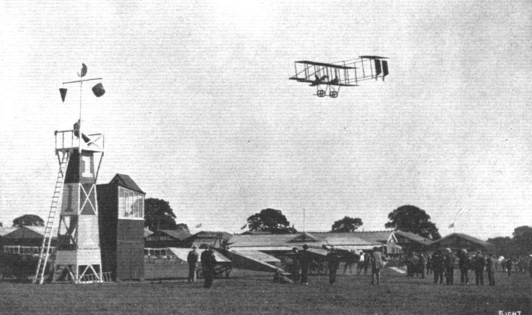
R. J. Lillywhlte, on the.bi-rudder G.-W. 'bus, completing his first lap and passing over two machines still waiting to start in the Cross-Country Handicap at Hendon on Saturday.
Chas. Weber, the Hungarian pilot who has taken his brevet at the Grahame-White School recently.
Flight, March 14, 1914.
WHAT THERE WILL BE TO SEE AT OLYMPIA.
THE EXHIBITS.
Grahame-White (Grahame-White Aviation Co.). (40.)
ON the stand of the Grahame-White Avation Co., Ltd., will be shown two biplanes, one of which is already known to our readers through descriptions in the columns of FLIGHT, i.e., the five-seater biplane which established a record by carrying ten passengers at Hendon. This machine will be all-British, as it will be fitted with a 100 h.p. Green engine.
<...>
Flight, March 28, 1914.
THE OLYMPIA EXHIBITION.
THE EXHIBITS.
GRAHAME-WHITE. (GRAHAME-WHITE AVIATION CO., LTD.)
ON this stand were shown a complete two-seater biplane and the central portion of the Grahame-White five-seater biplane which established a record at Hendon by carrying ten passengers. A third machine, the Morane "Parasol," did not arrive in time for the Show. The 100 h.p. Grahame-White Five-Seater is already known to our readers through a very detailed description in the columns of FLIGHT, and it is therefore sufficient here to state that it is fitted with a 100 h.p. Green engine, so that it is in fact an all-British machine.
<...>
Flight, May 15, 1914.
FLYING AT HENDON.
<...>
After this all the machines were returned to the hangars; but later in the evening an interesting experiment was made. This was a parachute descent from the five-seater biplane. Mr. W. Newell, an experienced aeronaut-parachutist, who was to make the descent, and F. W. Goodden - who has also made numerous parachute descents - after considering various places from where the leap could be made with safety, finally decided that a temporary seat should be made above the left-hand skid of the chassis, so that the parachutist could sit there with his feet on the latter ready to jump off. A rope seat was, therefore, made between the front and diagonal skid struts and all was ready. Newell took his "seat" with his parachute, folded and tied with a breaking cord, on his lap, and with Carr in the pilot's seat and Goodden and Lillywhite as passengers the aerobus started off at 7.45 p.m. After climbing for 18 minutes, an altitude of 2,000 feet was reached, and then Newell made his leap into space. The parachute opened almost immediately and floated gracefully to earth, Newell swinging about tremendously at first. One of the spectators was George Reynolds, the official timekeeper, who of course could not refrain from consulting his chronometer for timing the descent, which was given as 2 mins. 22 secs. Newell made a successful landing close to No. I pylon, and a small crowd was close at hand to give him the welcome he deserved, which consisted of many hand-shakes and "three cheers." A minute or so after he touched the ground the aerobus landed. Considerable amusement was caused by Goodden announcing that he climbed out of the nacelle and got close to Newell, and, when the time came, assisted him off with his foot! Newell, however, was so cold, that he did not notice this, in fact he said he was unable to feel if he was standing on the skid or not. The parachute used was a standard type 26 ft. in diameter, 30 ft. long and 40 lbs. in weight. It may be remarked that this is the first time that a parachute descent has been made from an aeroplane in this country, and we understand that a special seat is to be fitted to the aerobus for similar demonstrations.
<...>
Part of the chassis of the Grahame-White five-seater.

The parachute descent of Mr. W. Newell at Hendon on Saturday last, when he descended from a height of 2.000 ft. by means of this parachute from a Grahame-White biplane piloted by Mr. Reginald Carr, the descent from the time of his leaving the aeroplane occupying 2 mins. 22 secs. Mr. Newell is seen on the skid exactly as he ascended for the feat, immediately above him being Mr. F. W. Goodden, who assisted him to jump from the aeroplane, whilst in the pilot's seat is Mr. Carr, with Mr. J . Lillywhite in the centre.
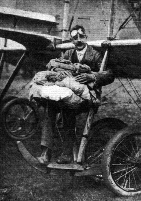
Mr. W. Newell, who has been again making parachute descents at Hendon, comfortably tucked up on his perch, prior to a descent last week-end.
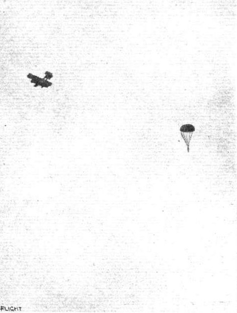
Mr. W. Newell's parachute descent from aeroplane at Hendon. - a distant snap taken a few moments after he had parted from the aeroplane.
Loading up the five-seater Grahame-White biplane at Hendon Aerodrome, as seen from the pavilion.
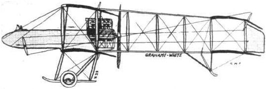
The 100 h.p. five-seater Grahame-White biplane.
Flight, March 14, 1914.
WHAT THERE WILL BE TO SEE AT OLYMPIA.
THE EXHIBITS.
Grahame-White (Grahame-White Aviation Co.). (40.)
ON the stand of the Grahame-White Avation Co., Ltd., will be shown two biplanes, one of which is already known to our readers through descriptions in the columns of FLIGHT, i.e., the five-seater biplane which established a record by carrying ten passengers at Hendon. This machine will be all-British, as it will be fitted with a 100 h.p. Green engine.
The other biplane will be of the pusher type fitted with one of the new Gnome 100 h.p. monosoupape engines. Several highly interesting constructional details have been incorporated in this machine, whilst the general arrangement is such as to make it specially suitable for military purposes. The machine, as shown, will be fitted with a land chassis, but a different form of chassis having floats instead of wheels can be easily and quickly fitted, thus turning the machine into a waterplane. The seats are arranged in tandem, the pilot occupying the front seat, and arranged comfortably inside the very wide nacelle. The method of mounting the engine and propeller is very ingenious, as are also numerous other details, so that a visit to this stand should prove highly interesting and instructive.
Flight, March 28, 1914.
THE OLYMPIA EXHIBITION.
THE EXHIBITS.
GRAHAME-WHITE. (GRAHAME-WHITE AVIATION CO., LTD.)
ON this stand were shown a complete two-seater biplane and the central portion of the Grahame-White five-seater biplane which established a record at Hendon by carrying ten passengers.
<...>
The 100 h p. Naval and Military Biplane is shown to the public for the first time. It is a biplane of the "pusher" type and derives its name from the fact that the land chassis with which it is fitted at the Show can be easily and quickly replaced by a float chassis, thus converting it into a seaplane.
The engine, a 100 h.p. Gnome monosoupape, is mounted between double bearings, and drives through a chain and sprocket gearing a large diameter four-bladed propeller, geared down in the ratio of 14/23. The tanks have a capacity of 45 gallons of petrol and 9 gallons of oil, or sufficient for a flight of about 5 hours' duration. The nacelle is built up of longerons of ash with struts and cross members of spruce, ash, hickory and steel. The rear portion of the nacelle covered with an aluminium shield, which almost totally encloses the engine, whilst the remainder of the nacelle is covered with fabric. The pilot's and passenger's seats are arranged tandem fashion, the pilot occupying the front seat. They are built up of steel tubes, wicker covered, and slung from the longerons of the nacelle by steel wires. Control is by means of a single central column and a foot bar. The column terminates in a convenient grip or handle, on which are mounted the two switches, the main switch and the cut-out switch. The chassis is of a very simple type, and is built of streamline steel tubes, running from three points on the nacelle, converging towards the wheel axle, which works in a slot in the upright chassis strut. Springing is by means of rubber cord, and is further enhanced by the fitting of large size tyres to the disc wheels.
The main planes are chiefly remarkable on account of the backward slope of their outer portion. Both upper and lower main planes are fitted with ailerons, which, owing to the backward slope of the trailing edge, have the same effect, to a certain extent, as a warping wing. Two pairs of spruce struts on each side separate the main planes. These struts are very wide and comparatively thin, and are of an excellent streamline section. The tail planes are carried on an outrigger formed by four tail booms of wood, which form a V as seen in plan. The method of attaching these tail booms to the rear spars is very ingenious, and is illustrated by one of the accompanying sketches. It will be seen that they can be very quickly and easily dismantled, thus reducing the overall length of the machine for the purpose of storage or transport. The stabilising plane is semicircular, and carries at its rear edge the divided elevator, whilst pivoted on the rearmost upright tail boom strut is the balanced rudder. A small vertical fin is mounted above the stabilising plane in order to counteract the side area of the nacelle, but one would venture to suggest that lengthening the tail booms, thus taking the tail planes a little further away from the propeller, would add to what might be termed the spiral stability of the machine. A laminated steel skid protects the tail planes.
The workmanship shown in this machine is of the very highest quality, and is, we think, even better than in any of the machine hitherto turned out by this firm. Altogether the machine appeals to be a thoroughly sound job, and is a credit to its designer. Mr. J. D. North, and to the high standard of workmanship of the Grahame-White Aviation Co.
Flight, May 22, 1914.
THE AERIAL DERBY.
THE PILOTS AND HOW TO RECOGNISE THE MACHINES.
No. 11. The 100 h.p. Grahame-White Biplane.
This machine will be somewhat difficult to distinguish from the Henry Farman if flying at a great altitude, but differs from the latter in that iеs chassis has no skids.
THE MACHINES AND HOW TO RECOGNISE THEM.
No. 11. The 100 h.p. Grabame-White Military Biplane is the machine exhibited at the last Olympia Aero Show. As it has not yet been thoroughly tried, there is the possibility that Mr. Louis Noel will change this machine at the last moment for an 80 h.p. Morane, in which case the total number of Moranes flying in the race will be five. The military biplane is mainly characteristic on account of the main planes, of which the outer portion is slightly swept back. The nacelle is also of a somewhat peculiar shape, being, so to speak, of streamline form flying with the pointed end foremost. The engine, a 100 h.p. Gnome, monosoupape, is totally enclosed by an aluminium shield. The landing chassis is of a simpler type than one usually finds in biplanes of the "pusher" type, and is somewhat similar to the chassis of the Morane-Saulnier monoplane.

This photograph gives a good idea of the general arrangement of the new Grahame-White military biplane. At present the pilot occupies the front seat, but when the machine has been put through its experimental tests it is intended to reverse the positions of the pilot and passenger so as to allow of mounting a gun in the nose of the nacelle.

Front portion of the new Grahame-White two-seater.
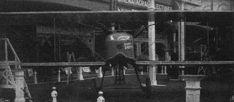
Front view of Grahame-White two-seater biplane.
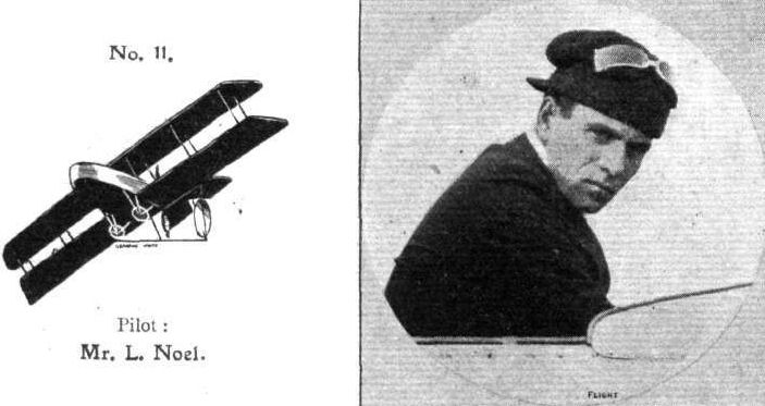
Pilot: Mr. L. Noel.
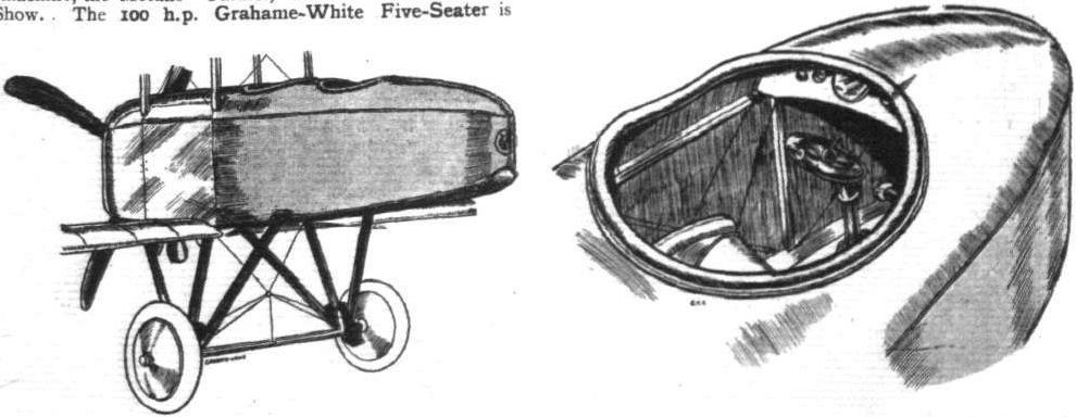
Nacelle and chassis of Grahame-White two-seater. Right, the pilot's cockpit.
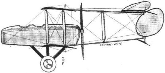
The new 100 h.p. Grahame-White biplane.
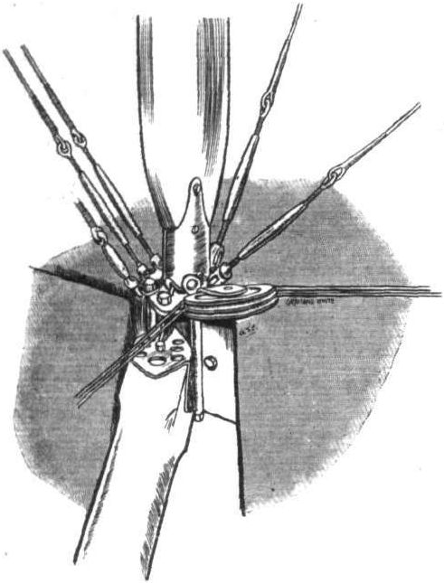
Method of joining plane strut and tail boom to rear spar.
Flight, August 28, 1914.
THE "ROUND BRITAIN" MACHINES.
THE machine officially numbered 4 in the Circuit of Britain was
The Grahame-White Tractor Biplane,
which was to have been piloted by Mr. Grahame-White. During one of its trial flights this machine, it will be remembered, was damaged on alighting, but previously it had shown that it was capable of doing all it was designed to do; in fact, in several respects it exceeded the expectations of its designer, Mr. J. D. North.
To the casual observer the Grahame-White tractor does not differ a great deal from other machines of its type, but a close inspection reveals a number of interesting features, ingeniously conceived and well carried out. One outstanding feature is its small size - the span is only 27 ft. 10 ins., whilst the over all length is just over 27 ft. - which gives one an impression of speed, an impression that is confirmed by actual figures, for the maximum speed is stated to be 85 m.p.h., and that figure can probably be exceeded.
The fuselage resembles that of the Morane monoplane in that it terminates in a horizontal knife-edge at the rear. In section it is rectangular, and the joints between struts, cross-members, and longerons are formed, in the rear portion, in a manner similar to those of the Morane, whilst in front, owing to the different weight disposition, the joints are of varied form.
In the extreme nose of the machine is mounted a 100 h.p. Gnome monosoupape engine, supported on three bearings, of which the front one is self-aligning. An aluminium shield encloses the greater part of the engine and extends backwards up to the passenger's seat. A turtle back consisting of three ply wood in front and stringers covered with fabric in the rear, tops the fuselage.
Pilot's and passenger's seats are arranged in tandem, the former occupying the front seat, which is built into the petrol tank, situated between pilot and passenger. Lateral and vertical control is by means of a single central tubular column, terminating in an elliptical handle on which is mounted the engine switch. A to-and-fro movement operates the elevator, whilst the ailerons are actuated by rocking the lever from side to side. Foot steering is effected by means of a pivoted foot bar mounted on the floor of the fuselage.
In the arrangement of the main planes several departures from usual practice are to be found, notably in the method of strutting employed. Only one set of struts is fitted on each side, but this comprises three instead of two struts. In addition to the struts connecting front and rear spars of upper and lower planes respectively, a third strut runs from the front spar of the lower plane to the rear spar of the upper plane. On account of the very pronounced stagger, this third strut is nearly vertical and is in the same plane as the diagonal bracing cable running from the fuselage to the attachment of the strut to the upper rear spar. From a steel clip on the lower longeron other cables run to the upper extremities of front and rear struts. This method of bracing is somewhat unusual, but in the opinion of the designer combines great strength with low head resistance. The struts themselves are of unusual construction, in so far as they consist of steel tubes totally enclosed in streamline wood casings, a construction which renders them immensely strong. They are attached by means of steel clips gripping the spars without piercing them. The latter are of hollow section and bound with fabric, and during a test to which one of these spars was subjected it carried a load of eight times the weight of the whole machine without any perceptible deflection.
In addition to the heavy stagger the main planes are interesting on account of the fact that the lower plane is set at a smaller angle of incidence than the upper one, the two angles being 3° and 5° respectively. The object of this arrangement is to improve the longitudinal stability of the machine, and the results obtained in practice show that it answers its purpose, A dihedral angle of 2° to the lower plane increases the lateral stability. The upper plane, which is straight, is fitted with interconnected ailerons. In order to give a good view from the pilot's seat in a downward direction, the trailing edge of the lower plane has been cut away near the fuselage. From the passenger's seat the view in a forward and downward direction is practically unobstructed, and that it is comparatively easy to get out of in case of a smash was proved by Mr. North recently, when he managed to "bubble" to the surface when his seat was totally submerged.
At the rear of the fuselage are carried the tail planes, which resemble those of the Morane monoplanes as regards the elevator. No stabilizing plane is fitted, but a vertical fin extends forward from the rudder. A small metal float takes the weight of the tail planes when the machine is at rest.
The chassis consists of two floats, carried on a structure of four stream-line steel tubes, held rigid by means of stout stranded cables.
With full load on board, including 50 gallons of petrol, 9 gallons of oil, or sufficient for a flight of 5 1/2 hours' duration, passenger and pilot, the machine develops a speed of about 85 m.p.h.
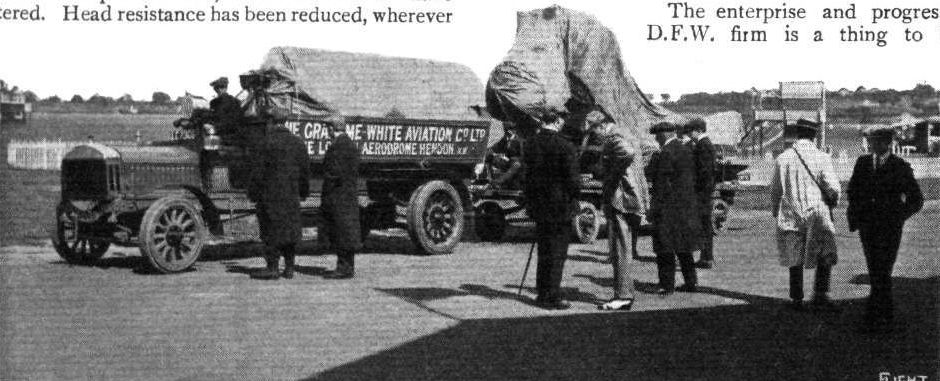
The G.-W. waterplane, contracted for the Circuit of Britain, leaving Hendon for Southampton on Saturday last.
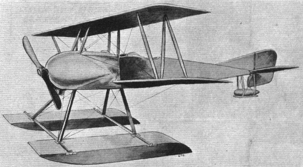
ROUND BRITAIN MACHINES. No. 4. - GW Type XIII Circuit of Britain biplane in seaplane form.
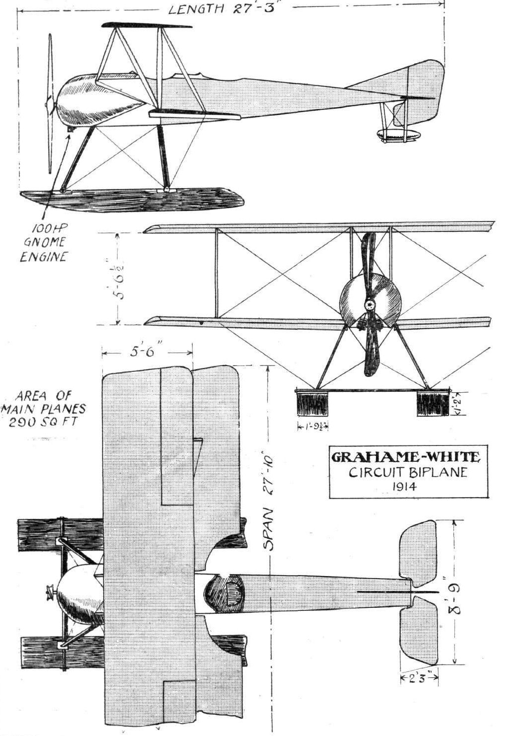
ROUND BRITAIN MACHINES, No. 4. - The Grahame-Whlte tractor biplane. Plan, side and front elevations to scale.
Flight, March 14, 1914.
WHAT THERE WILL BE TO SEE AT OLYMPIA.
THE EXHIBITS.
Hamble River (Hamble River, Luke and Co.). (68.)
ON the stand of the Hamble River, Luke and Co. will be shown a seaplane which, whilst following standard lines as regards its general arrangement, is interesting from the point of view of construction. The nacelle, as will be seen from the accompanying sketch, is of cigar shape, and carries at its rear end a 150 h.p. N.A.G. engine. The main floats, of which there are two, are of rather novel design, and incorporate in their construction several new and interesting features. For the design of this machine, we understand Mr. F. Murphy, formerly connected with the British and Colonial Aeroplane Co., is responsible, and, although this machine has not as yet been tried, there is little doubt but that it will give a good account of itself in the future, and thus become a valuable addition to the list of British seaplanes.
Flight, March 28, 1914.
THE OLYMPIA EXHIBITION.
THE EXHIBITS.
HAMBLE RIVER (HAMBLE RIVER, LUKE AND CO.).
UNFORTUNATELY the seaplane exhibited on this stand was not completely finished at the opening of the Show, and the temporary wiring up of the machine was hurriedly done, so that it is to be feared that a great number of the visitors received an unfavourable impression of the quality of workmanship in it. This is much to be regretted since it is the first time the machine has been shown in public and the workmanship is really very good. When one or two minor alterations have been effected and the machine has been properly tuned up, there is little doubt but that it will give a good account of itself.
In its general arrangement, the seaplane follows standard practice, being a biplane of the "pusher" type and having two main floats and two tail floats. The upper main plane is straight whilst the lower plane is set at a very pronounced dihedral angle in order to provide ample clearance when the machine is rolling.
The two main floats are built up of two skins of cedar, the inner one of which is laid on diagonally over a framework of spruce and rock elm. The floats are divided into watertight compartments by double bulkheads, and a layer of canvas, soaked in varnish, is placed between the two skins. All the chassis struts carrying the floats are steel tubes, and it is intended, we understand, to provide springing of the floats by means of telescopic tubes and coil springs.
The cigar-shaped nacelle is of similar construction to that of the floats, and provides accommodation for the pilot and passengers. The seats are arranged tandem fashion, and the pilot controls the machine by means of a single vertical lever and a pivoted foot-bar. In the rear of the nacelle is mounted the engine, a 150 h.p. British N.A.G., which drives directly a Normale propeller.
The tail unit is carried on an outrigger consisting of four tail booms of spruce connected by struts of the same material. These booms, one gathers, will later be replaced by steel tubes in order to provide a more rigid structure. The undivided elevator is hinged to the trailing edge of a fixed, non-lifting, stabilising plane, under the ends of which are mounted the twin rudders. Two small metal floats support the tail planes when the machine is at rest.
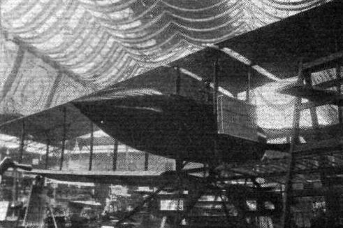
The Hamble River Co.'s seaplane.
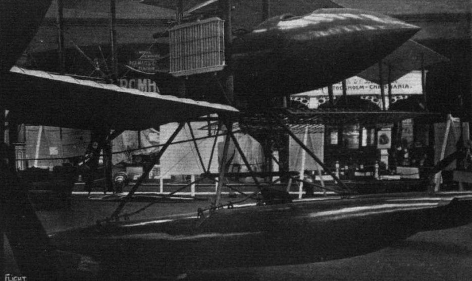
Nacelle and floats of Hamble River seaplane.
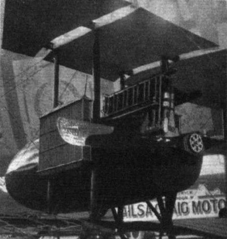
Engine mounting on Hamble River seaplane.
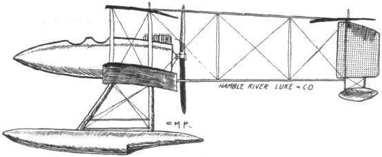
The 150 h.p. Hamble River seaplane.

The seaplane dinghy and one of the floats of the Hamble River machine.
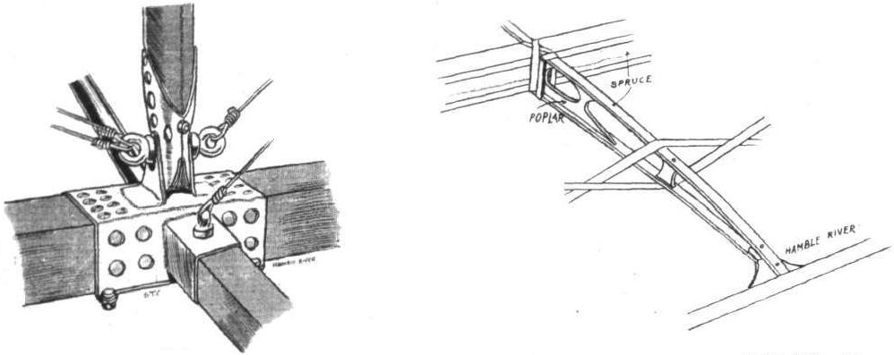
The steel clip connecting the main spars, inter plane strut, compression tube and tall boom of the Hamble River seaplane, and a detail of wing construction.
Flight, May 22, 1914.
THE AERIAL DERBY.
THE PILOTS AND HOW TO RECOGNISE THE MACHINES.
No. 8. The 100 h.p. Handley Page Biplane
will be one of the easiest machines to identify, owing to the peculiar shape of its wings which, as will be seen from the silhouette, are crescent-shaped.
THE MACHINES AND HOW TO RECOGNISE THEM.
No. 8. The 100 h.p. Handley Page Biplane is the same machine on which Mr. E. R. Whitehouse, and later Mr. W. R. Ding, have been doing such good flights. Some time ago, it will be remembered, Mr. Ding damaged the chassis of this machine on landing. The new chassis fitted is of a different type, consisting of two pairs of V struts, from which is slung the single tubular axle. A very effective silencer has been fitted to the 100 h.p. Anzani engine, so that the machine cannot be heard when flying at an altitude of a few hundred feet.
Flight, May 29, 1914.
CROSS-CHANNEL ON THE HANDLEY PAGE BIPLANE.
THE merits of the Handley Page biplane, with 100 h.p. Anzani motor, were strikingly brought out in the flight which was made on Thursday last by Mr. W. Rowland Ding, with Princess Ludwig of Lowenstein-Wertheim, from Hendon to Calais. He left Hendon Aerodrome at 7.40 a.m., and reached Eastbourne at 8.45 a.m. After waiting for the fog to clear in the Channel, he left Eastbourne at 3.30 p.m., and flying to Dover flew across the Channel in the record time of 15 mins., and landed at Calais at 4.20 p.m. There the Princess joined the train and went on to Paris. The next day Mr. Ding left Calais at 8 a.m. and flew across to Staplehurst, in Kent, after having a rather nasty moment in the channel, as for a few moments the engine hesitated and the machine began to glide down. However, the engine picked up all right and flew safely through to Staplehurst. Here he had breakfast and filled up the aeroplane's tanks with petrol. He arrived safely at Hendon at 11.30 am.
It will be recalled that Mr. Ding only obtained his pilot's certificate on April 28th, and these were his first long cross-country flights.
On Tuesday, Mr. Ding set off from Hendon for Bath about 5 a.m., but owing to his compass going wrong he found himself over Southampton Water. Turning to the north-west he got to Salisbury Plain, where he made a landing. Later he flew over to Bath in 22 mins.
Flight, August 28, 1914.
LOST IN THE CLOUDS.
By W. ROWLAND DING.
THE most terrifying experience I have had since I have been flying, and really the most marvellous that any aviator could well have, occurred to me when flying from Bath to Harrogate. Setting out from Bath very early one morning, about five o'clock, and intending to fly straight through to Harrogate without a stop, I found the conditions practically perfect, with the sky beautifully clear, and not a cloud to be seen. Before very many miles had been covered, however, in the distance I saw a little fleecy cloud just making its appearance. It looked quite thin and very innocent indeed, and I thought the best way would be to get over the top of the cloud and continue on my way by the aid of the compass. Having risen over the top of what appeared to be the little cloud, I found that it got larger and larger, the ground being quite hidden from sight; there was simply a beautiful level sea of fleecy white clouds underneath me. I felt quite happy, because the compass appeared to be doing its work, the machine was going well, and the engine running beautifully.
Then the sea of white cloud began to rise gradually, when I naturally pulled up the nose of the aeroplane a little and climbed up what looked like the side of a big snowy mountain. After keeping on for some time, getting higher and higher, one of the plugs in the engine, probably owing to becoming fouled with oil, mis-fired. Thus having one cylinder cut off, the machine could not climb quite so rapidly, and as the surface of the cloud itself seemed suddenly to take a very steep ascent, this meant that I had either to come down below it or else continue on straight through the cloud. The extent of the latter being an unknown quantity, I thought the best thing would be to dive down until I was underneath it. Switching the engine off, I started diving down from a height of between 3,000 and 4,000 ft., the cloud getting thicker and thicker until I could not see even the aeroplane itself. In fact, I could only just distinguish the instruments in front of me, about 2 ft. from my face.
Of course I was watching the height recorder very intently and very anxiously, because it was a great surprise to find that the cloud was so deep. I thought I should soon be underneath it and have a clear view of the ground from about 2,000 or 3,000 feet. I went on diving for a long time, until to my horror the height recorder registered nothing, which meant that I must be very near the ground.
As I was unable to see anything at all, I thought the best thing to do would be to make the machine fly as slowly as ever it could. I knew sooner or later I should have to hit something, and so the best thing was to hit it very slowly instead of very fast. Fortunately the engine I have - the Anzani - throttles down beautifully, and I managed to slow it down till the aeroplane was only travelling at about 35 miles an hour, and with teeth set I continued at this pace until suddenly - we hit the ground. Under such conditions a perfect landing could hardly be expected, and it is something to record that there was very little damage done to the aeroplane itself - in fact it was flying again in two days' time. When the fog cleared, giving me an opportunity to take my bearings, I found that I had landed in a barley field, about a mile and a half outside Stroud in Gloucestershire, and the most wonderful part was, that it was the only field for many miles around on which a landing was possible. All round were thick forests and very high hills. I had motored to Stroud a good many times previously, and scoured the whole district round to look for a suitable ground on which to give exhibition flying, but there was never a one to be found, and ultimately I had to give it up as a hopeless job. However, from the above it will be seen that my Handley-Page biplane was more successful and found a ground of its own accord. I may congratulate myself, therefore, upon the very lucky ending to what might easily have been a much more serious, not to say tragic, affair.
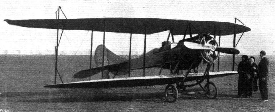
Mr. Rowland Ding in the Handley Page biplane, with Princess Ludwig of Lowenstein-Werthelm in front, just before their departure from Hendon to fly across the Channel, en route for Paris.
The Handley-Page and Avro biplanes ready to take the air at Hendon.
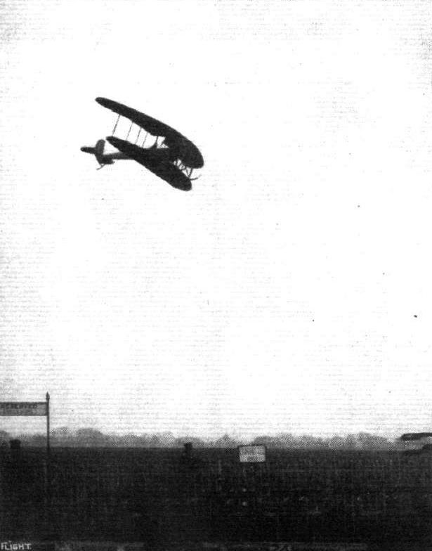
Mr. Whitehouse flying the Handley Page biplane, with the tail planes removed, at Hendon.

A plan view, from beneath, of the Handley Page biplane with the tail planes removed.
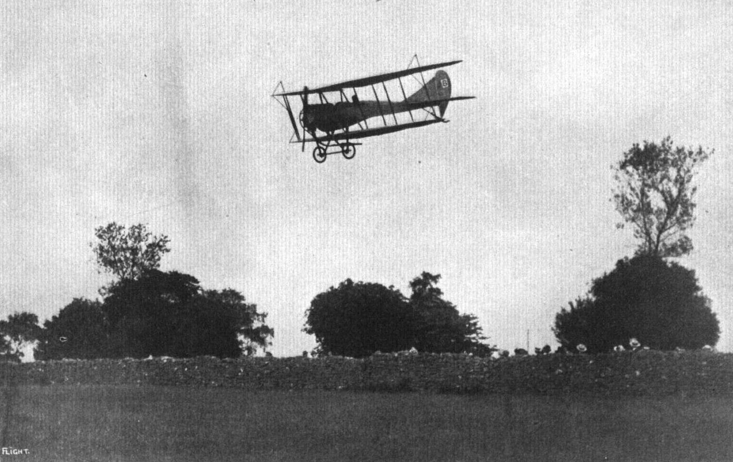
Mr. W. Rowland Ding, flying the Handley-Page biplane at Bath recently.
The Handley-Page G Type biplane, first flown in 1913 and adopted by the RNAS in 1914 for training and home defence.
The Handley-Page G Type biplane, first flown in 1913 and adopted by the RNAS in 1914 for training and home defence.
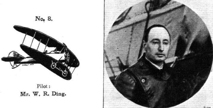
Pilot: Mr. W. R. Ding.
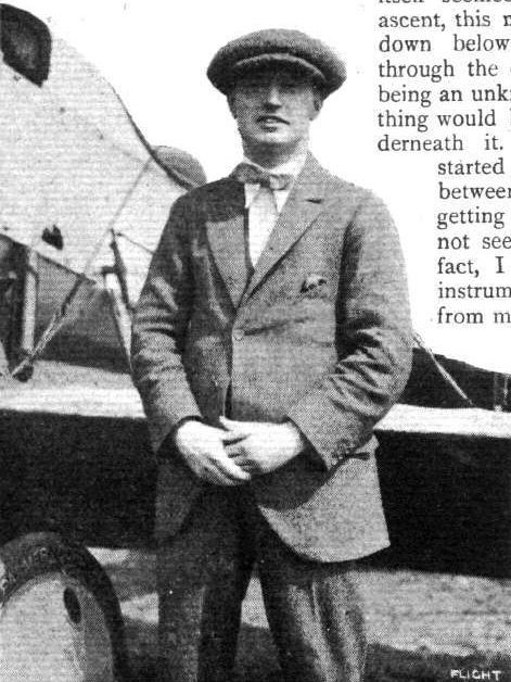
Mr. W. Rowland Ding.
Flight, May 2, 1914.
BRITISH NOTES OF THE WEEK.
Flying in South Wales.
ON Monday, of last week, Mr. H. H. James, one of the James Brothers, made a trial flight of 20 mins. duration, at Narberth in South Wales, on a 45 h.p. Anzani-Caudron type biplane, which is said to be the first aeroplane to be built in Wales. The following evening J. H. and H. H. James each made cross-country flights of half an hour. The next day, H. H. James was out for a high flight, reaching 3,000 ft., but only remained aloft about 20 mint., as the air was choppy.
Flight, July 3, 1914.
EDDIES.
The James brothers, who, it will be remembered, got their ticket at the Caudron School at Hendon, and who have been doing a considerable amount of flying in Wales on a machine of their own make, are now in a position to commercially manufacture their machines, and have established an aeroplane factory at Narberth, their home town. They can thus claim to have established the first Welsh aeroplane factory. I feel sure that our readers will join me in wishing them every success in the venture.
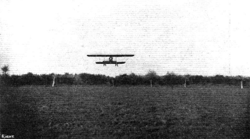
A snap of the brothers James on their biplane at Narberth, South Wales, where they are doing regular air work. The photograph shows the machine getting off in a field with the limited space of 200 by 220, which should give good practice for cross-country work.
Flight, November 13, 1914.
WATERPLANE FLYING AT WINDERMERE.
ALTHOUGH comparatively little has been heard with regard to the activities of the school and works of the Lakes Flying Co., on Lake Windermere, a good deal of constructional and school work has been done, resulting in the production of several school machines and a number of pilots, some of whom have turned out really fine flyers. Under the management and direction of Mr. E. W. Wakefield, who has up to quite recently been the director and owner of the Lakes Flying Co., a machine of original design has been evolved and given excellent results, which does its designer, Mr. Gnospelius, as well as its constructors, the Lakes Flying Co., credit.
Arrangements have now been considered for the Northern Aircraft Company, Ltd., whose director and manager, Mr. W. Rowland Ding, is well known as a particularly successful pilot of the Handley Page biplane, to take over the whole business of the Lakes Flying Co., including the hangars, machines, plant, &c, and it is intended to start immediately with the school and works. The present equipment of the school comprises three machines, including the new monoplane referred to above, whilst the construction of new machines will be commenced at once. As Mr. W. Rowland Ding, in addition to being an experienced pilot, is also a capable designer, the appearance of the new machines will be awaited with interest.
It seems likely that the new school will quickly become popular, for Lake Windermere is in a very attractive flying venue, owing to its elongated shape, a "straight" of eight miles in length and an average width of about three-quarters of a mile, increasing in places to slightly over a mile.
As most of the tuition work will take place over the lake, the danger of serious accident should be remote, especially as a motor boat of 12 h.p. is always in attendance upon the waterplanes. Apart from the waterplanes it is intended to build several land-going machines, so that pupils will have an opportunity of making themselves acquainted with the handling of both types. Attached to the school is also a very fine hydroplane, fitted with a 50 h.p. water-cooled Clerget engine. This boat has a speed of about 50 m.p.h., and will carry four passengers. It will be at the disposal of the pupils, and should form one more attraction to the, in this respect, already well-provided school.
Mr. Ding's own description of his first experience with the water monoplane, of which we hope to be able to give full details later, forms very interesting reading, and, incidentally shows how easily a capable pilot, who has had no previous experience with waterplanes, can master the handling of this type of aircraft. Mr. Ding puts his initial efforts on the Lakes machine as follows :-
"On arriving at Windermere I found that there were three machines: 1. The 'Water-Hen,' the Farman-type biplane with front elevator, built by the Lakes Flying Co., of which a description, with scale drawings, appeared in FLIGHT some time ago. 2. A 50 h.p. Gnome-Avro biplane. 3. A very interesting 80 h.p. 'pusher' monoplane, designed by Mr. Gnospelius and built by the Lakes Flying Co., this machine being not quite finished.
"I decided at once that the third machine was the one which would probably put up the best performances, and I therefore packed the others in different hangars out of the way and set to to finish it off. As soon as finished I had this machine placed on its bogey and run down into the lake, and after a short preliminary run of the engine, which behaved splendidly, I set off on my first waterplane trip.
"I may say that I have never seen a waterplane in the air, and only know what it looks like from photographs. It was with some fear and trepidation that I opened the engine out and waited to see what would happen. One or two seconds after I started I found that I had not the throttle adjusted quite right, and therefore began to adjust it in order to get more speed out of the engine. So busy was I doing this that I did not notice that I had left the water and got some 20 feet into the air, and when I found what had happened I felt very relieved indeed, as I had been told that about the first thing I would do would be to get the front of the float under the water and turn a somersault!
"The machine felt so nice in the air that I took it straight up to about 600 or 700 ft., and managed to do quite small circuits. I found out, however, that the side areas were all wrong, and the machine had a great tendency to spin, this being probably due to the fact that it has a very large square-sided body, protruding out in front of the machine a la Henri Farman, with not much fixed tail area at the back to counteract it. After the first flight I therefore had a large fin made and fitted to the rear of the machine, and, on trying it again, I found that this was a wonderful improvement, as the machine now seems as nice to handle in the air, although somewhat slow, as any I have tried, and there is no tendency to spin at all. The third flight I made with a passenger of about 12 1/2 stone, and this flight was quite successful. The machine lifts a passenger quite well and will do as small circuits as any machine I have seen.
"I find landing on the water quite as easy as landing on terra firma, except perhaps when the Lake is so smooth that it looks like glass, but one soon gets used to this too.
"I am sending you several photographs of this new machine, which deserves to be noticed, as it is of a type which is distinctly original, and which, if it was a little faster (its present speed being about 55 m.p.h,), would be as good a flying machine as any in the country, especially considering that at present it has on it a somewhat heavy and old 'single' float which was not designed for it."
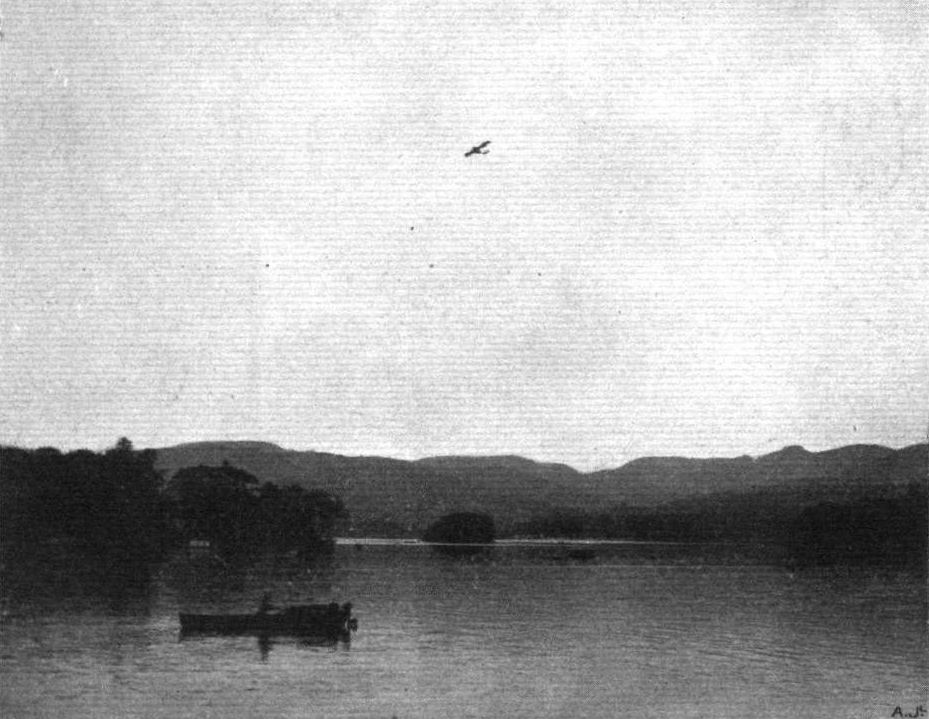
Mr. Rowland Ding well up over Lake Windermere on the waterplane.
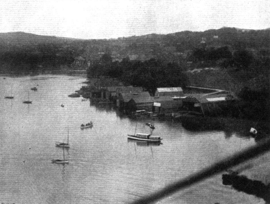
View of Bowness and part of Lake Windermere, showing the Lakes Flying Co.'s hangar as seen from the waterplane.
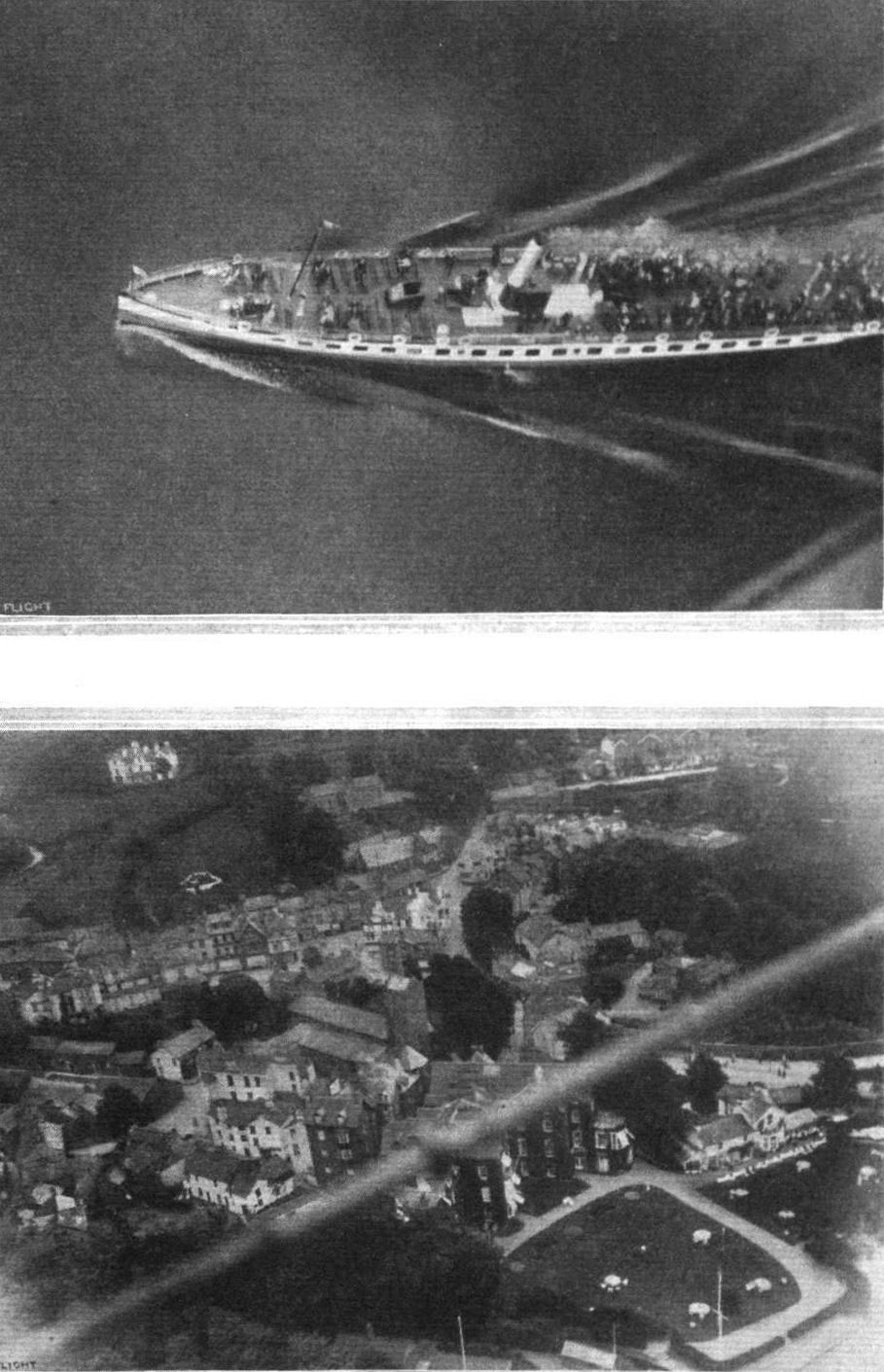
A couple of views taken at Windermere from Mr. W. Rowland Ding's waterplane. The top photograph shows one of the passenger steamers crossing Lake Windermere, and the lower photograph is a near view of Bowness.
Flight, May 2, 1914.
THE CEDRIC LEE MONOPLANE.
As in the early days of the Dunne machine, considerable mystery enshrouds the Cedric Lee monoplane, practical experiments with which have been carried out at the Shoreham aerodrome for some months past. Not the least point of interest in connection with the Cedric Lee monoplane is that it is more or less at variance with certain aerodynamical theories as accepted to-day. Unfortunately, detailed particulars of this interesting machine cannot at present be placed before our readers, as the Cedric Lee Co. do not yet wish these to be made public. Since, however, several successful flights have been made in public, and as entries have been made for the coming Gordon-Bennett race, the following brief particulars, together with the accompanying illustrations, should be of special interest. The most important feature of this machine is that it flies "pterygoid," that is, like a dart, or its length is greater than its span. The latter, in fact, is only some 20 ft. The planes are annular in plan form, being centrally divided fore and aft by the fuselage. The whole of the plane section in side elevation forms one large camber, but the front portion of the plane is also cambered. The covered-in fuselage is rectangular in section, tapering to a vertical knife-edge at the rear. In the middle of the fuselage, in the "hole" of the plane, are the passenger's and pilot's seats, the former occupying the front one, where an excellent view below can be obtained. The engine, a 50 h.p. Gnome, which drives a tractor screw, is placed inside the fuselage in front of the passenger's seat, air scoops being fitted in the sides of the fuselage for cooling. Hinged to the rear extremity of the plane are two elevators, whilst two others are mounted above them, one on each side of the vertical rudder, which is hinged to the rear end of the fuselage and to a vertical fin mounted on to top of the latter. A strong three-wheeled chassis is fitted, one wheel being right in front to protect the propeller. It is claimed that this particular model has a speed range of from 45 m.p.h. to well over 70 m.p.h. Strong construction is another of its features; on one occasion a landing was made on one of the "wing tips," but the machine only rolled a little way on the outer edge of the plane and then settled down on its chassis again without any ill effects. Mr. Gordon England has made several flights on this machine, and just recently Gordon Bell has joined the Cedric Lee Co., and has also made several flights. Unfortunately he met last weekend with one of those accidents that must always j be associated with valuable experimental work, so that activities will be delayed for the present, but we understand that the two machines for the Gordon-Bennett are well in hand at the works.

The Cedric Lee machine in flight.
Flight, September 18, 1914.
EDDIES.
Messrs. M. J. Lindsay, M. G. Smiles, and W. Warren, who in combination are the London and Provincial Aviation Co., are to be congratulated on the first machine they have turned out. Although not claiming any high originality for their first-born, which, as mentioned in "Eddies" a short while ago, in its general appearance is very similar to the Caudron biplanes, these collaborators have turned out an excellent job, the workmanship of which is of very high quality. On a trial flight the other day the 'bus lifted remarkably well, and the new school should soon be busily at work with pupils, especially as another machine is already being completed with all possible speed. The suitability of machines similar to the L. and P. for instruction purposes, even when fitted with a low-powered engine, has already been amply proved. Under the instruction of Warren, who obtained his "ticket" at the Caudron school quite a long time ago, and has had long experience in constructional and repair work, and who will be assisted by Smiles, who "graduated" from the G.W. school, pupils joining the L. and P. School should make as rapid progress as is consistent with thorough tuition.

Three-quarter fiont view of the L. and P. biplane.
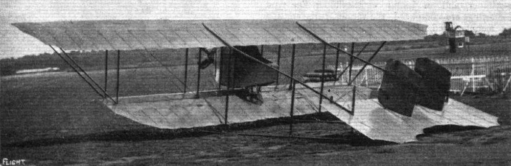
Three-quarter rear view of the 35 h.p. L. and P. biplane.
THE CONSTRUCTORS OF THE L. AND P BIPLANE. - From left to right: G. W. Smiles, W. Warren, H. S. Gist (the man who built the nacelle), and M. J. Lindsay.
Flight, May 22, 1914.
THE AERIAL DERBY.
THE PILOTS AND HOW TO RECOGNISE THE MACHINES.
No. 16. The 120 h.p. Martinsyde Monoplane.
This machine is easily distinguished from the other monoplanes entered by its tapering wings, which are set at a dihedral angle and by its long narrow fuselage.
THE MACHINES AND HOW TO RECOGNISE THEM.
No. 16. The 120 h.p. Martinsyde Monoplane differs in minor details only from the machine flown by Mr. R. H. Barnwell in last year's Aerial Derby, when, it will be remembered, Mr. Barnwell obtained second place, so that this machine should, barring mishaps, be in the first batch home. It is equipped with a 120 h.p. Austro-Daimler engine.
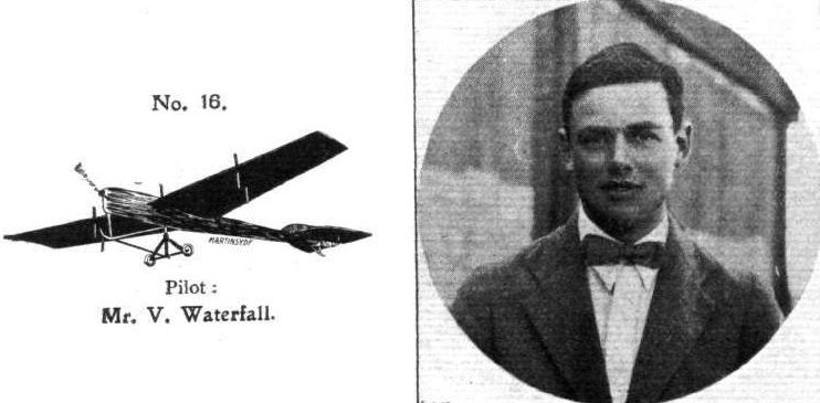
Pilot: Mr. V. Waterfall.
Flight, May 22, 1914.
THE AERIAL DERBY.
THE PILOTS AND HOW TO RECOGNISE THE MACHINES.
No. 5. The 65 h.p. Martinsyde Biplane
looks somewhat similar to the Henry Farman biplane when in the air, but may be differentiated from the latter machine by means of its chassis, which has no skids, and by the different shape of its tail planes.
THE MACHINES AND HOW TO RECOGNISE THEM.
No. 5. The 65 h.p. Martinsyde Biplane. - Although this machine follows more or less standard practice as regards its general arrangement, its performance will be watched with interest, since it is the first time that it appears in public. It is built of steel practically throughout, with the exception of the wings and the engine bearers. The engine used is a 65 h.p. Antoinette, mounted in the rear of the nacelle.
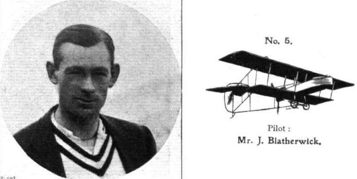
Pilot: Mr. J. Blatherwick.
Flight, June 5, 1914.
EDDIES.
The Martinsyde trans-Atlantic "liner" is growing apace. The wings are ready to be covered, in fact, by the time these lines appear they should be nearly finished; and last week the fuselage was nearing completion. A faint idea of the size of the wings can be obtained from the accompanying photograph. Each wing is built up in two sections, of which the inner section is rigid whilst the outer one can be warped. The workmanship is, as one expects from a firm enjoying such a reputation as Messrs. Martin and Handasyde, of the very highest quality. In its general shape the fuselage resembles those of previous Martinsydes, but constructionally it differs in that cross-wiring is employed instead of the three-ply panels which have always formed one of the characteristics of these machines. I saw the empennage marked out on the floor, and it gave one the impression of having nearly as large area as the wings of some small monoplanes. In addition to the two extra hangars which they have taken in view of all the parts being duplicated, the Martinsyde firm are building a large shed a short distance beyond the Bleriot works in which to erect the new machine.
Flight, August 7, 1914.
EDDIES.
Following on the great monoplane which was built by Martin and Handasyde for the trans-Atlantic flight, and the small scouting biplane now in course of construction at this firm's Brooklands works, I learn that the drawings are being got out for a huge new monoplane. In its general arrangement the latest Martinsyde will follow the lines of its predecessors, but it is understood that the occupants' seats will be differently arranged. The pilot will sit very far back in order to get a good view in all directions, while the passenger's seat will be placed sufficiently far forward to enable him to look beyond the leading edge of the wings.
EDDIES.
The Martinsyde trans-Atlantic "liner" is growing apace. The wings are ready to be covered, in fact, by the time these lines appear they should be nearly finished; and last week the fuselage was nearing completion. A faint idea of the size of the wings can be obtained from the accompanying photograph. Each wing is built up in two sections, of which the inner section is rigid whilst the outer one can be warped. The workmanship is, as one expects from a firm enjoying such a reputation as Messrs. Martin and Handasyde, of the very highest quality. In its general shape the fuselage resembles those of previous Martinsydes, but constructionally it differs in that cross-wiring is employed instead of the three-ply panels which have always formed one of the characteristics of these machines. I saw the empennage marked out on the floor, and it gave one the impression of having nearly as large area as the wings of some small monoplanes. In addition to the two extra hangars which they have taken in view of all the parts being duplicated, the Martinsyde firm are building a large shed a short distance beyond the Bleriot works in which to erect the new machine.
Flight, August 7, 1914.
EDDIES.
Following on the great monoplane which was built by Martin and Handasyde for the trans-Atlantic flight, and the small scouting biplane now in course of construction at this firm's Brooklands works, I learn that the drawings are being got out for a huge new monoplane. In its general arrangement the latest Martinsyde will follow the lines of its predecessors, but it is understood that the occupants' seats will be differently arranged. The pilot will sit very far back in order to get a good view in all directions, while the passenger's seat will be placed sufficiently far forward to enable him to look beyond the leading edge of the wings.
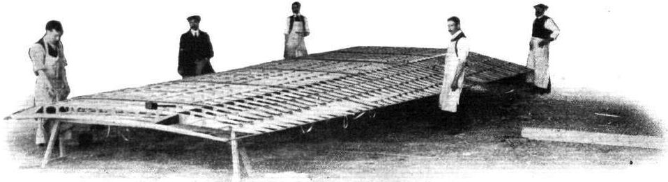
One of the wings "in the making" of the Martinsyde trans-Atlantic "liner."
Flight, June 26, 1914.
EDDIES.
Waterplaning is not, evidently, to be regarded as the sport of the well-to-do, as I hear that the three brothers Mitchell are having an excellent time at Gillingham in Kent, with a machine which they have constructed from their own designs. This machine is a biplane having a span of 37 ft. and 34 ft. for the upper and lower planes respectively - the chord being 4 ft. 6 ins. and the gap 6 ft. At present a 100 h.p. Mors engine is fitted, and the machine when empty weighs 1,050 lbs. Three floats are employed - two main and one tail float - the former, which weigh 50 lbs. each, being rigidly attached to the struts from the body, and tied together by the cross-member seen in the photograph. Ailerons are fitted between the main planes. The machine has not yet been flown, owing to the fact that the locality is within one of the restricted areas, but "taxying" has been freely indulged in. On the last occasion, however, misfortune awaited them, happily without serious results, as the crowd, holding on to the tail, let go before the pilot was ready, with the result depicted in the photograph.
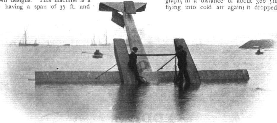
The Mitchell brothers seaplane was taxied on the River Medway in 1914 but capsized before flight was possible.
Flight, February 14, 1914.
A SOUTH AFRICAN-BUILT BIPLANE.
IN sending us the two photographs appearing on this page and page 160, a Kimberley correspondent writes as follows :-
"I enclose two photographs of the South African-built biplane referred to in the communication you received and published (in FLIGHT for November 1, 1912) from the late E. W. Cheeseman. This machine is of special interest because it has been recently purchased by the South African Government, and is their first machine. It is also the first machine built in S.A. which has flown successfully. Mr. Paterson recently made a flight over the Kimberley Aerodrome with this machine of 2 hours 10 mins., covering 120 miles. Unfortunately the Paterson Aviation Syndicate is liquidated, and the beautiful aerodrome will be made no further use of until some enterprising firm turn their attention to the possibilities of success in South Africa."
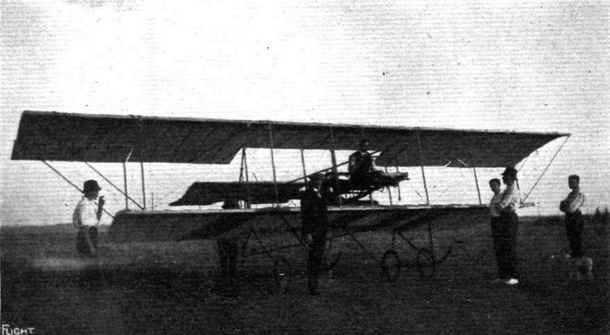
A SOUTH AFRICAN-BUILT BIPLANE. - In the pilot's seat is seen Mr. Compton Paterson, the designer and pilot, and standing on his right is Mr. H. Carpenter, the constructor.

A SOUTH AFRICAN-BUILT BIPLANE. - Final adjustments outside the hangar just previous to its first ascent.
Flight, March 14, 1914.
WHAT THERE WILL BE TO SEE AT OLYMPIA.
THE EXHIBITS.
Pemberton Billing. (49.)
AMONGST the new comers at the Show one of the most interesting will be the flying boat exhibited by Mr. Pemberton Billing. The "Supermarine," as Mr. Billing calls his flying boat, represents radical changes from usual practice in flying boat construction and design. The boat itself, as will be seen from accompanying sketch, is cigar shaped, thus providing a perfect streamline. The construction of the boat is unusual and will be fully described later. The Supermarine is of the tractor type, and it will be seen that the position and attitude of the engine and propeller is highly original inasmuch as they are mounted above the boat and in front of the main planes. It will be interesting to see how this arrangement will work in practice, the theory, of course, being that setting the propeller-shaft at an angle to the boat will facilitate getting off the water.
In addition to the complete machine there will be exhibited on this stand a model of the next Supermarine to be built, which is to be known as the P.B. 2, whilst the present machine is called the P.B. 1. A three-bladed propeller of special construction, and a supermeter for determining the height above the ground or the sea, and described elsewhere in this issue, will complete the exhibit on this stand.
Flight, March 21, 1914.
THE OLYMPIA EXHIBITION.
THE EXHIBITS.
THE SUPERMARINE P.B. 1 (PEMBERTON BILLING). (49.)
AMONGST the newcomers at the Show, one of the most ordinal machines is the flying boat exhibited by Mr. Pemberton Billing. This machine differs radically from any flying boat hitherto turned out in this or any other country, and is an attempt to produce as Mr. Pemberton Billing puts it, a boat that will fly rather than an aeroplane that will float. The construction of the cigar-shaped hull is very interesting. The upper portion of the hull consists of two layers of spruce, whilst the thickness of the lower portion of the hull has been very carefully proportioned according to the strains imposed upon it. Thus at the keel there are five thicknesses of wood, while from the keel towards the deck it gradually tapers off into four, three and two thicknesses. The step of the boat, which forms a separate structure, riveted to the main hull, is built up of spruce, mahogany, rock elm and ash, beginning with the weaker wood near the nose of the boat, and having the strongest wood at the step where the greatest load is taken.
It will thus be seen that strength is obtained where necessary, not only by bulk, but also by careful selection of the materials best suited for the purpose. In addition to this, the circular construction of the hall has the advantage that a pressure applied at any point is transmitted to the whole surface, thereby making it possible to reduce the weight to a minimum and yet preserve the necessary strength. The weight of the hull is only about 200 lbs. Further rigidity is added to the boat by internal cross-bracing of the usual type, and bulkheads divide the boat into watertight compartments. These bulkheads are fitted with manholes in order to allow of adjustment of the internal cross-bracing. In the nose of the boat rests an anchor or grapnel, which, on being released, is shot forward by a strong coil spring. The anchor cable passes round a drum in front of the pilot's seat, so that the pilot is able to lower or hoist his anchor without leaving his seat. Interesting as the design and construction of the boat itself undoubtedly is, the engine mounting is even more so, for instead of mounting the engine as it is usually done, either in the boat itself or between the inner plane struts, Mr. Billing has mounted it in a streamline casing of wood, which also encloses the tanks. The rear portion of this casing is secured to the two front inner plane struts, whilst an additional two struts running from the engine down to the deck of the boat take the weight of the engine, a 50 h.p. Gnome driving directly a three-bladed propeller. The main planes, which are perfectly straight, that is to say, they have no dihedral angle, are set at an angle of incidence of 3 degrees. They are separated by spruce struts, and cross - braced in the usual way by stranded cables. The lower wing tips are protected by floats of a similar construction to that of the boat. By introducing springs in the cross-bracing of the floats these are allowed to travel backwards and upwards, thus adapting themselves to undulations of the water. One of the accompanying sketches shows the tail planes, which are mounted on a small structure of steel tubes. The pilot's seat, which is situated just to the rear of the lower plane rear spar, is made quickly detachable, so that in case of accident the pilot can throw it overboard, and as it possesses sufficient buoyancy to keep a man afloat, it serves the purpose of the lifebelt frequently worn by pilots of waterplanes. Control is by means of a single central lever and a pivoted foot-bar.
In addition to the complete machine, there is shown on this stand a scale model of the Supermarine P.B. 3, which Mr. Pemberton Billing was unable to get finished in time for the Show. This machine will be fitted with two Austro-Daimler engines placed in the hull, and driving the propeller through bevel-gearing. Another interesting item is the Supermeter, which indicates to the pilot his height above the surface from a height of 15 ft. downwards. As this instrument was fully described in these columns last week, further reference is unnecessary. Some examples of the three-bladed propellers with which the Supermarines are fitted will be found to be well worth a careful inspection.
Pemberton Billing supermarine P.B. 1.

The 50 h.p. Supermarine (Pemberton Billing).
View from underneath of the hull of P.B. 1, and on right the step in the hull.
One of the strut sockets on the supermarine P.B. 1, and on the right the tail planes.
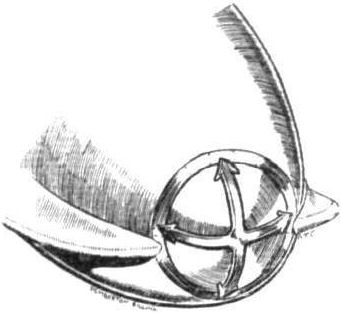
Nose and grapnel of P.B.1.
Flight, August 21, 1914.
THE P.B.IX SCOUTING BIPLANE.
HITHERTO, Mr. Pemberton Billing has confined his attention to the production of seaplanes, but, as mentioned briefly in "Eddies" last week, realising the need at the present time for military biplanes for scouting work, he set to work with commendable enterprise to produce such a machine, capable of being quickly erected and dismantled for transport, and in which the engine might be exchanged for another one of different horse-power in the shortest possible space of time.
In the extraordinarily short period of one week, the designing, construction and finishing of this machine had been completed. The machine would have been put through its trial flights within that time limit but for the fact that there is no suitable ground in close proximity to the supermarine works of Mr. Pemberton Billing at Southampton. As it was, it was tested in the air within the next two or three days, and came well up to its designer's anticipations.
In its general lay-out the P.B. IX Scouting biplane does not differ materially from already existing machines of that type, but its designer has managed to incorporate several cleverly thought out details in the construction. The fuselage, which is of rectangular section, is extremely roomy, and tapers to a vertical edge at the rear. The longerons, which are of ash, converge towards the nose of the machine (when viewed from the side), where they are attached to the front engine bearer. As seen in plan, they run parallel up to the pilot's seat, whence they commence to taper gradually towards the rear. As shown in one of the accompanying sketches, the method of joining struts and cross-members to the longerons of the fuselage is similar to that employed in the Morane monoplanes, and the sketches are self-explanatory.
Mounted between double bearings in the nose of the machine is the engine - a 50 h.p. Gnome is at present fitted, but the fuselage is wide enough to accommodate an 80 if desired - and to the rear of that inside the aluminium cowl in front of the pilot's seat are the petrol and oil tanks, which have a capacity sufficient for a three hours' flight.
In its present form the machine is essentially a single-seater, but the roomy cockpit affords ample accommodation should it be desired to fit an extra seat. Control is by means of a hand wheel mounted on a single central tubular column. Behind the pilot's seat is a transverse rocking shaft, carrying at its ends crank levers from where cables run to corresponding levers on the elevator. Another steel tube connects the vertical control lever with the lower half of the crank-lever on the transverse shaft, thus doing away with crossing of the elevator control cables, which might lead to wear and subsequent breakage.
A fiat non-lifting tail plane is mounted on top of the fuselage and to it is hinged the divided elevator. Pivoted round the tubular extension of the sternpost of the fuselage is the rudder, and a vertical fixed tail fin is fitted. A small sprung tail skid protects the tail plane against contact with the ground.
The main planes are characterised by having their trailing edge slightly longer than the leading edge. They are separated by only two struts on each side, and cross bracing is effected by means of stranded cables. Ailerons are fitted to both upper and lower planes, and are inter-connected by a strut running from the under surface of the upper aileron to the top of the lower one. They are operated by rotation of the hand wheel, and steering is effected by means of a pivoted foot-bar. Near the fuselage the trailing edge has been cut away in order to provide a better view in a downward direction. It is in their attachment to the fuselage, however, that the main planes are chiefly interesting. The spars on both planes run right through the wing from tip to tip, those of the lower plane running underneath the fuselage, to the lower longerons of which they are attached by U-bolts. By undoing these four U-bolts, the wings may be slid over the end of the fuselage and laid on top, and the machine is then ready for transport. This method of attaching the wings has the further advantage that should it be desired to fit an engine of a different horse-power and weight, the longitudinal stability of the machine can be corrected by sliding the wings a few inches backwards or forwards along the fuselage. This feature should be of considerable merit for military purposes, where an interchange of engines may frequently be desirable. Another reason why the light single-seater scout should be useful for military purposes at present is that there are probably a great number of 50 h.p. Gnomes available, fitted to school machines, which would be of no use as military machines, but the engines of which could with advantage be used in a small fast machine of this class.
The chassis is of simple type, and consists of two "V's" of streamlined wood. The axle works in slots in the angle between the front and rear chassis struts. No skids are fitted. The weight of the machine empty is 560 lbs., and with pilot and three hours' fuel, 750 lbs., or a loading of 3-6 lbs. per square foot. The maximum speed with a 50 h.p. Gnome is about 75 miles per hour, and the minimum speed just over 30 miles per hour.
During the preliminary trials a few days ago, already mentioned, P.B. IX got off after a very short run, piloted by Mr. V. Mahl, and appeared to climb at the rate of about 500 ft. per minute.
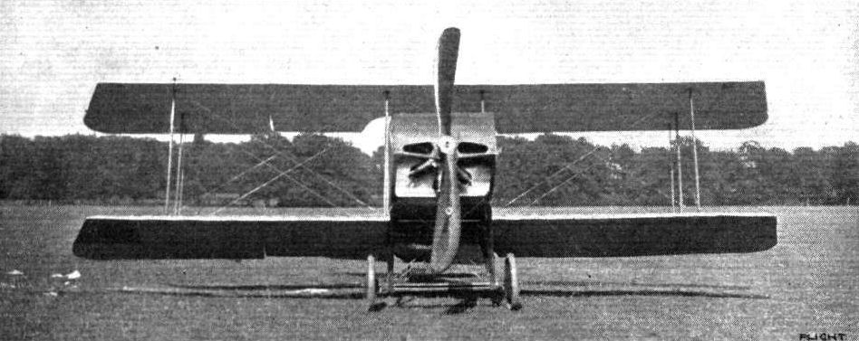
Front view of P.B. IX.
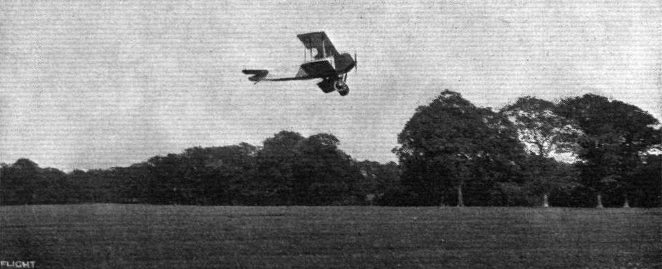
P.B. IX in flight at Southampton.
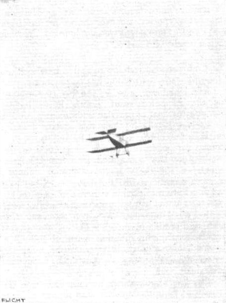
Another view of P.B. IX in the air.
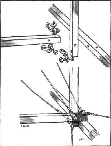
Sketch showing method of joining struts and cross members to fuselage longerons of P.B. IX.
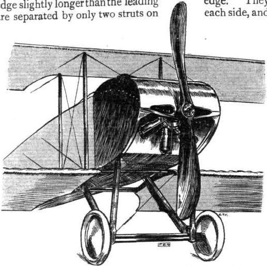
Chassis and engine housing on P.B. IX scouting biplane.
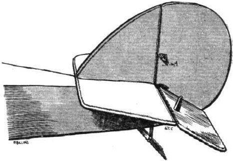
Tail planes of P.B. IX scouting biplane.
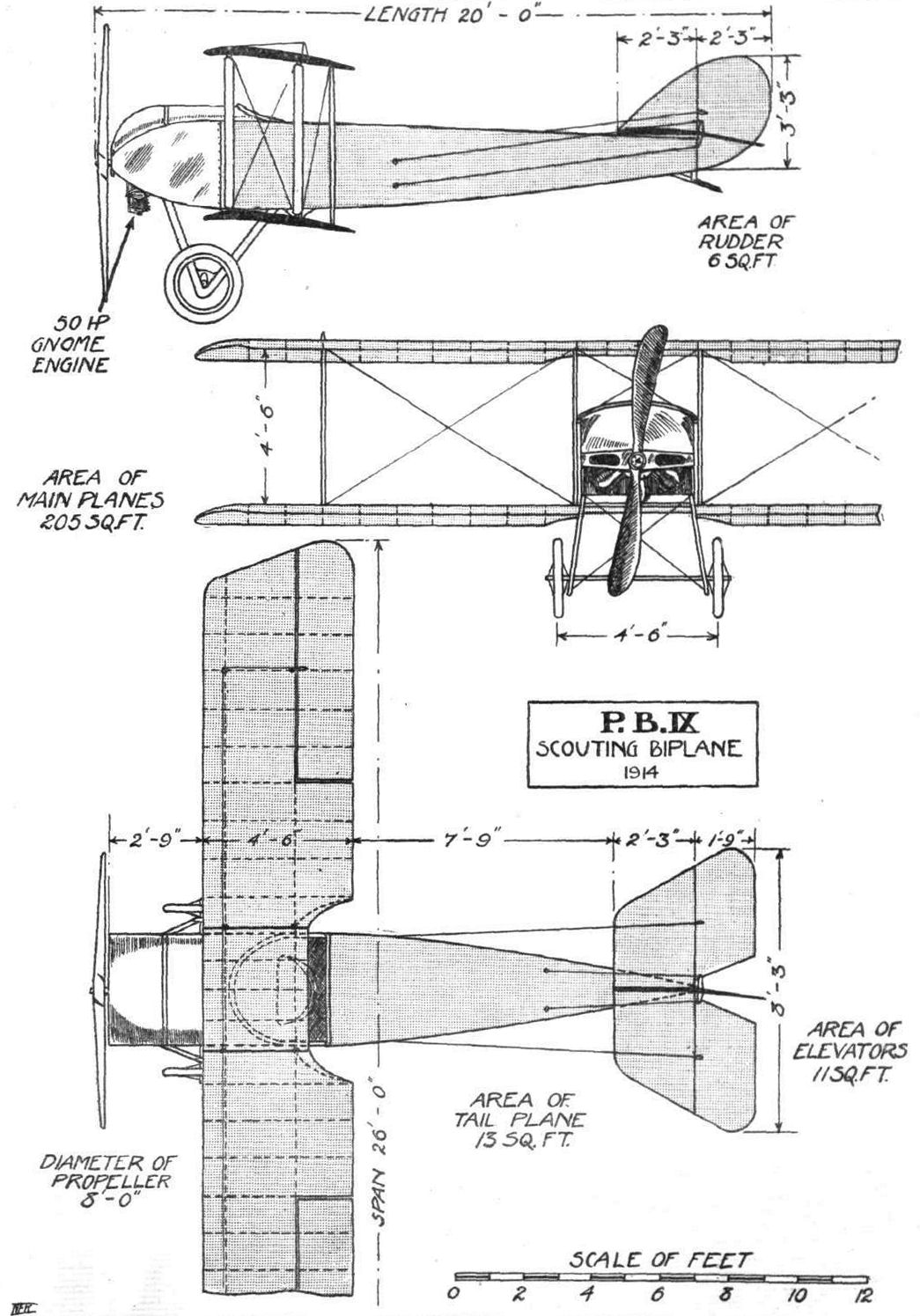
P.B. IX SCOUTING BIPLANE. - Plan, side and front elevation to scale.
Flight, March 14, 1914.
WHAT THERE WILL BE TO SEE AT OLYMPIA.
THE EXHIBITS.
Perry Beadle (Perry, Beadle and Co.). (42.)
ANOTHER newcomer to the Show will be the flying boat exhibited by Messrs. Perry, Beadle and Co.
This machine differs materially both in design and construction from usual practice. From the accompanying sketch it will be seen that the lines of the boat itself are highly original. In front it is very deep and wide, and in this portion of it is housed the engine, a 60 h.p. E.N.V., which drives through chain-and-sprocket gearing the two propellers situated in front of the main planes.
The tail planes are fish-shaped and form a continuation of the boat itself, being of the same material, that is to say, two layers of mahogany. The most interesting point, however, is perhaps the position and construction of the lower main plane. This member is covered with mahogany similarly to the boat, instead of the usual fabric covering, and is partly submerged in the water when the machine is at rest.
Flight, March 28, 1914.
THE OLYMPIA EXHIBITION.
THE EXHIBITS.
PERRY BEADLE (PERRY, BEADLE AND CO.).
THE flying boat exhibited by this firm is of very unusual appearance and represents radical changes from accepted methods of flying bout design. The boat itself, which has been built by Messrs. Saunders, of Cowes, has two skins of mahogany sewn together with copper wire, The tail planes, which are more or less fish-shaped, form a continuation of the hull, and are built up in the same way.
The pilot's and passenger's seats are arranged tandem fashion, the pilot occupying the rear seat. Control is by means of a hand-wheel mounted on a single central column, and a pivoted foot-bar.
Mounted in the nose of the boat on strong longitudinal bearers, the engine - a 60 h.p. E.N.V., is temporarily fitted, but will be replaced later by one of higher horse-power - driving through chain and sprocket gearing the two propellers, situated in front of the main planes. These propellers seem to be of very small diameter, but are really nearly six feet. The combined thrust and journal bearing is supported in a steel casing, which is in turn mounted between the two halves of the front plane strut, the whole being made rigid by the diagonal cross bracing wires. This, of course, necessitates very careful adjustment of the wires, as otherwise the propeller shaft would be out of truth. A very neat streamlined casing of brass encloses the propeller shaft in the manner shown in one of the accompanying sketches. The tubular chain guards serve at the game time as radius rods by taking the compression due to the pull on the chains.
The main planes are separated by hollow spruce struts, and the upper one, which is covered with fabric in the usual way, carries the interconnected aileron. The lower main plane, the trailing edge of which is submerged in the water when the machine is at rest, is covered with two skins of mahogany sewn together, similar to the covering of the boat. No wing tip floats are fitted as the lower plane performs this duty. The arrangement, whilst very unusual, is certainly well worth trying, but one would imagine that for work in a rough sea several objections might be raised against it.
The construction of the boat, as one would expect from a firm like Messrs. Saunders, is excellent.
Perry Beadle and Co.'s stand.
THE PERRY BEADLE FLYING BOAT. - On right the tail planes.

The 60 h.p. Perry Beadle and Co. flying boat.
The Perry Beadle boat with wings removed, and on right strut socket and hinge attachment of wing to fuselage.

Streamline casing round propeller-shaft of Perry Beadle flying boat, and on the right strut socket and aileron pulley.
Flight, January 31, 1914.
THE ROYAL AIRCRAFT FACTORY AND THE INDUSTRY.
ELSEWHERE in this issue we deal editorially with the serious harm which is being done, in certain directions, by the ill-informed and wildly irresponsible criticism, in more or less general terms, directed against everything and everybody associated with the Royal Aircraft Factory. One great crime that looms more largely than anything else appears to be the alleged copying of the good features of machines turned out either here or abroad, the Avro, Nieuport, Blenot, and Breguet being specifically mentioned. Without wishing to detract in any way from the splendid work put into and done by these machines, and for reasons set out in our editorial comment, we have thought it high time that some protest should be raised against this extraordinary series of attacks which can only lead to one certain end, namely, the crippling, not to say annihilation, of the financial possibilities of the industry; and without any bias one way or the other, we have deemed it worth while to investigate in detail some of the so-called "facts" to see if they will stand up to the light of day. From various sources we have gleaned some interesting data, which speak for themselves, and we give the result of our enquiries below, which should be read in conjunction with, and, as it were, as an appendix to, our editorial comment already referred to.
The first design of aeroplane built at the R.A.F. was known as the F., or the Farman type; the second, the S.E., was illustrated in FLIGHT for July 15th, 1911, and was so named because it belonged to the class originally introduced by Santos Dumont. It was characterised by the placing of the propeller behind the main planes, which were preceded by a more intensely loaded smaller plane. The third class of machine (see Fig. I) was commenced at the end of 1911, and was flown early in 1912, the letters B.E. (Bleriot Experimental) being assigned to it as a compliment to Mons. Bleriot, whose monoplanes had the propeller placed in front of the main supporting surfaces, and a tail. It is really difficult to see in what manner the suggestion of copying has arisen in the case of this machine, unless it be from the complimentary title, as in no part is any similarity observable. All these machines were biplanes, and were clearly indicated and illustrated by Mr. Mervyn O'Gorman, in a paper entitled, "Problems Relating to Aircraft," which was read before the Institution of Automobile Engineers on March 8th, 1911. As included in the B class, he instanced the Antoinette, R.E.P., Bleriot, Breguet, and the Avro. The three first-mentioned being monoplanes, the last a triplane, and the Breguet a biplane, the classification being governed by the position of the propeller relative to the main planes and the location of the smaller plane, which, in this class, is more lightly loaded than the main planes. The B.E. class were, therefore, clearly foreshadowed as early as March 8th, 1911, and must have received serious consideration long prior to that date, most probably in 1910, although the tail ultimately adopted was somewhat modified from that shown in the illustrations given in the paper. Furthermore, an examination of the drawings of the S.E. machine already referred to will elicit a very interesting fact, if the rudders are removed and the wings, tail skid and landing chassis are reversed, namely, that this machine is to all appearances similar in construction to the B.E. design.
At that time the only biplane in any way resembling this class of machine was the Breguet (see FLIGHT for December 17th, 1910, and July 22nd, 1911), but the construction of the wings, landing gear, fuselage, and tail planes were so radically different as to leave no opening for a valid suggestion that any part had been copied m the B.E. machines. There was but one row of struts between the main planes, which were formed by ribs hinged upon a steel spar; the steel landing gear was, and still is, of a special and peculiar type, and no rear skid was employed; the front portion of the fuselage was built up of pressed steel members, joining into a circular tube which continued to and supported the tail, which was mounted upon a universal-joint and had no fixed planes. Since that time, Mr. De Havilland designed a form of buffer gear for the landing chassis, which operated on the gun-recoil principle, but the only likeness to the Breguet construction was in its external appearance. The use of this particular form of gear has, however, since then been discontinued.
Early in 1911 Mr. A. V. Roe was principally engaged on his triplane, and had not then commenced to achieve those successes that have since been attained by his biplane. His triplane had a fuselage of triangular section, and only the part in the vicinity of the wings was covered in, whilst the tail planes were of flat section and formed by trapezium-shaped planes. The tail planes of the Avro biplane were also of flat section, but of rectangular form with corners removed (see FLIGHT for November 4th, 1911). The tail planes of the Nieuport monoplane (see FLIGHT for December 17th, 1910 and October 7th, 1911) were also of flat section (see Fig. 2). On the other hand, the tail plane (see Fig. 2c) for the B.E. machine, was designed by Mr. G. J. Watts, (then of the Royal Aircraft Factory and now of the staff of Messrs. Vickers), the design being most elaborate, and based upon curves of righting moments. It has since been superseded by the section shown in Fig. 2d, the reasons for so doing being given in the Advisory Committee's Report.
The differences in the shape of the wings and tail in plan is, however, of little consequence, and the particular manner of rounding off the planes is not significant compared with the enormous importance of a section. In the design of the early wings of the B.E. machines the results of Eiffel's experiments were consulted (see Advisory Committee's Reports for 1911-12) as is also done by the designers of many other machines, and in accordance with that writer's recommendations a section intermediate between Bleriot XII bis and another form was tried, although this particular section was abandoned later on the strength of model experiments carried out in an air channel at the National Physical Laboratory at the request of the Royal Aircraft Factory.
The construction of the supporting surfaces on the Breguet biplane, which are quite a special feature of this machine, have already been discussed; and as regards the Avro biplane there are differences in the plan form, internal construction, and the method of assembling, which are readily observable from a comparison between Figs. 1 and 4 and the scale drawing of B.E. 2a, given on page 1062 of FLIGHT for November 16, 1912, whilst the strut section and arrangement are dissimilar. The Nieuport monoplane also embodied an entirely different form of wing surface.
The fuselage of the 1911 Avro biplane was of triangular section, whereas that of the S.E. class had a rectangular section, and the B.E.'s were, and still are, of rectangular form with a rounded upper surface for a short distance behind the pilot's seat. Further, the open bodywork and section of the Bleriot cannot be regarded as in any way similar to the Army machines, which are canvas-covered. The body of the Nieuport also, although covered in, was dissimilar from the B.E. in regard to the shape of the nose and its proportions, the fuselage having exceptional depth at the front end.
In the landing gear similar differences occur, as references to the drawings and illustration already mentioned will show, the Avro having a chassis of the Farman type, supported on four wheels, on the triplane; and the arrangement seen in Fig. 4 on their biplane, the construction used on the Nieuport being illustrated in Fig. 3; whilst the special designs of chassis, employed on the Breguet and the Bleriot, are already too well known to need further demonstration as to their absolute dissimilarity. As regards the tail skid, this was, and still is, to a large extent, of a design peculiar to the B.E.'s, and was evolved for the purpose of rendering the machines manageable on the ground at low speeds, when machines controlled solely by the air rudder are out of hand; whilst it also enables a machine to be turned in a very short radius (see Advisory Committee's Report for 1911 and 1912).
Coming to more recent times, it will be found that the special form of wing surface construction, under-carriage, fuselage, and tail of the Breguet machines remain, and have undergone little fundamental change, except that the wings are now mounted rigidly upon the steel spar, ailerons are fitted, and the whole machine has been made more robust (see FLIGHT for February 22nd, June 14th and December 27th, 1913). On the Avro (see FLIGHT for March 30th and August 31st, 1912, and December 6th, 1913), the triangular-shaped fuselage has given place to one of rectangular section, which tapers to a knife edge at the rear, the upper surfaces being horizontal in straight flight; whilst ample depth of section has been given to the fore part, primarily in order to afford greater comfort for the pilot. The landing chassis has also been changed, for, instead of the double skids used on the earlier machines, a construction somewhat, though not exactly, similar to that used on the Nieuport (see FLIGHT or October 7th, 1911) is embodied, where a single skid supported on a spring axle, carries the machine on V-struts, the latest machine having shock absorbers fitted to these struts. On the latest model the main planes are staggered, the upper plane being slightly in front of the lower, a construction which was first employed, at all events in this country, on B.E. 3 (see Advisory Committee's Report, 1911 and 1912) as the result of research at the National Physical Laboratory, and because they permitted a larger field of vision. Ailerons were first fitted to the Avro hydroplane (see FLIGHT for June 14th, 1913), and have also been used on the machine subsequently developed.
On the Nieuport machines, minor alterations have been made, such as affect the shape and dimensions of the planes, fuselage, &c. - the body, for example, has been tapered to a vertical knife edge at the rear (see FLIGHT for March 22nd and April 19th, 1913) ; but the general design employed on the earlier machines is still continued.
With regard to the B.E. machines, many changes have been made in the course of the last three years, but these have been principally in regard to the wing section, and as such no suggestion of copying can be seriously entertained. Different methods of wing fixing, various forms of control mechanism, and other minor variations in design have been tested with the object of finding that which is the most effective for military purposes; but the essential features that have characterised the B.E.'s from their inception are in the main still retained on the latest types. Among the alterations which may be mentioned as having been made are the staggering of the planes previously referred to, the hinging of the rear spars of the main planes, and the equalising of the span of the tipper and lower wings for the purpose of interchangeability; whilst the tail area has also been varied, its construction, however, remaining practically the same as in the earlier machine.
In conclusion, we may observe that similarities in some respects must necessarily exist between one machine and another, as is clearly evident from an inspection of current types of aeroplanes, for in the endeavour to obtain the highest efficiency, surfaces are smoothed off so as to obtain a streamline form, and thus become more and more like one another in appearance, especially as the same authorities are consulted in their design, and the purposes for which the completed machines are intended to be used, are very similar. But these points of resemblance are common to other machines than those referred to, and we therefore say it is evident that the individual characteristics of the original B.E. class of machine are still retained, and have not been modified by the introduction of fresh features copied from other machines.
Fig. I. - Class "B" machine.
Fig. 2. - Sections of tail planes: A, Avro tail, 1910-11. B, Nieuport tail, 1910-11. C, B.E. tail, 1911. D, B.E. tail, 1912.
Flight, January 31, 1914.
THE ROYAL AIRCRAFT FACTORY AND THE INDUSTRY.
ELSEWHERE in this issue we deal editorially with the serious harm which is being done, in certain directions, by the ill-informed and wildly irresponsible criticism, in more or less general terms, directed against everything and everybody associated with the Royal Aircraft Factory. One great crime that looms more largely than anything else appears to be the alleged copying of the good features of machines turned out either here or abroad, the Avro, Nieuport, Blenot, and Breguet being specifically mentioned. Without wishing to detract in any way from the splendid work put into and done by these machines, and for reasons set out in our editorial comment, we have thought it high time that some protest should be raised against this extraordinary series of attacks which can only lead to one certain end, namely, the crippling, not to say annihilation, of the financial possibilities of the industry; and without any bias one way or the other, we have deemed it worth while to investigate in detail some of the so-called "facts" to see if they will stand up to the light of day. From various sources we have gleaned some interesting data, which speak for themselves, and we give the result of our enquiries below, which should be read in conjunction with, and, as it were, as an appendix to, our editorial comment already referred to.
The first design of aeroplane built at the R.A.F. was known as the F., or the Farman type; the second, the S.E., was illustrated in FLIGHT for July 15th, 1911, and was so named because it belonged to the class originally introduced by Santos Dumont. It was characterised by the placing of the propeller behind the main planes, which were preceded by a more intensely loaded smaller plane. The third class of machine (see Fig. I) was commenced at the end of 1911, and was flown early in 1912, the letters B.E. (Bleriot Experimental) being assigned to it as a compliment to Mons. Bleriot, whose monoplanes had the propeller placed in front of the main supporting surfaces, and a tail. It is really difficult to see in what manner the suggestion of copying has arisen in the case of this machine, unless it be from the complimentary title, as in no part is any similarity observable. All these machines were biplanes, and were clearly indicated and illustrated by Mr. Mervyn O'Gorman, in a paper entitled, "Problems Relating to Aircraft," which was read before the Institution of Automobile Engineers on March 8th, 1911. As included in the B class, he instanced the Antoinette, R.E.P., Bleriot, Breguet, and the Avro. The three first-mentioned being monoplanes, the last a triplane, and the Breguet a biplane, the classification being governed by the position of the propeller relative to the main planes and the location of the smaller plane, which, in this class, is more lightly loaded than the main planes. The B.E. class were, therefore, clearly foreshadowed as early as March 8th, 1911, and must have received serious consideration long prior to that date, most probably in 1910, although the tail ultimately adopted was somewhat modified from that shown in the illustrations given in the paper. Furthermore, an examination of the drawings of the S.E. machine already referred to will elicit a very interesting fact, if the rudders are removed and the wings, tail skid and landing chassis are reversed, namely, that this machine is to all appearances similar in construction to the B.E. design.
At that time the only biplane in any way resembling this class of machine was the Breguet (see FLIGHT for December 17th, 1910, and July 22nd, 1911), but the construction of the wings, landing gear, fuselage, and tail planes were so radically different as to leave no opening for a valid suggestion that any part had been copied m the B.E. machines. There was but one row of struts between the main planes, which were formed by ribs hinged upon a steel spar; the steel landing gear was, and still is, of a special and peculiar type, and no rear skid was employed; the front portion of the fuselage was built up of pressed steel members, joining into a circular tube which continued to and supported the tail, which was mounted upon a universal-joint and had no fixed planes. Since that time, Mr. De Havilland designed a form of buffer gear for the landing chassis, which operated on the gun-recoil principle, but the only likeness to the Breguet construction was in its external appearance. The use of this particular form of gear has, however, since then been discontinued.
Early in 1911 Mr. A. V. Roe was principally engaged on his triplane, and had not then commenced to achieve those successes that have since been attained by his biplane. His triplane had a fuselage of triangular section, and only the part in the vicinity of the wings was covered in, whilst the tail planes were of flat section and formed by trapezium-shaped planes. The tail planes of the Avro biplane were also of flat section, but of rectangular form with corners removed (see FLIGHT for November 4th, 1911). The tail planes of the Nieuport monoplane (see FLIGHT for December 17th, 1910 and October 7th, 1911) were also of flat section (see Fig. 2). On the other hand, the tail plane (see Fig. 2c) for the B.E. machine, was designed by Mr. G. J. Watts, (then of the Royal Aircraft Factory and now of the staff of Messrs. Vickers), the design being most elaborate, and based upon curves of righting moments. It has since been superseded by the section shown in Fig. 2d, the reasons for so doing being given in the Advisory Committee's Report.
The differences in the shape of the wings and tail in plan is, however, of little consequence, and the particular manner of rounding off the planes is not significant compared with the enormous importance of a section. In the design of the early wings of the B.E. machines the results of Eiffel's experiments were consulted (see Advisory Committee's Reports for 1911-12) as is also done by the designers of many other machines, and in accordance with that writer's recommendations a section intermediate between Bleriot XII bis and another form was tried, although this particular section was abandoned later on the strength of model experiments carried out in an air channel at the National Physical Laboratory at the request of the Royal Aircraft Factory.
The construction of the supporting surfaces on the Breguet biplane, which are quite a special feature of this machine, have already been discussed; and as regards the Avro biplane there are differences in the plan form, internal construction, and the method of assembling, which are readily observable from a comparison between Figs. 1 and 4 and the scale drawing of B.E. 2a, given on page 1062 of FLIGHT for November 16, 1912, whilst the strut section and arrangement are dissimilar. The Nieuport monoplane also embodied an entirely different form of wing surface.
The fuselage of the 1911 Avro biplane was of triangular section, whereas that of the S.E. class had a rectangular section, and the B.E.'s were, and still are, of rectangular form with a rounded upper surface for a short distance behind the pilot's seat. Further, the open bodywork and section of the Bleriot cannot be regarded as in any way similar to the Army machines, which are canvas-covered. The body of the Nieuport also, although covered in, was dissimilar from the B.E. in regard to the shape of the nose and its proportions, the fuselage having exceptional depth at the front end.
In the landing gear similar differences occur, as references to the drawings and illustration already mentioned will show, the Avro having a chassis of the Farman type, supported on four wheels, on the triplane; and the arrangement seen in Fig. 4 on their biplane, the construction used on the Nieuport being illustrated in Fig. 3; whilst the special designs of chassis, employed on the Breguet and the Bleriot, are already too well known to need further demonstration as to their absolute dissimilarity. As regards the tail skid, this was, and still is, to a large extent, of a design peculiar to the B.E.'s, and was evolved for the purpose of rendering the machines manageable on the ground at low speeds, when machines controlled solely by the air rudder are out of hand; whilst it also enables a machine to be turned in a very short radius (see Advisory Committee's Report for 1911 and 1912).
Coming to more recent times, it will be found that the special form of wing surface construction, under-carriage, fuselage, and tail of the Breguet machines remain, and have undergone little fundamental change, except that the wings are now mounted rigidly upon the steel spar, ailerons are fitted, and the whole machine has been made more robust (see FLIGHT for February 22nd, June 14th and December 27th, 1913). On the Avro (see FLIGHT for March 30th and August 31st, 1912, and December 6th, 1913), the triangular-shaped fuselage has given place to one of rectangular section, which tapers to a knife edge at the rear, the upper surfaces being horizontal in straight flight; whilst ample depth of section has been given to the fore part, primarily in order to afford greater comfort for the pilot. The landing chassis has also been changed, for, instead of the double skids used on the earlier machines, a construction somewhat, though not exactly, similar to that used on the Nieuport (see FLIGHT or October 7th, 1911) is embodied, where a single skid supported on a spring axle, carries the machine on V-struts, the latest machine having shock absorbers fitted to these struts. On the latest model the main planes are staggered, the upper plane being slightly in front of the lower, a construction which was first employed, at all events in this country, on B.E. 3 (see Advisory Committee's Report, 1911 and 1912) as the result of research at the National Physical Laboratory, and because they permitted a larger field of vision. Ailerons were first fitted to the Avro hydroplane (see FLIGHT for June 14th, 1913), and have also been used on the machine subsequently developed.
On the Nieuport machines, minor alterations have been made, such as affect the shape and dimensions of the planes, fuselage, &c. - the body, for example, has been tapered to a vertical knife edge at the rear (see FLIGHT for March 22nd and April 19th, 1913) ; but the general design employed on the earlier machines is still continued.
With regard to the B.E. machines, many changes have been made in the course of the last three years, but these have been principally in regard to the wing section, and as such no suggestion of copying can be seriously entertained. Different methods of wing fixing, various forms of control mechanism, and other minor variations in design have been tested with the object of finding that which is the most effective for military purposes; but the essential features that have characterised the B.E.'s from their inception are in the main still retained on the latest types. Among the alterations which may be mentioned as having been made are the staggering of the planes previously referred to, the hinging of the rear spars of the main planes, and the equalising of the span of the tipper and lower wings for the purpose of interchangeability; whilst the tail area has also been varied, its construction, however, remaining practically the same as in the earlier machine.
In conclusion, we may observe that similarities in some respects must necessarily exist between one machine and another, as is clearly evident from an inspection of current types of aeroplanes, for in the endeavour to obtain the highest efficiency, surfaces are smoothed off so as to obtain a streamline form, and thus become more and more like one another in appearance, especially as the same authorities are consulted in their design, and the purposes for which the completed machines are intended to be used, are very similar. But these points of resemblance are common to other machines than those referred to, and we therefore say it is evident that the individual characteristics of the original B.E. class of machine are still retained, and have not been modified by the introduction of fresh features copied from other machines.
THE ROYAL AIRCRAFT FACTORY AND THE INDUSTRY.
ELSEWHERE in this issue we deal editorially with the serious harm which is being done, in certain directions, by the ill-informed and wildly irresponsible criticism, in more or less general terms, directed against everything and everybody associated with the Royal Aircraft Factory. One great crime that looms more largely than anything else appears to be the alleged copying of the good features of machines turned out either here or abroad, the Avro, Nieuport, Blenot, and Breguet being specifically mentioned. Without wishing to detract in any way from the splendid work put into and done by these machines, and for reasons set out in our editorial comment, we have thought it high time that some protest should be raised against this extraordinary series of attacks which can only lead to one certain end, namely, the crippling, not to say annihilation, of the financial possibilities of the industry; and without any bias one way or the other, we have deemed it worth while to investigate in detail some of the so-called "facts" to see if they will stand up to the light of day. From various sources we have gleaned some interesting data, which speak for themselves, and we give the result of our enquiries below, which should be read in conjunction with, and, as it were, as an appendix to, our editorial comment already referred to.
The first design of aeroplane built at the R.A.F. was known as the F., or the Farman type; the second, the S.E., was illustrated in FLIGHT for July 15th, 1911, and was so named because it belonged to the class originally introduced by Santos Dumont. It was characterised by the placing of the propeller behind the main planes, which were preceded by a more intensely loaded smaller plane. The third class of machine (see Fig. I) was commenced at the end of 1911, and was flown early in 1912, the letters B.E. (Bleriot Experimental) being assigned to it as a compliment to Mons. Bleriot, whose monoplanes had the propeller placed in front of the main supporting surfaces, and a tail. It is really difficult to see in what manner the suggestion of copying has arisen in the case of this machine, unless it be from the complimentary title, as in no part is any similarity observable. All these machines were biplanes, and were clearly indicated and illustrated by Mr. Mervyn O'Gorman, in a paper entitled, "Problems Relating to Aircraft," which was read before the Institution of Automobile Engineers on March 8th, 1911. As included in the B class, he instanced the Antoinette, R.E.P., Bleriot, Breguet, and the Avro. The three first-mentioned being monoplanes, the last a triplane, and the Breguet a biplane, the classification being governed by the position of the propeller relative to the main planes and the location of the smaller plane, which, in this class, is more lightly loaded than the main planes. The B.E. class were, therefore, clearly foreshadowed as early as March 8th, 1911, and must have received serious consideration long prior to that date, most probably in 1910, although the tail ultimately adopted was somewhat modified from that shown in the illustrations given in the paper. Furthermore, an examination of the drawings of the S.E. machine already referred to will elicit a very interesting fact, if the rudders are removed and the wings, tail skid and landing chassis are reversed, namely, that this machine is to all appearances similar in construction to the B.E. design.
At that time the only biplane in any way resembling this class of machine was the Breguet (see FLIGHT for December 17th, 1910, and July 22nd, 1911), but the construction of the wings, landing gear, fuselage, and tail planes were so radically different as to leave no opening for a valid suggestion that any part had been copied m the B.E. machines. There was but one row of struts between the main planes, which were formed by ribs hinged upon a steel spar; the steel landing gear was, and still is, of a special and peculiar type, and no rear skid was employed; the front portion of the fuselage was built up of pressed steel members, joining into a circular tube which continued to and supported the tail, which was mounted upon a universal-joint and had no fixed planes. Since that time, Mr. De Havilland designed a form of buffer gear for the landing chassis, which operated on the gun-recoil principle, but the only likeness to the Breguet construction was in its external appearance. The use of this particular form of gear has, however, since then been discontinued.
Early in 1911 Mr. A. V. Roe was principally engaged on his triplane, and had not then commenced to achieve those successes that have since been attained by his biplane. His triplane had a fuselage of triangular section, and only the part in the vicinity of the wings was covered in, whilst the tail planes were of flat section and formed by trapezium-shaped planes. The tail planes of the Avro biplane were also of flat section, but of rectangular form with corners removed (see FLIGHT for November 4th, 1911). The tail planes of the Nieuport monoplane (see FLIGHT for December 17th, 1910 and October 7th, 1911) were also of flat section (see Fig. 2). On the other hand, the tail plane (see Fig. 2c) for the B.E. machine, was designed by Mr. G. J. Watts, (then of the Royal Aircraft Factory and now of the staff of Messrs. Vickers), the design being most elaborate, and based upon curves of righting moments. It has since been superseded by the section shown in Fig. 2d, the reasons for so doing being given in the Advisory Committee's Report.
The differences in the shape of the wings and tail in plan is, however, of little consequence, and the particular manner of rounding off the planes is not significant compared with the enormous importance of a section. In the design of the early wings of the B.E. machines the results of Eiffel's experiments were consulted (see Advisory Committee's Reports for 1911-12) as is also done by the designers of many other machines, and in accordance with that writer's recommendations a section intermediate between Bleriot XII bis and another form was tried, although this particular section was abandoned later on the strength of model experiments carried out in an air channel at the National Physical Laboratory at the request of the Royal Aircraft Factory.
The construction of the supporting surfaces on the Breguet biplane, which are quite a special feature of this machine, have already been discussed; and as regards the Avro biplane there are differences in the plan form, internal construction, and the method of assembling, which are readily observable from a comparison between Figs. 1 and 4 and the scale drawing of B.E. 2a, given on page 1062 of FLIGHT for November 16, 1912, whilst the strut section and arrangement are dissimilar. The Nieuport monoplane also embodied an entirely different form of wing surface.
The fuselage of the 1911 Avro biplane was of triangular section, whereas that of the S.E. class had a rectangular section, and the B.E.'s were, and still are, of rectangular form with a rounded upper surface for a short distance behind the pilot's seat. Further, the open bodywork and section of the Bleriot cannot be regarded as in any way similar to the Army machines, which are canvas-covered. The body of the Nieuport also, although covered in, was dissimilar from the B.E. in regard to the shape of the nose and its proportions, the fuselage having exceptional depth at the front end.
In the landing gear similar differences occur, as references to the drawings and illustration already mentioned will show, the Avro having a chassis of the Farman type, supported on four wheels, on the triplane; and the arrangement seen in Fig. 4 on their biplane, the construction used on the Nieuport being illustrated in Fig. 3; whilst the special designs of chassis, employed on the Breguet and the Bleriot, are already too well known to need further demonstration as to their absolute dissimilarity. As regards the tail skid, this was, and still is, to a large extent, of a design peculiar to the B.E.'s, and was evolved for the purpose of rendering the machines manageable on the ground at low speeds, when machines controlled solely by the air rudder are out of hand; whilst it also enables a machine to be turned in a very short radius (see Advisory Committee's Report for 1911 and 1912).
Coming to more recent times, it will be found that the special form of wing surface construction, under-carriage, fuselage, and tail of the Breguet machines remain, and have undergone little fundamental change, except that the wings are now mounted rigidly upon the steel spar, ailerons are fitted, and the whole machine has been made more robust (see FLIGHT for February 22nd, June 14th and December 27th, 1913). On the Avro (see FLIGHT for March 30th and August 31st, 1912, and December 6th, 1913), the triangular-shaped fuselage has given place to one of rectangular section, which tapers to a knife edge at the rear, the upper surfaces being horizontal in straight flight; whilst ample depth of section has been given to the fore part, primarily in order to afford greater comfort for the pilot. The landing chassis has also been changed, for, instead of the double skids used on the earlier machines, a construction somewhat, though not exactly, similar to that used on the Nieuport (see FLIGHT or October 7th, 1911) is embodied, where a single skid supported on a spring axle, carries the machine on V-struts, the latest machine having shock absorbers fitted to these struts. On the latest model the main planes are staggered, the upper plane being slightly in front of the lower, a construction which was first employed, at all events in this country, on B.E. 3 (see Advisory Committee's Report, 1911 and 1912) as the result of research at the National Physical Laboratory, and because they permitted a larger field of vision. Ailerons were first fitted to the Avro hydroplane (see FLIGHT for June 14th, 1913), and have also been used on the machine subsequently developed.
On the Nieuport machines, minor alterations have been made, such as affect the shape and dimensions of the planes, fuselage, &c. - the body, for example, has been tapered to a vertical knife edge at the rear (see FLIGHT for March 22nd and April 19th, 1913) ; but the general design employed on the earlier machines is still continued.
With regard to the B.E. machines, many changes have been made in the course of the last three years, but these have been principally in regard to the wing section, and as such no suggestion of copying can be seriously entertained. Different methods of wing fixing, various forms of control mechanism, and other minor variations in design have been tested with the object of finding that which is the most effective for military purposes; but the essential features that have characterised the B.E.'s from their inception are in the main still retained on the latest types. Among the alterations which may be mentioned as having been made are the staggering of the planes previously referred to, the hinging of the rear spars of the main planes, and the equalising of the span of the tipper and lower wings for the purpose of interchangeability; whilst the tail area has also been varied, its construction, however, remaining practically the same as in the earlier machine.
In conclusion, we may observe that similarities in some respects must necessarily exist between one machine and another, as is clearly evident from an inspection of current types of aeroplanes, for in the endeavour to obtain the highest efficiency, surfaces are smoothed off so as to obtain a streamline form, and thus become more and more like one another in appearance, especially as the same authorities are consulted in their design, and the purposes for which the completed machines are intended to be used, are very similar. But these points of resemblance are common to other machines than those referred to, and we therefore say it is evident that the individual characteristics of the original B.E. class of machine are still retained, and have not been modified by the introduction of fresh features copied from other machines.

CONCENTRATION CAMP AT NETHERAVON. - A B.E. fitted with wireless equipment about to start on a cross-country flight.

A view of the temporary aeroplane sheds at the Concentration Camp at Netberavon.

CENTRAL FLYING SCHOOL, UPAVON. - A view of the machines of A, B, and C Flights on the asphalte in front of the sheds during preparation for the evening practice. The machines missing from the centre of the line are the four Avros, which were undergoing overhaul at the time of our visit.
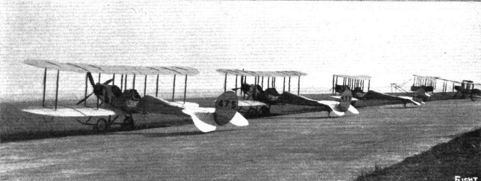
CENTRAL FLYING SCHOOL, UPAVON. - Some of the machines of C Flight.
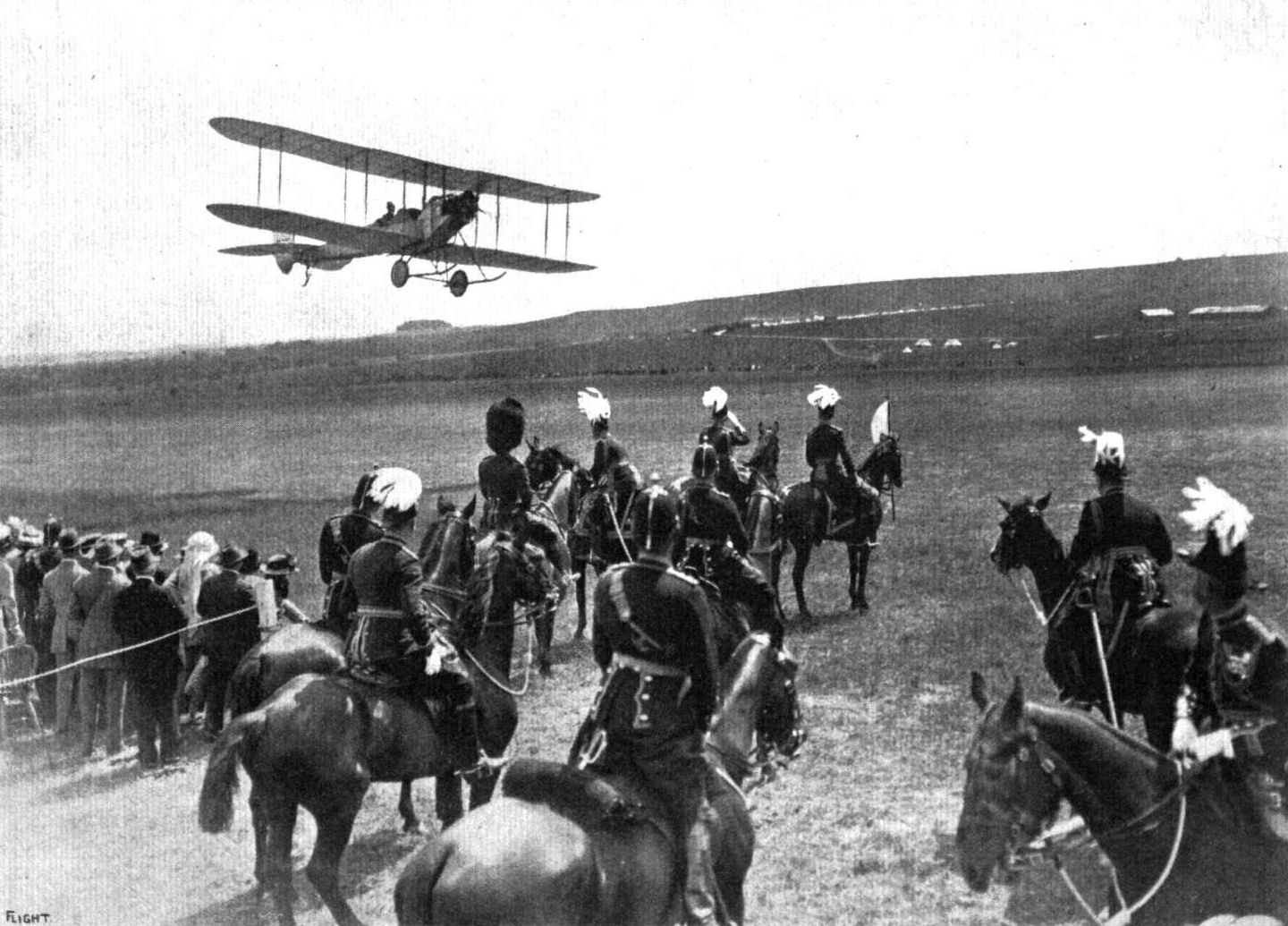
THE KING'S BIRTHDAY. - General Smith-Dorrien reviewing troops at Ludgershall. In our photograph the "fly past" of one of the aeroplanes is seen at the moment of dipping before the saluting base.
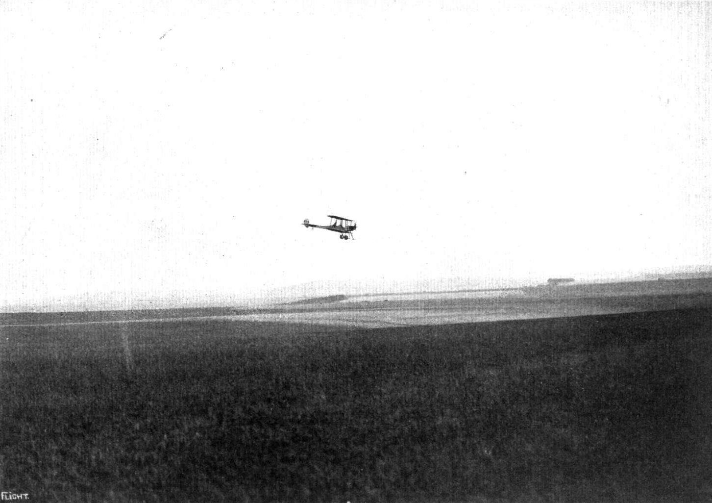
CENTRAL FLYING SCHOOL AT UPAVON. - A B.E.2a in flight over the gallops, with Netheravon in the distance.
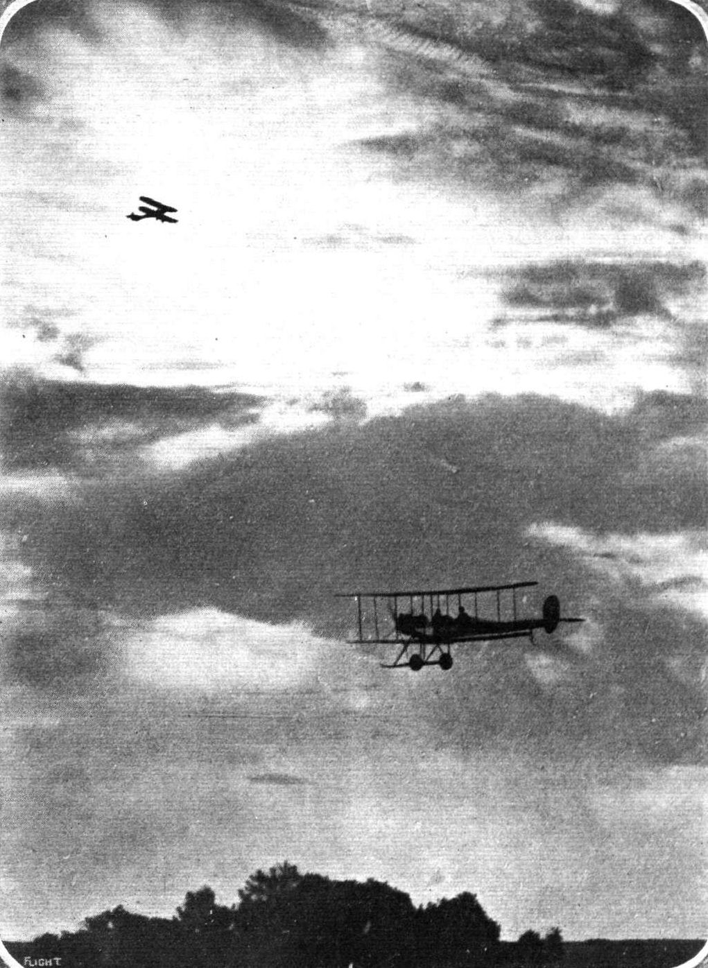
The start for the South of the R.F.C. No. 2 Squadron, Montrose, at 5.30 a.m.
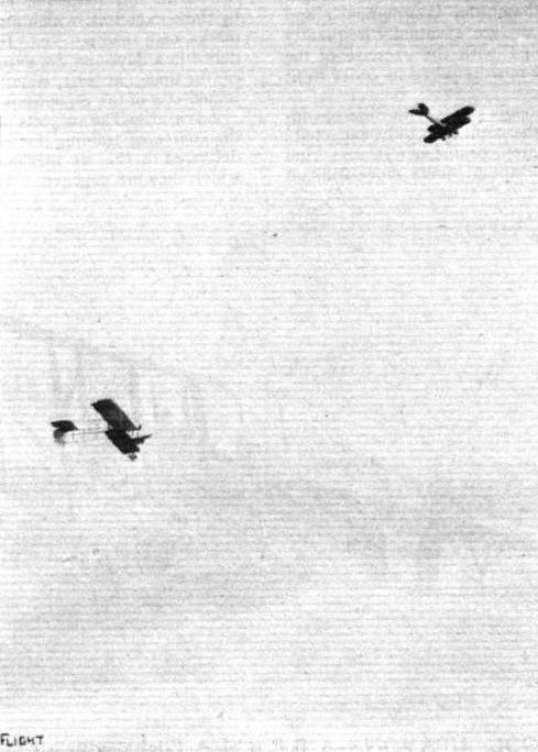
A B.E. and a Henry Farman flying at Upavon.
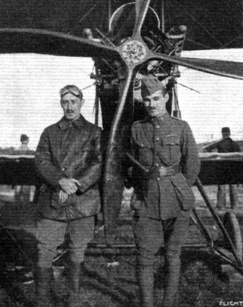
OUR FLIGHT OFFICERS AT THE FRONT. - Lieut. Lawrence, R.F.C., and Lieut. Wingfield Smith, R.F.C., with a B.E. at ---.
Fig. 2. - Sections of tail planes: A, Avro tail, 1910-11. B, Nieuport tail, 1910-11. C, B.E. tail, 1911. D, B.E. tail, 1912.
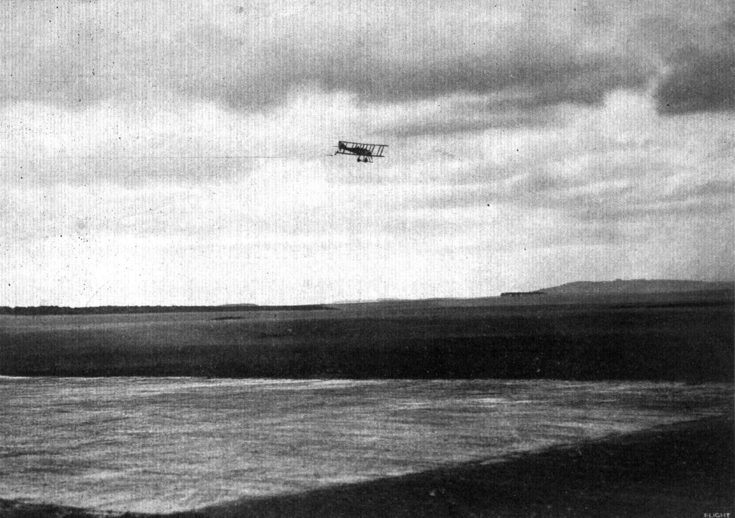
CENTRAL FLYING SCHOOL, UPAVON. - A B.E. 8 in flight during evening practice.
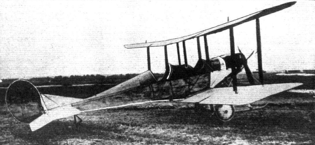
The Army aeroplane, R.E. 1 which was flown before the King and Queen, on Tuesday last, by Mr. E. T. Busk, with Major Clive Wigram as passenger. It was this machine that was referred to by Col. Seely at the Wright Memorial Banquet, and by Dr. Glazebrook in his lecture on Wednesday before the Aeronautical Society, on the "Development of the Aeroplane." In general appearance the R.E. 1 resembles the B.Es., and its stability is not due to any radical departures in design, but must be explained, we think, by careful scientific proportioning of surfaces and distribution of weights. From the accompanying photograph it will be seen that ailerons are fitted to both planes, presumably more in order to inspire confidence on the part of the pilot than because they are actually needed.

QUALIFYING FOR ROYAL AIR SERVICE AT HENDON. - An R.E. just about to make a flight.
Flight, November 6, 1914.
THE RYLEY BIPLANE GLIDER.
MR. L. G. RYLEY, of Coventry, sends us the following description and sketches of a biplane glider which he has built, and with which he hopes to make some interesting experiments shortly. Mr. Ryley informs us that although he is a member of the Coventry Aero Club, the glider is not built by the Club, but that he will be quite willing to allow members to indulge in flights on the machine:
"Gliding is a side of flight that is a little apt to be neglected at the present time, but it is a useful side nevertheless, and for the advanced model builder and others similarly interested it should be very attractive. There are a great many individuals who cannot afford to run a motor-driven machine, and to whom the flying of models lacks that co-operation between man and machine which is really what they require; to such therefore does the glider appeal. Just consider for a moment the points in its favour - practically most of the fascination of the motor-driven flight with all the charm of controlling a man-carrying aeroplane, and there is also that sense of mastery over the element which has so long defied conquest, added to the joyous exhilaration of the rush through the air, the delight of which has been compared to that of tobogganning. No doubt the chief problem in gliding is, to the town dweller especially, that of portability, and it was with a view to overcoming (to some extent) this obstacle that the writer constructed the machine shown in the accompanying scale drawings. The majority of model builders know how successful the 'canard ' type of machine is, and as the Wright glider was also successful, it was decided to adopt something similar (for the first machine, at any rate), rather than run the risk of constructing something which might prove a failure. Bamboo is used for the main spars, outrigger, and ribs, whilst for the skids ash is employed. The stanchions between the planes as well as the compression struts connecting the front and rear spars, are of selected red deal, and to all appearances seem quite strong enough for the job. The strut lug was described in FLIGHT, January 24th, 1914, whilst the remainder of the chief joints are shown in the diagrammatic sketches below. No doubt some readers will criticise the 'string and glue' joints, but it is really the only practical method of joining bamboo, and, if properly carried out, is quite strong enough; moreover, it enables several parts to 'give' slightly under certain circumstances, which otherwise might end in a broken spar. In the scale drawings a seat is shown, but after a few flights on the latter, I intend fitting a board and trying the prone position similar to the famous Wright Bros, early machines.
"This position will certainly cut down the resistance considerably, and the author would be glad to hear from readers who have tried it."
Flight, December 11, 1914.
THE RYLEY GLIDER.
By LESLIE G. RYLEY (Coventry Aero Club).
"DRAGON-FLY I" made its debut on Saturday, August 21st. Before describing the gliding capabilities of the machine the method of transport will perhaps be of interest to town readers who contemplate building a portable biplane glider in a "microscopic hangar." Rising at 6 a.m. we found the weather was very misty but by the time the various parts had been collected on to the writer's lawn - which had previously been cut and rolled to facilitate erection - the fog cleared sufficiently to enable us to start work. By 8.30 the various extensions were held in position by temporary wires, then came an interval. Three hours afterwards, the whole of the main planes were braced up, which, considering the number of struts and the fact that all the wires had to be cut off to length, as well as making some extra clips, was not a bad start. The elevator and its outrigger were then clipped along the planes as shown in the photograph. The next item on the programme was to get the glider out of the garden, which obstacle was surmounted by lifting the machine bodily over a 6-foot hedge. Four cycles were commandeered, and with the skids resting on the saddles we pushed the whole arrangement "end-on" up to the ground, where it was only necessary to push the outrigger into its sockets and connect up the elevator together with its wires. With regard to the flying some excellent towed flights were made both with and without a pilot, the wind being about 10 m.p.h., but owing to the field being rather small we were almost into the hedge before the machine lifted the writer, whose weight is over 10 stone. The latter's brother, a youngster of 7 years, had three excellent "joy rides" of about 80 yards in length, much to his enjoyment. Mr. Shorter, who, it will be remembered, recently constructed a cycloplane, made a good glide while lying down on the bottom plane. The only smash occurred when the above pilot was running in the plane, i.e., between the front and rear spars. This method was suggest by Mr. T. W. K. Clarke some years ago. Mr. Shorter not having much "leg-room" was hardly fast enough for the towers, and consequently when the machine lifted he jumped on to the trailing instead of the leading edge. The machine rose and landed "edge-on" with its elevator vertical. The pilot being unable to get out owing to the rear spar and diagonal wires dropped on a stanchion and broke it. This was the only damage sustained, although the machine landed rather heavily on several occasions - the low-built chassis holding up to the strain in an excellent manner, while the bottom plane and elevator had a good "cushioning" effect on the machine by compressing the air between themselves and the ground.

Mr. L. G. Ryley's glider, of which a description appeared in FLIGHT of November 6th. On the left is seen the glider at rest, where it will be noticed how the elevator and its outrigger are clipped along the planes in order to facilitate transport. On the right the "Dragon-fly" is just getting off. Mr. Ryley can be seen in the rear actuating the elevator by ropes.
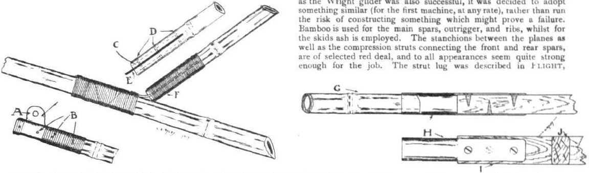
SOME CONSTRUCTIONAL DETAILS ON THE RYLEY GLIDER. - A. Sheet-steel fitting on which the elevator pivots. B. Steel pegs. C. Bamboo plugged and sawn down 3 Ins. D. One-sixteenth inch diameter steel pegs. E. Sheet steel. F. Bamboo bound with twine and glued. Right: A simple tube joint connecting elevator, outrigger and landing skid. G. Bamboo outrigger. H. Steel tube socket. I. Ash skid. J. Section of ash skid.
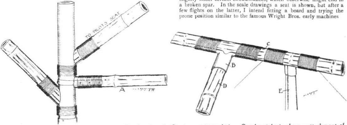
Left: Some sheet steel and twine joints in the chassis. A. Strut connecting skids. On the right is shown attachment of one of the elevator booms to upper front wing spar. B. Steel tube socket. C. Front spar. D. Detachable elevator boom.
E. Inter-plane strut.
E. Inter-plane strut.
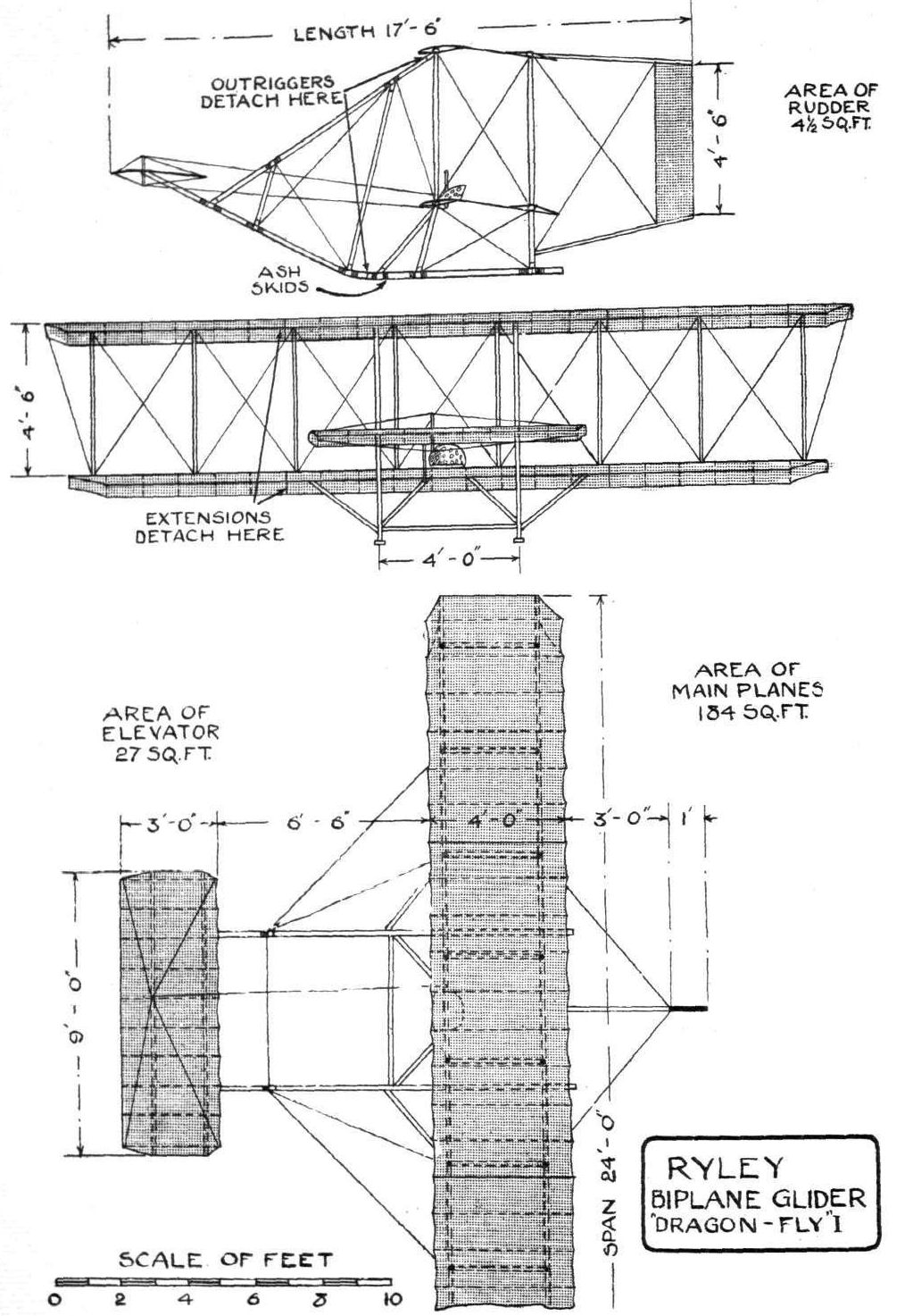
Ryley glider 'Dragonfly I'. Its use was curtailed bv the outbreak of war in 1914.
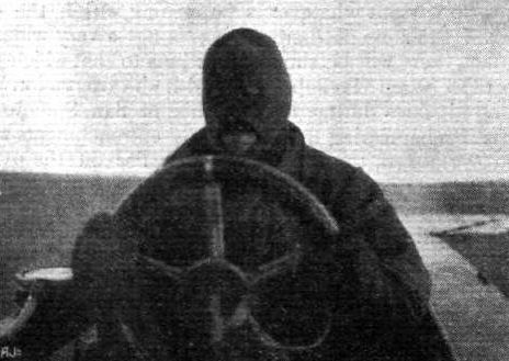
Major Gordon, R.F.C., N.W., flying Short 42 at the Leven Air Station. A snap from the passenger's seat at 2,000 ft.
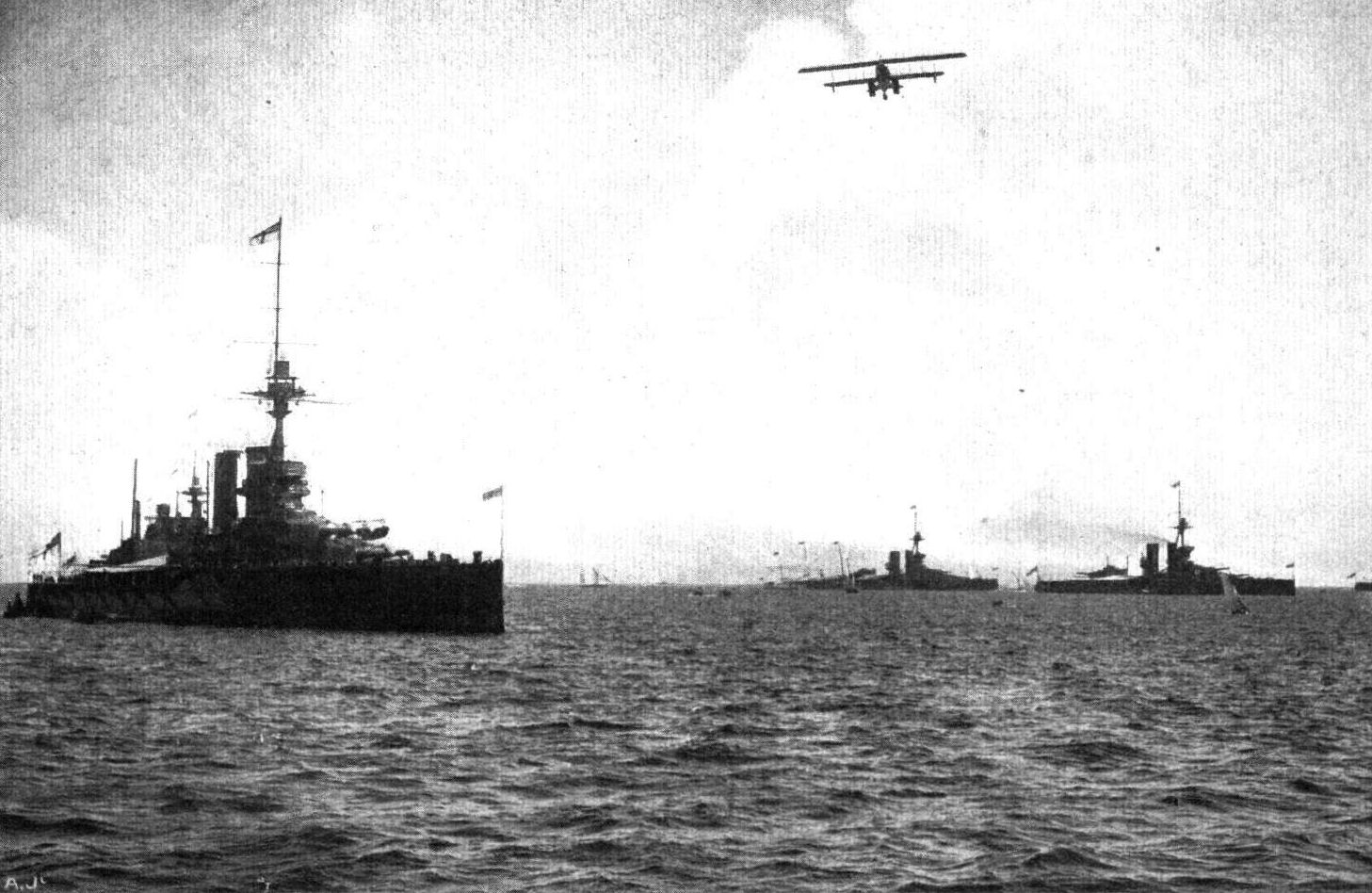
THE GREAT NAVAL REVIEW AT SPITHEAD. - Seaplane No. 77 flying over the super-Dreadnoughts "Iron Duke" and " Marlborough" (on right) and "Centurion" (on left).
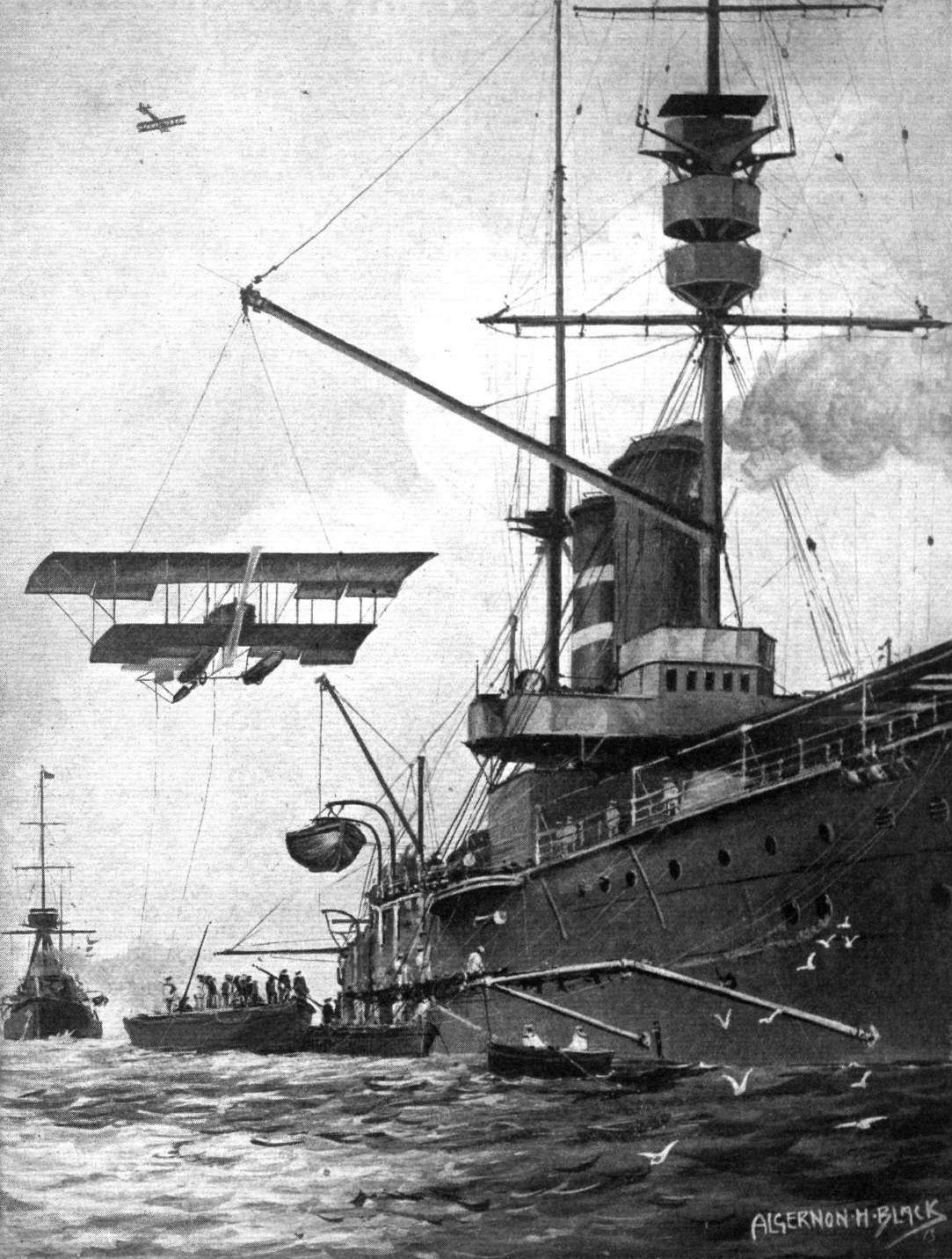
Hoisting a seaplane aboard H.M.S. "Hibernia."
Flight, January 10, 1914.
Mr. McClean Starts.
The first stage of Mr. F. K. McClean's trip up the Nile to Khartoum was made on Saturday last, when accompanied by two passeneers Mr. McClean piloted the 160 h.p. Short waterplane from Alexandria to Cairo, the distance of about 160 miles taking 2 hrs. 55 mins. Restarting from Cairo on Tuesday morning, with three passengers on board, the machine had to battle with the wind and eventually a stop was made at Minieh.
Flight, January 24, 1914.
Mr. Frank McCIean's Progress along the Nile.
ON the 16th inst. Mr. McClean arrived on his Short waterplane at Luxor, and later went on to Assuan, while two days later he made some nights to the delight of the great crowd which had gathered to see the machine. On Monday he started to continue his flight south to Khartoum, but after flying about 130 miles had to return to Assuan, owing to trouble with the motor. He has had very bad luck with his motor, and had to spend several days at Assiut on account of a broken ball race which distributed itself in the crankcase.
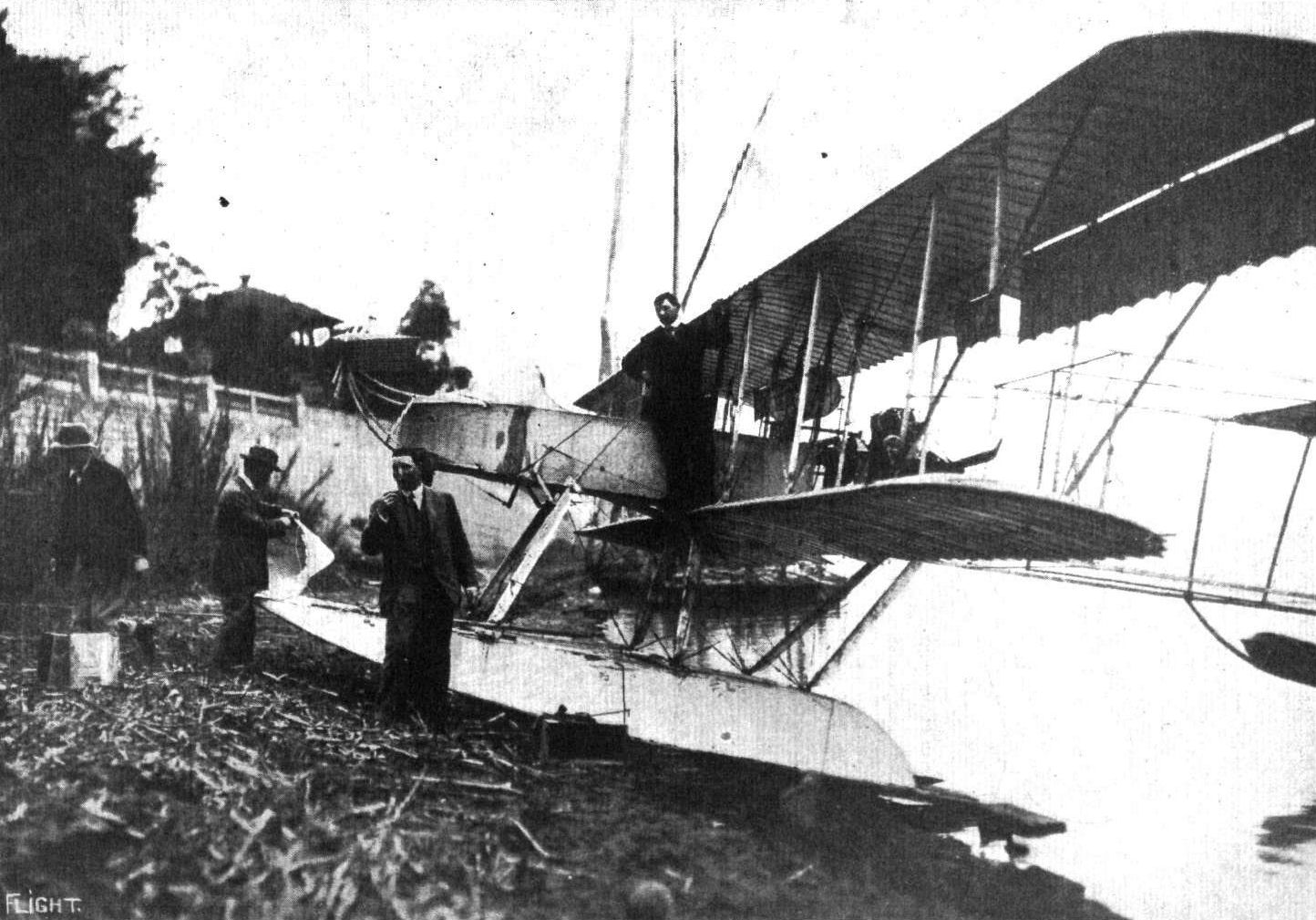
MR, FRANK McCLEAN AND HIS SHORT WATERPLANE AT CAIRO. - Mr. Frank McClean is seen standing on the ground in the centre of the picture without a hat on, the photograph being taken just prior to Mr. McClean's flight to Assiut.
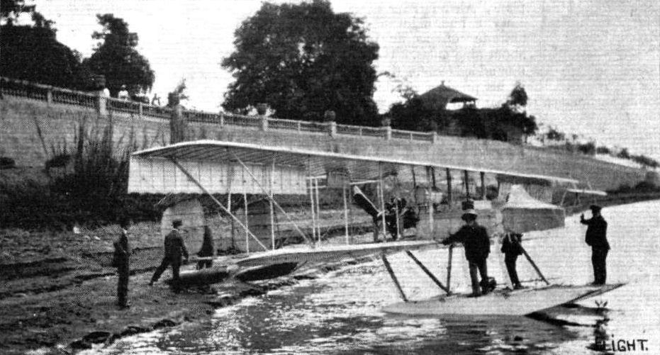
Another view of Mr. Frank McClean's Short waterplane on which he has been helping to make history on the Nile. Standing on the near float is Mr. Horace Short, the designer and constructor of the machine.
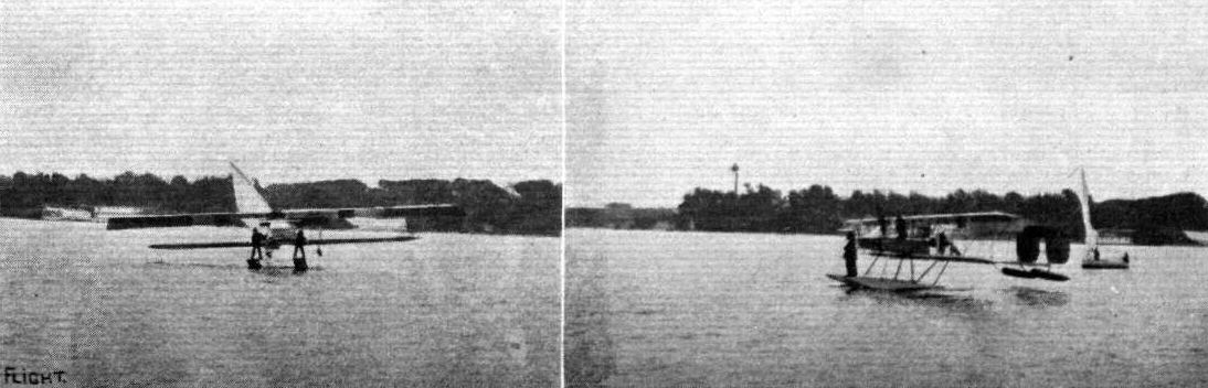
MR. FRANK McCLEAN IN EGYPT. - Banking on a sharp "taxi-turn" on the Nile on his 160 b.p. Gnome-engined Short waterplane.
Flight, March 14, 1914.
WHAT THERE WILL BE TO SEE AT OLYMPIA.
THE EXHIBITS.
Sopwith Aviation Co., Ltd. (44.)
OWING to press of work, and, in consequence, their inability to complete the second machine in time for the Show, this firm will only have one machine at Olympia - a two-seater bat boat of the Cusher type; a machine that somewhat resembles in appearance that built by Messrs. Sopwith for the Mortimer Singer Prize, but which is of more advanced design. We should have liked to have seen further examples of their workmanship and design, having in view their excellent record with both their land and sea machines, and we would especially recall the performance of the 100 h.p. Green-Sopwith hydro-aeroplane in the Circuit of Britain Race last August. But what they lack in quantity they have compensated for by quality, as the machine exhibited is one of the finest we have seen, and will be sure to attract considerable attention. The engine is a 200 h.p. 14-cyl. Salmson mounted upon the rear struts between the main planes, the radiator, which is of the honeycomb type, being placed on the front struts.
The whole machine will be of especially substantial construction, the boat being an extremely serviceable craft, and well provided with watertight compartments. The pilot and passenger sit side by side in a well in the centre of the boat. A wireless telegraphy outfit is fitted, driven by a Motosacoche engine, the whole of the apparatus being placed under cover immediately in front of the pilot. The machine is stated to be capable of climbing at the rate of 500 ft. per minute, and weighs 2,300 lbs. when empty, the useful load being about 1,000 lbs.
Flight, March 21, 1914.
THE OLYMPIA EXHIBITION.
THE EXHIBITS.
SOPWITH (THE SOPWITH AVIATION CO., LTD.). (44.)
THE 200 h.p. machine exhibited on this stand is a development of the bat-boat which won the Mortimer Singer prize, and of the later type which has recently been delivered to the Navy. It is one of the finest examples of workmanship at the Show, and is a thoroughly sound piece of work throughout. The boat itself, as well as the machine, was built at the Sopwith works at Kingston. The boat is built up of two skins of mahogany over ash stringers. It is of the single-stepped type, the hull being of the displacement type in front, gradually flattening out towards the step, where it is perfectly flat. The method of leading air to the step is very ingenious. Instead of doing this by leading tubes through the interior of the boat, which necessitates piercing of the bottom, the same results have been obtained by sheet brass channels screwed to the sides of the boat, as shown in one of the accompanying sketches.
The engine, a 200 h.p. Salmson, is mounted on pressed steel frames on very thick ash bearers, between the rear inner pair of the plane struts, whilst the radiator is mounted between the two front struts. The inter-plane struts are of ample size, and are all made of spruce, with the exception of the inner two rear struts which carry the engine bearers, and which have therefore been made of ash. The whole structure is further strengthened by two oblique struts running down to the forward portion of the boat.
The pilot's and passenger's seats are arranged side-by-side in an extremely roomy cockpit, the pilot occupying the right-hand seat. Control is by wheel on a single tube for ailerons and elevator, whilst the rudder is actuated by a pivoted foot-bar. A very complete set of instruments is mounted on a neat instrument board, in front of the pilot, whilst in the left-hand side of the boat, and in front of the passenger's seat, is mounted the wireless set driven by a motor cycle engine. The main petrol tank, which has a capacity sufficient for four and a half hours' flight, is situated in the boat behind the occupants. Petrol is forced from this tank to a smaller service tank between the engine and the radiator, whence it is fed by gravity to the engine. Under the pilot's and passenger's seats are carried two compressed air self-starters by means of which the engine may be started from the pilot's seat without the necessity of swinging the propeller, a performance which would be extremely difficult, it not actually impossible, on a machine of this type. The four tail booms form a V as seen in plan. These and their struts are made of spruce. The fixed tail plane is flat, and is braced by four steel tubes running from its outer edges to the lower tail boom. The elevator is divided in order to allow of sufficient movement of the rudder, which latter is of the balanced type. There is no vertical tail fin on this machine. It will be noticed that the lower main plane has a very pronounced dihedral angle, in order, no doubt, to allow the machine to roll considerably without fear of the lower planes touching the water, this being further prevented by wing-tip floats of similar construction to that of the boat.
<...>
Flight, August 21, 1914.
THE "ROUND BRITAIN" MACHINES.
THE machine which was officially numbered 3 for the Circuit of Britain was
The Sopwith Bat Boat,
to have been piloted by Mr. Pixton. In its general lay out this machine is very similar to the seaplane which was the object of so much admiration at the last Aero Show at Olympia. Several alterations have, however, been effected, as, for instance, the substitution of a 200 h.p. Sunbeam engine for the Salmson Canton-Unne with which the Show machine was fitted.
The wings have also been slightly raised in relation to the hull, so that the lower main plane, instead of resting directly on the gunwales of the boat, as it did in the previous machine, is mounted on short stout struts coming up from the interior of the boat. Joined to these are the four inner inter-plane struts carrying the bearers for the engine - a 200 h.p. Sunbeam of the Vee type - mounted slightly above the centre of the gap between the planes. Of these the upper plane is straight and has a considerable overhang, whilst the lower one is set at a very pronounced dihedral angle, partly, no doubt, to increase the lateral stability of the machine, and partly in order to provide sufficient clearance to allow the machine to roll considerably on the sea without danger of the lower planes touching. The lower planes are further protected by wing tip floats of the cylindrical type.
The inter-plane struts are of ample section, and are made of spruce, with the exception of the inner ones, which, as they take the weight of the engine, have been made of ash. When the machine is in the act of alighting, the weight of the machine is taken by two oblique struts running from the front end of the engine bearers to the forward portion of the boat. As in the Show machine the radiator is mounted between the inner front inter-plane struts.
The tail outrigger, which forms a V, as seen in plan, is made up of four booms of spruce connected vertically and horizontally by struts of the same material. Mounted on top of the upper tail-booms, in such a manner that its angle of incidence can be varied, is the fixed tail-plane, which has a flat under surface and a slightly cambered top. Hinged to the trailing edge of this stabilizing plane is the divided elevator, and pivoted round the rearmost upright strut in the tail outrigger is the rudder, which is of large area and balanced. It will be noticed that no fixed fin is incorporated in the tail unit, all the vertical surface aft being provided by the rudder. Cross-bracing everywhere between the main planes, as well as in the tail outrigger, is effected by means of stout stranded cables, and all control cables are in duplicate.
Interesting as the aeroplane portion of the machine undoubtedly is, the hull or boat is even more so, incorporating as it does all the improvements that long experience with this type of craft has suggested to the designers.
Although following fairly closely on the lines of the boat of the last Olympia Show machine, several details have undergone alteration and improvement, making the Sopwith Bat Boat one of the finest examples of sea worthy flying machines in this or any other country.
In the nose the boat is of the displacement type flattening out gradually towards the step, where it is of hydroplane form. Just behind the step the bottom of the rear portion of the boat is slightly V-shaped, running out to a flat bottom at the stern. Constructionally the boat is built up of two skins of mahogany laid on in opposite directions over a strong framework of ash stringers. The front part is provided with a curved deck, which will quickly shed any water that may wash over it. In front of the occupants' seats the deck is swept upwards to form a wind screen, which also serves to protect pilot and passenger from water spray when getting off or alighting in a rough sea. The high freeboard of the boat further helps to make this an all-weather craft.
One of the numerous difficulties which beset the designer of hulls or floats of the stepped type is that of admitting air to the step. In the Sopwith Bat Boat this difficulty has been overcome in a most ingenious way by fitting external channels or scoops, screwed to the sides of the boat, thus doing away with the necessity of piercing the bottom as in the case of internal air tubes. As to the efficiency of this arrangement, one can only conclude that it has proved to answer its purpose, since after being thoroughly tested in previous machines it has been retained in this latest product of the Sopwith firm.
From the accompanying illustrations a good idea may be formed of the spacious accommodation for pilot and passenger, whose seats are arranged side by side inside the extremely roomy cockpit, the pilot occupying the right-hand seat. Ailerons and elevator are operated by means of a rotatable hand-wheel mounted on a vertical tube which is free to move in a forward and backward direction. The rudder is actuated by a pivoted foot bar. Large petrol and oil tanks, the capacity of which are 70 galls, and 7 galls, respectively, or enough for a flight of five hours' duration without replenishments, are fitted. The weight of the machine empty is 2,300 lbs., and with full load, including pilot, passenger, and fuel for five hours, the weight is 3,120 lbs. As the total area is 600 sq. feet, the loading works out 5 lbs. per sq. foot. A speed range of from 48 m.p.h. to 75 m.p.h. is anticipated, so that with five hours' fuel the radius of action is in the neighbourhood of 180 miles. By fitting larger tanks it should be possible, if desired, to increase this figure considerably.
In the event of the Sopwith Bat Boat being, or having already been, taken over by the Admiralty, there is no doubt that she would not only prove an effective addition to our fleet of seaplanes, but that she would also add considerably to the high reputation of the Sopwith Company.
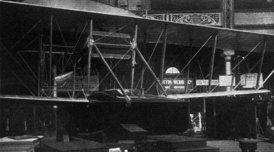
Three-quarter front view of the Sopwith bat boat.

A view of the Round Britain Sopwith Bat Boat.
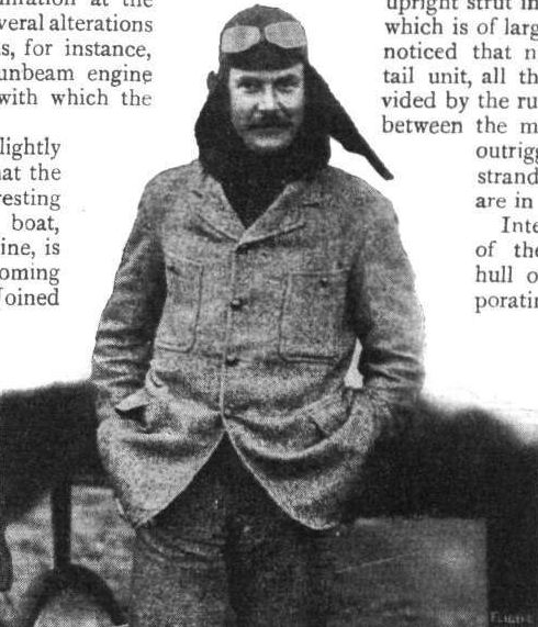
Mr. C. Howard Pixton, the pilot who was nominated for the Sopwith Bat Boat in the Round Britain Race.

The 200 h.p. Sopwith flying boat.
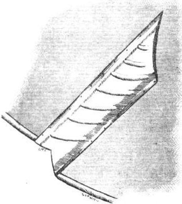
The brass channel which leads air to the step of the Sopwith bat boat.
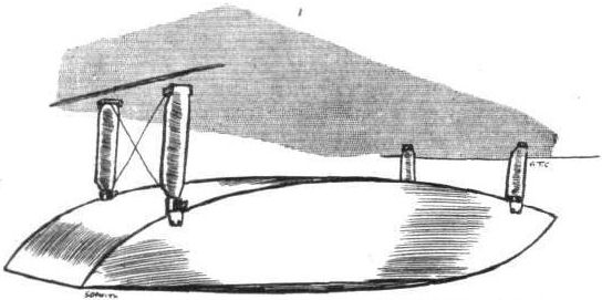
One of the wing-tip floats on the Sopwith bat boat.
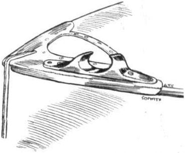
Streamline snatch-cleat on the bow of the Sopwith bat boat.
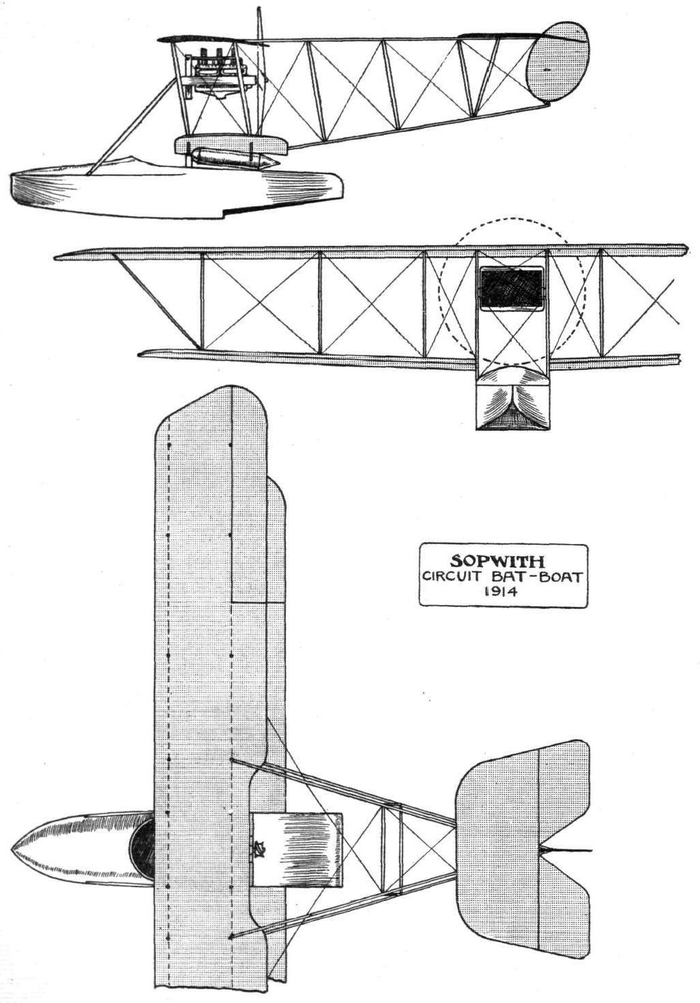
THE ROUND BRITAIN SOPWITH BAT BOAT. - Plan, front and side elevations.
Flight, March 21, 1914.
THE OLYMPIA EXHIBITION.
THE EXHIBITS.
SOPWITH (THE SOPWITH AVIATION CO., LTD.). (44.)
<...>
Unfortunately Sopwith's were prevented, by lack of space, from exhibiting more than the one machine, and have had to be content with showing one of the main floats of their tractor hydro. This float is of similar construction, although of a different shape, lo that of the boat. The workmanship in this float, as well as in that of the complete machine, is of the very highest quality. The float shown is of the single-step type, and has five watertight compartments, each fitted with a very neat inspection door. These, as will be seen from the accompanying sketch, have bevelled edges, and are screwed down with butterfly nuts, the opening in the deck being rubber faced in order to provide a watertight joint. The combined trolley and turntable on which this machine is mounted greatly facilitates the operation of running the machine from the hangar down to the water and vice versa, and would appear to be an absolutely necessary accessory for the easy handling ashore of so heavy a craft as this.
An item in the exhibit on this stand which attracts considerable attention is the actual Green engine used by Mr. Hawker in his waterplane flight round Britain last summer. This engine, it will be remembered, flew 1,043 miles in 55 3/4 hours, or actual flying time 21 hours and 44 mins., which is claimed to be a world's record.
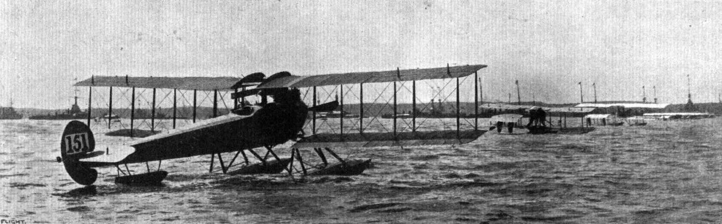
THE GREAT NAVAL REVIEW AT PORTSMOUTH. - A view of some of the Navy seaplanes at their moorings with the battleships at Spithead, awaiting the King's inspection.
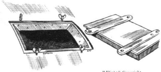
One of the inspection doors in the floats of the Sopwith tractor hydroplane.

The leaf spring, which provides the springing of the floats, on the Sopwith tractor seaplane.
Flight, May 22, 1914.
THE AERIAL DERBY.
THE PILOTS AND HOW TO RECOGNISE THE MACHINES.
No. 19. The 80 h.p. Sopwith
is a small fast machine, somewhat similar to the Vickers and Bristol, but has a wider and deeper fuselage, and may be identified by its chassis, which differs from that of the two above-mentioned machines in that two skids are fitted.
No. 20. The 100 h.p. Sopwith Biplane
is similar in outward appearance to No. 19, from which it differs only in engine power.
THE MACHINES AND HOW TO RECOGNISE THEM.
Nos. 19 and 20. The Sopwith Biplanes, of which one is fitted with an 80 h.p. engine, whilst the other has a 100 h.p. motor, are very similar to the biplane on which Mr. Pixton won the Schneider race at Monaco recently, with the exception, of course, that it is fitted with a land chassis. As these small Sopwith biplanes are very fast indeed, they should provide a very close race with some of the other really fast machines entered.
Flight, September 25, 1914.
THE R.N. AIR SERVICE RAID ON ZEPPELIN SHEDS.
IN the following statement issued by the Secretary of the Admiralty through the official Press Bureau, the story of the raid by the Royal Naval Air Service pilots on the Zeppelin sheds at Dusseldorf is briefly told. Dusseldorf is on the Rhine about 22 miles north of Cologne, and is about 103 miles from Antwerp. It, with Cologne (the headquarters) and Darmstadt, form the bases of Germany's third Airship Battalion. The statement is as follows :-
"Yesterday British aeroplanes of the Naval Wing delivered an attack on the Zeppelin sheds at Diisseldorf.
"The conditions were rendered very difficult by the misty weather, but Flight Lieutenant C. H. Collet dropped three bombs on the Zeppelin sheds, approaching within four hundred feet.
"The extent of the damage done is not known.
"Flight Lieutenant Collet's machine was struck by one projectile, but all the machines returned safely to their point of departure.
"The importance of this incident lies in the fact that it shows that in the event of further bombs being dropped into Antwerp or other Belgian towns measures of reprisal can certainly be adopted if desired to almost any extent."
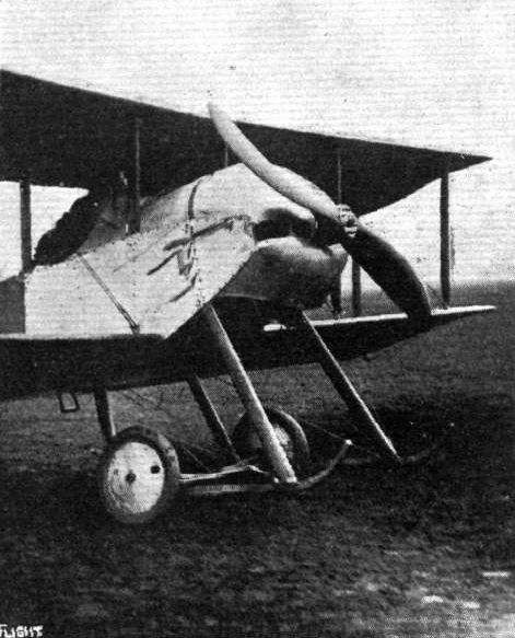
The landing chassis of the new Sopwith biplane at Brooklands.
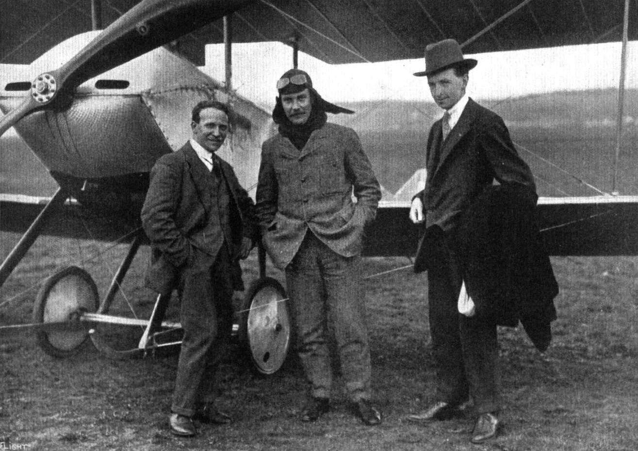
THE SCHNEIDER CUP VICTORY. - From right to left: Mr. T. O. M. Sopwith, the designer and builder of the winning seaplane; Mr. C. Howard Pixton, the pilot; and that important "accessory," the expert mechanician, Mr. Victor Mahl.

The Sopwith Scout (Nos. 19 and 20).
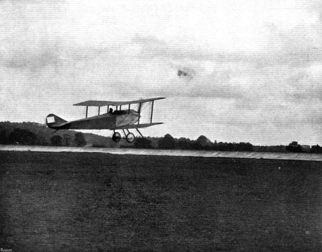
Mr. C. Howard Pixton on the Sopwith "tabloid"just getting off at Brooklands.

THE SOPWITH "TABLOID" A T BROOKLANDS. - Mr. Howard Pixton banking for a turn.
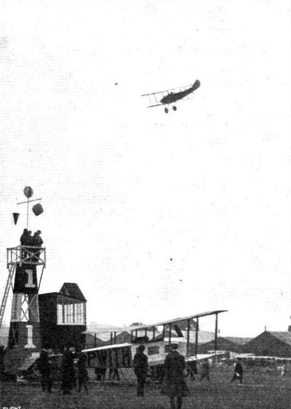
R. H. Barnwell, the scratch man and the last man to leave in the Aerial Derby, just off from Hendon Aerodrome on the Sopwith biplane on Saturday last.
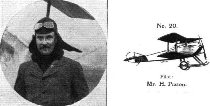
Pilot: Mr. H. Pixton.
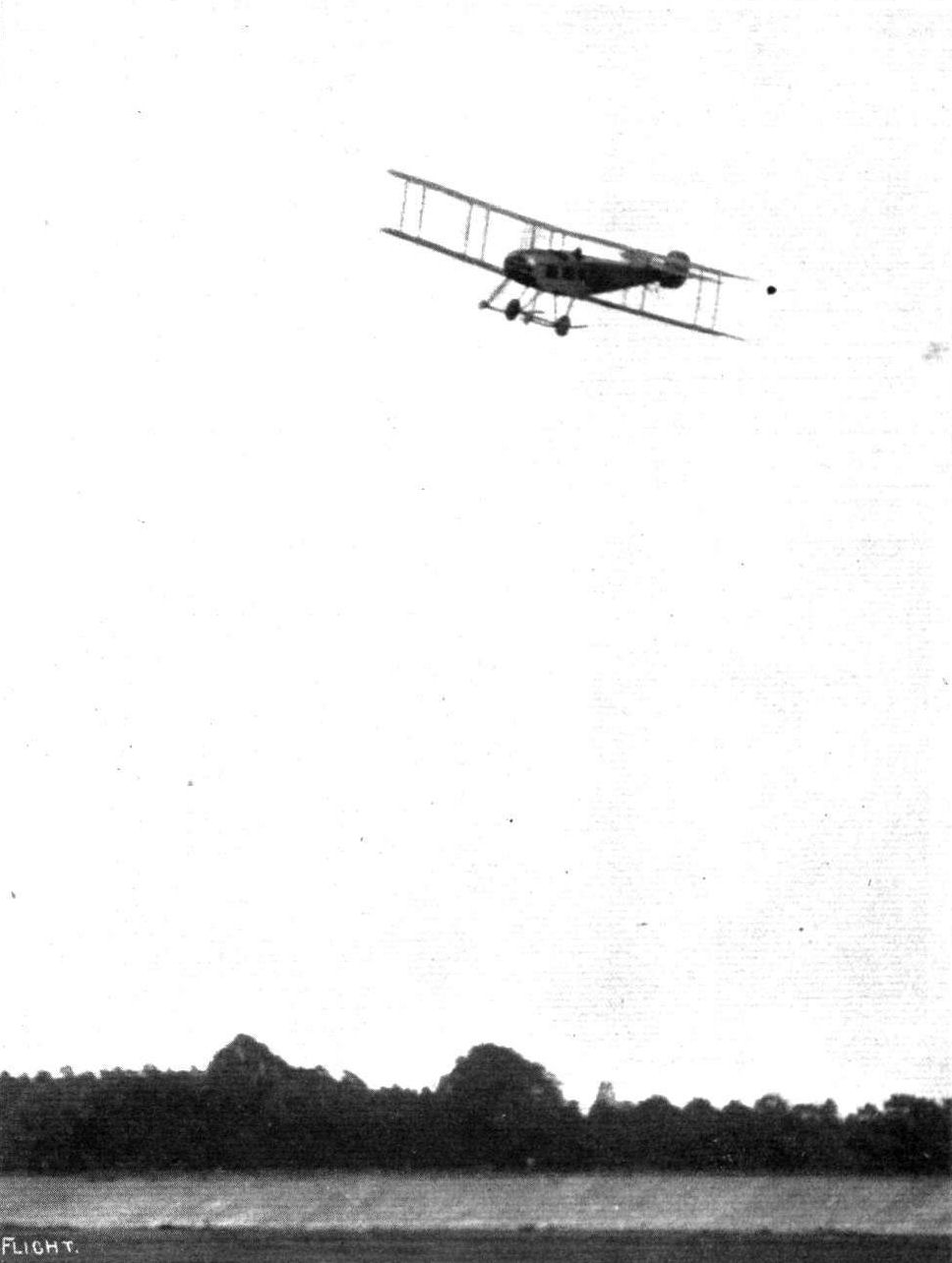
AT BROOKLANDS. - Mr. Hawker in flight on the Sopwlth Tractor during the past season.
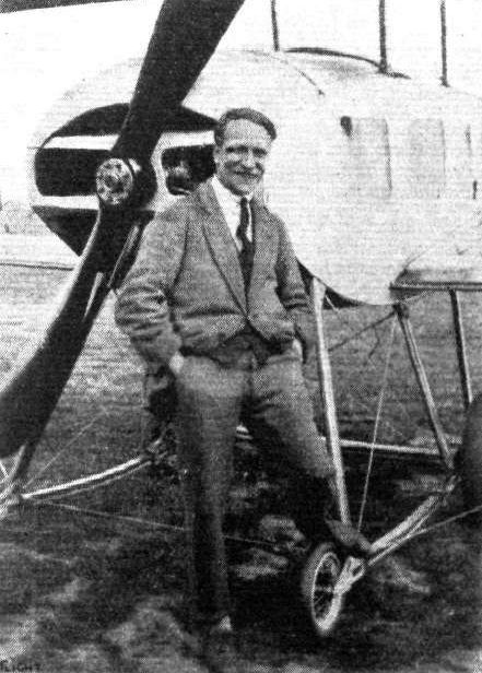
Mr. Victor Mahl, who has just secured his pilot's certificate on a Sopwith machine. It will be remembered Mr. Mahl was the mechanician who assisted Mr. Howard Pixton recently during his flight at Monaco in connection with the Schneider Cup, & c.

Lieut. Spencer Grey flying the new Sopwith biplane at Hendon. From an original drawing by Roderic Hill.
Flight, July 10, 1914.
EDDIES.
SOME details are to hand regarding the work of Capitaine de Freigate Collyns P. Pizey, who before his appointment to the Marine Royale Hellenique, was so well known to our readers from his connection with the Bristol Co. A very flattering report is given of the work of the Anzani-engined Sopwith "pusher" seaplane, which in one month was flying for some 40 odd hours. Five Greek officers have been trained on it, and they are now ready for solo flights. This is probably the first time that naval officers have been taught to fly directly from the sea without first doing land flying. The names of the first five officers to join the corps that Mr. Pizey is organising for the Greek Government are :- Lieut. Moriatinis, Lieut. Papageogin, Lieut. Panioton, War. Officer Meletopoulos and War. Officer Courbelis. The conditions under which the school is working are anything but favourable, as there are no sheds or shops, but in spite of that good progress is being made. Some time ago Mr. Pizey made several flights over the British fleet anchored in Phaleron Bay, and among the passengers taken up was Admiral Mark Kerr. In connection with his work Mr. Pizey has the assistance of four keen British "boys" - Lapray, Gaskell, Simms, and Radley - who rank as warrant-officer mechanics.

AVIATION IN GREECE. - On the left Mr Collyns P. Pizey in the Sopwith "pusher" seaplane with his first pupil, Lieut. Morlattnts. On the right, Mr. Pizey and Capt. Leigh, of the British Mission, and pilot of Farman schools.
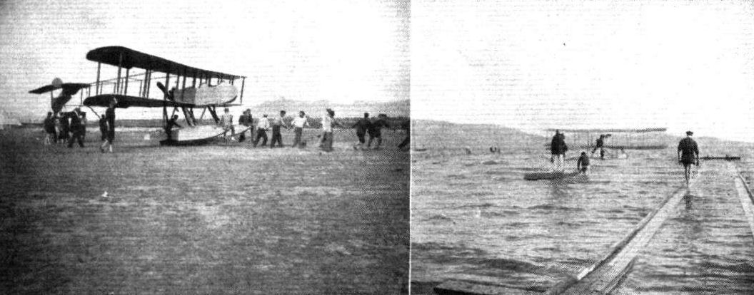
AVIATION IN GREECE. - On the left, bringing in the Anzani-engined Sopwith "pusher" seaplane at the Eleusis Air Station after morning flying by Mr. Collyns P. Pizey of the Royal Hellenic Marine Service. On the right Admiral Mark Kerr with Mr. Collyns P. Pizey, punting out on Astra float to the Sopwith seaplane. The man on the slipway is Lapray, one of Mr. Pizey's English "boys."
Flight, August 7, 1914.
THE "ROUND BRITAIN" MACHINES.
ALTHOUGH the Circuit of Britain for the Daily Mail prize, which was to have started from Southampton on Monday next, has naturally been indefinitely postponed by the Royal Aero Club on account of the calamity of war in which this country has been involved, the work and money expended by the manufacturers on the various machines are not by any means wasted, since it seems likely that they will be called upon to show their capabilities in actual service instead of in a peaceful race round our coasts. As the nine entries may be said to represent fairly closely the present trend of our seaplane industry, we think that our readers will agree that descriptions of these nine types of seaplanes will be of great interest. We therefore intend to publish in the present and successive issues articles dealing with the construction of these nine "Circuit" machines, dealing with them in the order of their official numbers in the race. As a number of the machines are, at the time of going to press, still in the shops in a more or less unfinished state, it has been impossible to obtain photographs of all of them, and we have therefore had perspective sketches prepared, from which those of our readers who are not experts in "reading" scale drawings may obtain a good idea of the general arrangements of the machines. In addition to these sketches we are giving drawings either to scale, or in some cases as nearly as possible to scale, and in the present issue will be found a table of the chief characteristics of all the machines, which should prove useful for purposes of comparison.
The machine which was officially numbered 1 is:
The Sopwith Tractor Biplane.
Our readers are already familiar with previous Sopwith machines of the tractor type through illustrated descriptions in FLIGHT, and the Circuit biplane does not differ materially from its prototypes except in dimensions. From the accompanying illustrations it will be seen that the fuselage is slightly more elongated than is usual in the Sopwith Scouts, probably in order to counteract to a certain extent the side area of the floats. Since the machine was flown as a land aeroplane at Brooklands the size of both rudder and tail fin has been increased, so that the vertical surface aft now seems quite capable of taking care of the side area of the two floats, and the nose of the covered-in fuselage. This member, which is of rectangular section topped by a turtle back, is built up in the usual way of four ash longerons, struts, cross-members, and diagonal bracing. At the rear the fuselage terminates in a vertical knife-edge, whilst in the nose of the machine the longerons of the fuselage converge to join the front engine bearer, which forms a horizontal knife-edge. The aluminium cowl over the engine is of the same type as that fitted on the small scouting biplanes, a type which has been found in practice to combine a good entry for the air with sufficient cooling of the engine.
In front, the fuselage is wide enough to accommodate the motor - a 100 h.p. Gnome monosoupape - which is mounted between double bearers, and drives directly a propeller of 8 ft. 6 ins. diameter.
Immediately behind the engine is situated the petrol and oil tanks, whilst an additional supply of petrol is carried in another tank behind the passenger's seat. This is situated sufficiently far forward to provide a good view in a downward direction, whilst from the pilot's seat, placed as it is in line with the trailing edge of the lower plane, which has been cut away near the body, an excellent view is obtained in a downward and forward direction. By cutting away the trailing edge of the centre portion of the upper plane, the pilot is enabled to look upwards and forwards, so that it would appear that the arrangement of the pilot's seat and the staggered planes is such as to give the pilot, as nearly as possible in a machine of this type, an unrestricted view in all directions.
The main planes are of the usual Sopwith type, and are very strongly built. Compression struts are fitted between the main spars in order to relieve the ribs of the strain of the internal cross-bracing. Ailerons are fitted to the tips of both upper and lower main planes, and are slightly wider than the remaining trailing portion of the wings in order to render them more efficient. The ailerons are operated through stranded cables passing round a drum on the control lever in front of the pilot's seat. The tail planes are of the usual characteristic Sopwith type, consisting of an approximately semi-circular tail plane, to the trailing edge of which is hinged a divided elevator. The rudder is of ample size, and a comparatively large vertical tail fin runs from the rudder post down to the leading edge of the fixed tail plane. The chassis is of a substantial type, and the two main floats are sprung by means of leaf springs interposed between the rear of the float and the rear chassis struts, whilst the floats pivot round their attachment to the lower end of the front chassis struts. The floats are spaced a comparatively great distance apart, in order to render the machine more stable on the water. A tail float of the usual type takes the weight of the tail planes when the machine is at rest.

THE COUPE SCHNEIDER. - The winning Sopwith seaplane, with Mr. Howard Pixton piloting, just rising off tne water at Monaco.

A snap of M. C. Howard Pixton flying the Sopwith seaplane at Monaco during his sucessful flight for the Schneider Cup.

A remarkable photograph secured by Mons. E. Marchessaux at Monaco on April 20th, during the final contest for the Schneider Aviation Cup. - This negative absolutely untouched, and shows Mr. Howard Pixton's Sopwith machine passing the Franco-British seaplane piloted by M. Burri. The above is one of the autograph photographs of the amateur photographer which he presented to the two pilots who finished for this cup.
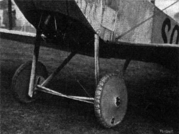
The special racing chassis fitted on the Sopwlth Scout flown by Mr. Barnwell in the Aerial Derby.
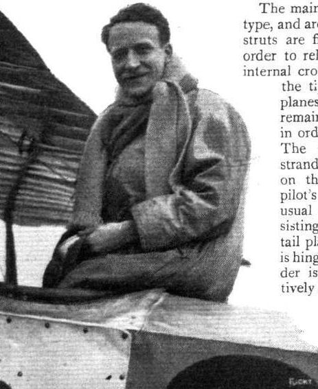
Victor MabI, the nominated pilot for the Sopwith tractor.

ROUND BRITAIN MACHINES. - No. 1. The Sopwith tractor biplane.
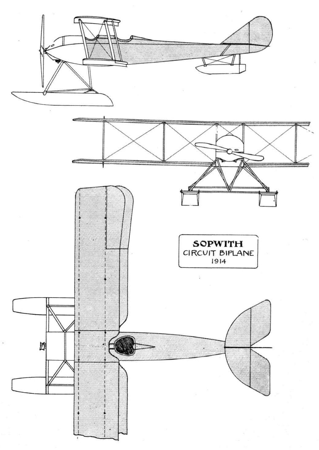
Flight, March 14, 1914.
WHAT THERE WILL BE TO SEE AT OLYMPIA.
THE EXHIBITS.
Vickers (Vickers, Ltd.). (66.)
THERE will be two machines exhibited by Messrs. Vickers on their stand, one of which will be a two-seater fighting biplane with the engine and propeller to the rear of the wings, while the other will be a tractor biplane. The former will be constructed of steel practically throughout, as the main spars, fuselage and landing chassis are made of that material, and only the ribs and skids are manufactured from wood, as was the case with the fighting machine shown last year. This machine will have a Maxim gun fitted in the front, the gunner occupying the front seat and the pilot the rear. Various improvements have, however, been made in the design of this machine, and these we shall deal with fully in subsequent numbers of FLIGHT.
<...>
Flight, March 21, 1914.
THE OLYMPIA EXHIBITION.
THE EXHIBITS.
VICKERS (VICKERS, LTD.). (66.)
Two machines are exhibited on the Vickers stand - one a 100 h.p. fighting "pusher" biplane, whilst the other is a fast scouting tractor biplane. The 100 h.p. Fighting Biplane is of a somewhat similar type to the one exhibited at Olympia last year, with the exception that this machine has not staggered planes. It is driven by a 100 h.p. Gnome monosoupape engine, mounted on overhung bearings in the rear of the nacelle. The latter structure is made throughout of steel tubes covered with aluminium. In the nose of the nacelle, and mounted on a universal joint resting on the tubular framework, is a Vickers Automatic K.C. gun, which has a range of action of 30 degrees in any direction from the line of flight. The gun projects through a circular opening in the nose of the nacelle, whilst a hemispherical shield is mounted on and moves with the gun barrel. This shield is fitted with mica windows, through which the gunner obtains his sights. This arrangement enables the gunner to operate the gun without the draught of wind interfering with the sighting of it. The seats, which are of the bucket type, are arranged tandem fashion, the passenger, of course, occupying the front seat. The pilot controls the machine by means of a wheel mounted on a tubular bridge of inverted U-shape. Rotation of the wheel operates the ailerons, whilst a to-and-fro movement actuates the elevator. The rudder is worked by a pivoted foot-bar.
The chassis is of a different type to last year's model. It consists of two ash skids, carried on four streamline steel tube struts. A tubular axle, streamlined with wood, is slung from the skids by rubber cord. This machine is built of steel practically throughout, with the exception of the wings, which have spars of I-section spruce, with ribs built up of three-ply webs and ash flanges. The lower plane is attached to the nacelle by fitting the spars into steel tube sockets running right across the nacelle. Streamlined steel tube struts separate the main planes, the whole being made rigid by means of stranded cables which are all in duplicate. The angle of incidence is 440, and the planes are set at a dihedral angle of 1°.
<...>
Flight, June 26, 1914.
EDDIES.
BROOKLANDS was the scene, on Saturday last, of great activity, though of a different kind from that which usually takes place there. Posters along the footpath from Weybridge station to the entrance gates announced a Red Cross Field Day, and a Red Cross Field Day it was. The slopes around the paddock and test hill were covered with Red Cross hospitals and tents, whilst Territorial troops livened things up by conducting a fierce "battle." It was amusing to watch a division of the defending Army scramble up the steep parts of the race track, the surface of which was obviously not designed for this sort of exercise, the majority of the "Terriers" evidently not having taken the precaution of fitting "non-skids." Ultimately, however, the top of the track was reached and from here a deadly hail of wax bullets were rained down on an imaginary enemy.
Mr. Barnwell, on the Vickers gun-carrying biplane, went out over the surrounding country to locate the enemy, and his passenger did his level best to kill off as many of the "invaders" as possible with the machine gun which was mounted in the nose of the nacelle. Later Barnwell must have regretted his part of the manslaughter for he went out again to look for "wounded," and after locating them brought back information as to their whereabouts, and thus probably saved many lives by enabling the field ambulance to render prompt assistance. Among the large and distinguished company which watched the proceedings during the afternoon were H.M. Queen Alexandra and the Dowager Empress of Russia, this being the first visit of a member of the British Royal Family to the track. Numerous flights were also made during the afternoon by Messrs. Mahl, Gower, Wilberforce, and several other pilots. In the evening Hawker arrived from Hendon, and delighted everybody by looping in excellent style.
The Vickers gun-carrying biplane.
Nose of Vickers gun-carrying biplane.

Sketch showing attachment of pulley for aileron cable employed on Vickers biplanes.
Nose of Vlckers gun-carrying biplane.
The 100 h.p. Vickers biplane.
Flight, July 10, 1914.
THE NEW VICKERS GUN-CARRYING BIPLANE.
A NEW Vickers biplane of the gun-carrying type made its initial appearance at Brooklands last week under weather conditions which were anything but favourable. When Mr. Barnwell took the machine out there was a strong wind blowing, and matters were not improved by the heat eddies set up by the glaring sun. In spite of these disadvantages, however, the machine behaved excellently, and appeared to be well balanced both longitudinally and laterally, Mr. Barnwell commencing to do right- and left-hand turns after once having got the "feel" of the machine. On subsequent flights the engine was switched off in order to test the gliding angle, which appeared to be exceptionally good.
A good idea of the general arrangement of the machine may be gained from the accompanying photographs. The nacelle, it will be seen, is comparatively shallow at the nose, thus greatly reducing the side area in front, whilst the rear vertical surface, formed by the rudder and fixed fin, is of ample proportions, so that there is little doubt that the machine will prove to be spirally stable. The main planes - of which the upper one has a considerable overhang with the weight taken by cables running over king posts - are separated by six pairs of struts. With the exception of the four inner struts, made of steel tubes, which pass through the nacelle, all the inter-plane struts as well as the struts in the tail outrigger are of wood.
Four steel tubes, forming a V, as seen in plan, carry the tail planes, and practically all the cross bracing is effected by stranded cable in preference to piano wire. The engine fitted is a 100 h.p. Gnome monosoupape driving a Vickers propeller. In its constructional details such as clips and sockets the machine incorporates a number of highly ingenious ideas, and the workmanship throughout the machine is of very high quality.
Flight, July 31, 1914.
EDDIES.
A new Vickers gun-carrying biplane made its first appearance at Brooklands last week. Mr. Barnwell had flown the older machine, which was described in FLIGHT a short time ago, over to the works at Joyce Green, and later returned on the new biplane, which had just left the stocks. In its general appearance the latest gun-carrier is a replica of the previous one, but several details have been altered. Head resistance has been reduced, wherever possible, as for instance in the arrangement of the control cables. The rudder and elevator cables pass along the tail booms in the usual way, but are then taken round pulleys and run parallel with the bracing cables of the inner bay of the main planes, whilst the aileron cables are taken through fair leads on the leading edge of the lower plane. Instead of the rotatable hand-wheel with which the previous machine was fitted, a single central lever actuates the ailerons. The bracing wires in the tail outrigger have been replaced by stranded cables, probably with a view to eliminate, as far as possible, any danger of breakage and consequent possibility of them getting entangled in the propeller. Constructionally, the machine is a beautiful piece of work, both as regards workmanship and finish, and aerodynamically it appears to be very efficient. Under the clever piloting of Mr. Barnwell, the new gun-carrier flies exceedingly well, and although it is comparatively new it has already been put through all manner of tests. The first day this machine was in the air Mr. Barnwell, on his arrival at Brooklands, did some fancy flying before coming down, including spirals and most alarming banks, that is to say, banks which would have been alarming had the pilot been less experienced.

Side view of the new Vickers gun-carrying biplane.
Flight, March 14, 1914.
WHAT THERE WILL BE TO SEE AT OLYMPIA.
THE EXHIBITS.
Vickers (Vickers, Ltd.). (66.)
THERE will be two machines exhibited by Messrs. Vickers on their stand, one of which will be a two-seater fighting biplane with the engine and propeller to the rear of the wings, while the other will be a tractor biplane.
<...>
The tractor machine has a fuselage and main spars of wood, but the landing chassis is built of steel and is a very simple Vickers type, the wheels being suspended on rubber cord. It will be observed that a very wide speed range is claimed for this machine - from 100 to 45 miles per hour - and we shall look forward with interest for information regarding its performance. The wings on this machine are staggered. Both machines will be well up to the usual standard of excellence and finish found in the work turned out by this eminent firm of constructors.
On the fame stand various sizes of Vickers-Levasseur propellers will also be shown.
Flight, March 21, 1914.
THE OLYMPIA EXHIBITION.
THE EXHIBITS.
VICKERS (VICKERS, LTD.). (66.)
Two machines are exhibited on the Vickers stand - one a 100 h.p. fighting "pusher" biplane, whilst the other is a fast scouting tractor biplane.
<...>
The 100 h.p. Tractor Scouting Machine, similarly to the fighting biplane, is driven by a 100 h.p. Gnome monosoupape engine mounted on overhung bearings. This machine, which it is anticipated will prove very fast, is at present fitted with a comparatively small tank, which has a capacity sufficient for two hours' flight only, with pilot and passenger; but another tank, so designed that it can be fitted very quickly, may be carried instead of the passenger, which gives a capacity sufficient for 4 1/2 hours' flight. The fuselage of this machine is built up in the usual way of ash longerons, and ash and spruce struts and cross-members. The pilot's and passenger's seats are arranged in tandem with the pilot in the rear, and control is by means of a single, central column and a foot-bar. The usual set of instruments is carried on the dashboard in front of the pilot. The tail planes consist of a cambered fixed stabilisng plane, semicircular in plan view, to the trailing edge of which is hinged a divided elevator. The rudder is balanced, and no vertical fin is fitted. A tail skid sprung by rubber shock-absorbers inside the fuselage protects the tail planes against contact with the ground.
The chassis is of a very simple type, consisting of two pairs of V streamlined steel tube struts. In the V between the struts is earned the tubular axle, which is sprung by means of rubber cord. The angle of incidence on this machine is only 3°, and as the planes are absolutely flat on their lower surface, it should prove very fast indeed. The main planes are set at a slight dihedral angle, 1° to be exact.
In addition to the two complete machines, there are shown on this stand several examples of the Vickers-Levasseur propellers in various stages of construction.
Flight, May 22, 1914.
THE AERIAL DERBY.
THE PILOTS AND HOW TO RECOGNISE THE MACHINES.
No. 15. The 100 h.p. Vickers Biplane
is a small, fast tractor machine which will be a little difficult to distinguish from the Bristol machine No. 18. However, it has a considerably deeper and wider fuselage than has the Bristol.
THE MACHINES AND HOW TO RECOGNISE THEM.
No. 15 The 100 h.p. Vickers Biplane was also exhibited at the last Olympia Aero Show, and belongs to the small fast scouting type tractor biplane class. As this machine has not been flown in public up to the time of going to press, the speed is not known, but it is anticipated that the machine will prove very fast indeed.
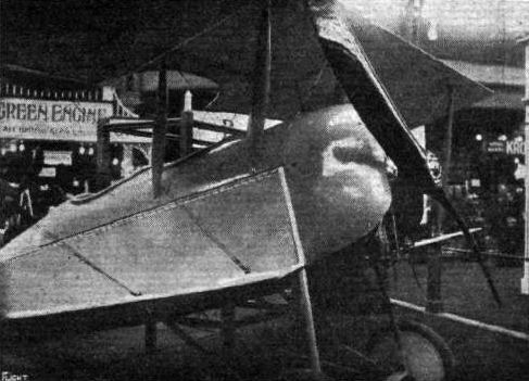
The Vickers tractor biplane.
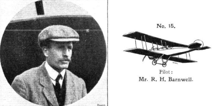
Pilot: Mr. R. H. Barnwell.
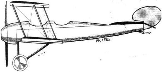
The 100 h.p. Vickers tractor biplane.
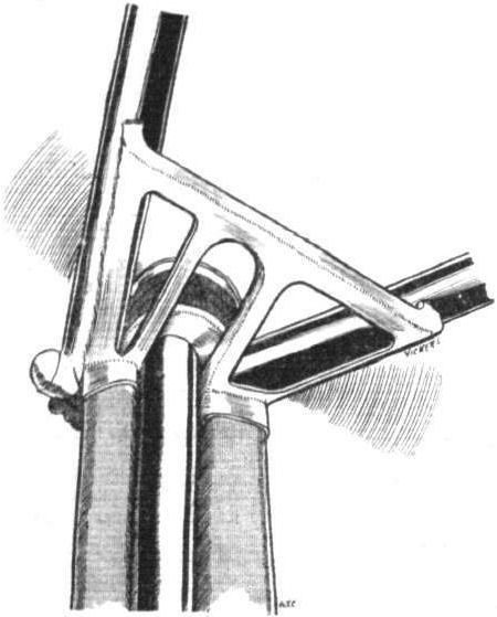
Chassis detail of Vickers tractor.

Mounting of altimeter on Vlckers tractor.
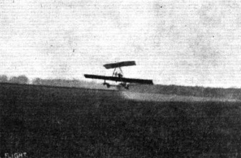
Watson No. 2, 1912, showing balancing plane in operation.
Flight, May 15, 1914.
THE WATSON ROCKING-WING AEROPLANE.
IN connection with the competition organised by "L'Union pour La Securite en Aeroplanes," Mr. P. A. Watson, of Dundee, who has been experimenting with rocking-wing aeroplanes for a number of years, is at present demonstrating his latest type machine (No. 3) at Buc. We have asked Mr. Watson for a description of his machine, and he has sent us a copy of the explanation which, in accordance with the rules of the competition, he has given l'Union. The following extract from Mr. Watson's explanation of the principles of his machine will, we think, make it clear in what respect his aeroplane and the manner in which it is controlled differ from ordinary types.
The machine (No. 3), as will be seen from the accompanying photographs, is of the tractor type, and is driven by a 40 h.p. Anzani engine, mounted in front of the wicker-work nacelle. The chassis, which is of the four-wheeled type, is very robust and provides a comparatively wide track. An outrigger formed by two tail booms carries at the rear a monoplane elevator and a small fixed vertical fin. It will be observed that no movable vertical rudder is fitted. Mounted on a very strong cabane formed by two pairs of inverted V struts, is the balancing plane, by means of which lateral equilibrium is maintained, and the action of which is explained by Mr. Watson in the following extract:-
"The method of preserving lateral equilibrium invented by the Wright brothers has been slavishly followed, but this has probably been due to the fact that these gentlemen were the first to fly in a practical way. This does not prove, however, that they have not misled everybody as to the best means of preserving lateral equilibrium. It must be remembered that they began their experiments at Kittyhawk with the fixed intention of preserving lateral equilibrium by warping the wings, and when this means alone was found insufficient they never considered the possibility of using other means than warping, but looked for an addition to their warping wing machine and devised the vertically pivoted tail.
"The Wright Brothers have stated, and it is well known, that if the angle of incidence of the lower wing is increased, its resistance is also increased, so that the fore and aft axis of the machine turns about its vertical axis, away from the line of flight, and the lower wing loses its velocity, unless this is prevented by the movement of a vertically pivoted tail. In the absence of a vertically pivoted tail the loss of velocity of the wing whose angle of incidence is increased, causes it to lose its support, and it descends while the other rises. Thus the vertically pivoted tail is proved to be necessary if lateral equilibrium is to be preserved by the warping of the wings. The absence in a bird of the vertically pivoted tail proves that warping of the wings is not the method employed by a bird to preserve lateral equilibrium.
"The method by which a bird preserves its lateral equilibrium, and steers to right or left, is a beautiful method of flight. If a soaring bird is making a straight flight with its wings transversely in the horizontal and it wishes to steer to one side, it rocks its wings about a fore and aft axis by pulling one wing down and allowing the other to rise. It is able to do this because the centre of gravity of a bird is below its centre of support, and a pendulum thus exists. The force which this pendulum exerts if shifted from the natural position in which it hangs, provides a fulcrum in mid-air from which the wings can be rocked. Since the mass of the pendulum is considerable its inertia also helps in providing a fulcrum. When the wings are rocked out of the horizontal their lift has a component force pulling to one side of the line of flight. Now, when a body which is moving in a straight line is acted on by a constant force at right angles thereto, the body describes a circle. Therefore when the bird has rocked its wings it describes a circle.
"It must be remembered that this beautifully balanced flight takes place without any attention on the part of the bird except that it controls the elevation (according to whether it wishes to ascend or descend or fly horizontally during the turn) and rocks its wings to that extent which it considers necessary to make a circle of the desired diameter. In fact the bird possesses a method of flight which takes care of itself and is controlled by two movements. The difficulty which caused Wilbur and Orville Wright to abandon this beautiful method of flight adopted by the bird was that considerable power is required to rock the whole surface of the wings in the manner of the bird.
"A soaring bird has sufficient power to rock the whole wing surface quickly, since it employs for this purpose its strong flying muscles, but the pilot of an aeroplane has not sufficient power for this purpose. Thus the Wright brothers abandoned the perfect method of flight of the bird in favour of warping wings and a vertically pivoted tail, because with this latter method the pilot can preserve lateral equilibrium without having to exert so much power. Less power is required to warp or to control the ailerons than to rock the whole wing surface in the manner of a bird. The choice between one or the other of these methods of preserving lateral equilibrium is a choice between the perfect flight of the bird, which, however, has the disadvantage of requiring considerable power on the part of the pilot, and the method of preserving lateral equilibrium by controlling the angle of incidence of the wing tips, or the angle of incidence of the supplementary surfaces, a method which has the advantage of requiring small power on the part of the pilot, but which causes an excess of resistance on the surface which has the greater angle of incidence, and thus necessitates the vertically pivoted tail with its consequent disadvantages.
"It remains to examine whether it is not possible to invent a method of preserving lateral equilibrium, which requires small power on the part of the pilot, and which does not increase the resistance of one side of the machine and thus does not necessitate the use of a vertically pivoted movable tail.
"In the machine described, a supplementary aeroplane surface possessing a lifting effect is situated above the main aeroplane, and is attached to an upward extension of the frame of the machine. This supplementary surface can be rocked about a fore and aft axis with the exertion of small power on the part of the pilot, and when thus rocked it gives rise to a component side force similar to the side pull of the wings of a bird when they are rocked. This side pull is exerted on the upward extension of the frame of the machine, and thus controls the 'list' of the frame of the machine in the same way as a bird controls its 'list.' The main aeroplane is rigid with the frame, so that the rocking of the upper plane controls the rock of the main plane. The torque about the fore and aft axis of the machine depends on the distance between the centre of gravity of the machine, and the upper part of the upward extension of the frame where the supplementary aeroplane surface is situated. This surface may be of small area, and may still exert a sufficient torque about the fore and aft axis of the machine, if the upward extension of the frame is sufficiently long. It must be remembered that the pressure on the upper rocking wing is always balanced about the axle on which it rocks, so that the rocking does not require great power on the part of the pilot. On the other hand when wings are warped, the wing with the greater angle of incidence has the greater pressure, and considerable power is required on the part of the pilot because of this unbalanced pressure. By placing the supplementary aeroplane surface above the main aeroplane, and in making it to rock about a fore and aft axis, power is obtained with which to rock the main aeroplane surface. This is obtained without introducing any other force than the one required, that is to say the equilibrium of the aeroplane is left unaltered in every respect except that the 'list' is controlled. For instance, the relation between the resistance to the movement of advance, between the upper and lower parts of the machine, is not affected when the upper wing is rocked. When the main plane is rocked out of the 'horizontal' by the action of the supplementary plane, the machine makes a circular flight in the same way as a bird makes a circular flight. Thus the pilot can control the 'list,' and can steer to right or left as he desires. The resistance on one side of the machine is not increased when the main plane is rocked by the upper plane, since the main plane and the upper plane have everywhere the same angle of incidence. Thus there is never a tendency of the fore and aft axis of the machine to turn about the vertical axis, away from the line of flight. Therefore no movable vertically pivoted tail is required. Since there is no waiping of the wings, and since no vertically pivoted tail is required, movements to create an exact balance between the warp and the vertically pivoted tail are not required. Steering to right and left is caused solely by the rocking of the wings out of 'the horizontal.' Therefore the 'banking' is always just as much as the turn requires. If for any reason the machine acquires a 'list,' the pilot has only to rock the upper wing to correct this list, and if he desires to circle to right or left, again he has only to make one movement, namely, to rock the upper wing; the main plane is then rocked by the upper wing, and the circle is made without requiring any other attention on the part of the pilot, except that he controls the angle of incidence of both the upper and main plane, by means of the elevation rudder so as to make an ascent, a descent or a horizontal flight, taking care not to make a rock of the main plane too great for the power of the engine. If the turn becomes too quick, as may happen because of the tendency of the outer wing to rise and thus to increase the rock of the main plane, the pilot has only to rock the upper plane so that the upper part of the frame is pulled away from the centre of the circle. The main plane thus approaches more nearly to the horizontal and the circle increases in diameter.
"My machine is almost 'fool-proof,' for, as has been shown, only one single movement must be made to preserve lateral equilibrium and to steer. This consists of a transverse movement of the lever. The elevator is controlled by a fore and aft movement of the same lever. The pilot, by rocking the upper plane, gradually rocks the main plane until the circular flight is being made as quickly as he desires, and the turn then takes place without requiring any other attention on the part of the pilot. In fact, this apparatus possesses the advantages of the bird's flight and requires little power on the part of the pilot. The equilibrium is natural compared to the forced equilibrium of the warping wing machine.
"There is another difference between the machine described in the enclosed specification and the machine with warping wings, which is probably the greatest advantage of all possessed by the former. This is, that the warping of the wings and the movement of a vertically pivoted tail, because of their indirect action, that is to say because they depend on the speed of advance, preserve their power to restore the equilibrium, only if the aeroplane has sufficient speed to make the warping of the wings and the movement of the vertical tail effective. If the ordinary aeroplane has lost its speed of advance by being made to ascend too quickly, or if it begins to sideslip, no amount of warping of the wings and movement of the vertically pivoted tail will prevent a tendency to capsize laterally, and even in calm weather there is a tendency to capsize laterally if a single propeller is used and the engine is kept running, because of the torque of the engine acting on the machine.
"On the other hand, the machine described in the enclosed specification may be made to preserve its lateral equilibrium, even if it has lost its speed of advance, because of the positive action of the upper plane in preserving lateral equilibrium. Thus if the machine has a 'list' to one side and has lost its speed of advance, so that it begins to descend, the upper wing, when rocked, is caught by the current of air caused by the descent, and the machine is 'righted.' In this case, the upper wing acts almost like a safety parachute, and not only 'rights' the machine but stops the descent."
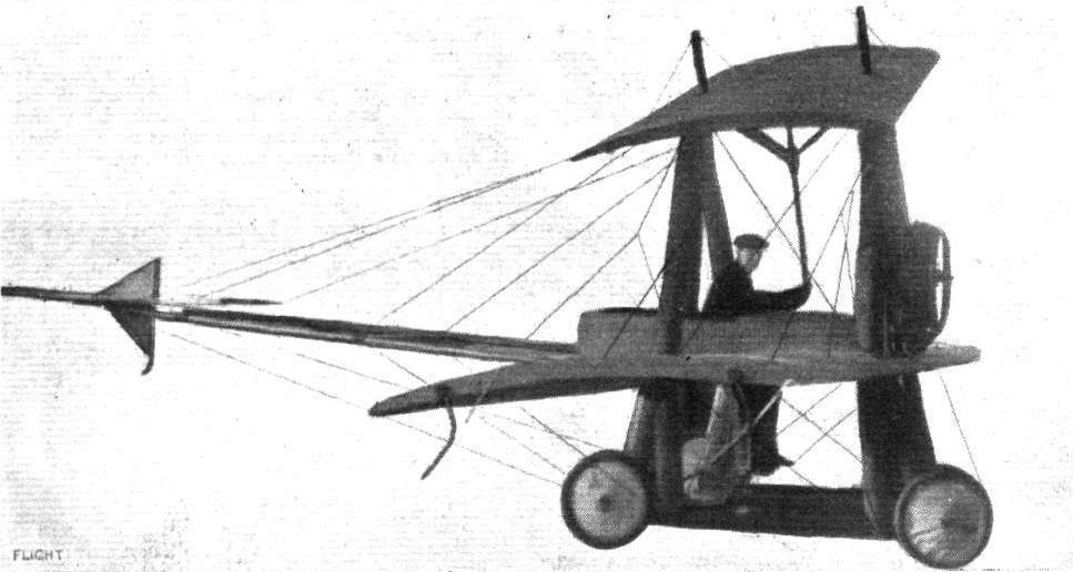
Watson No.3 biplane. The final rocking wing machine was built in 1913-1914.
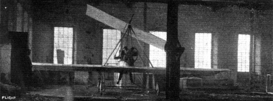
Front view of Watson No. 3.

Three-quarter front view of chassis and nacelle of the Watson No. 3, showing slots in main planes through which the pilot raises his legs when lying down inside the nacelle.
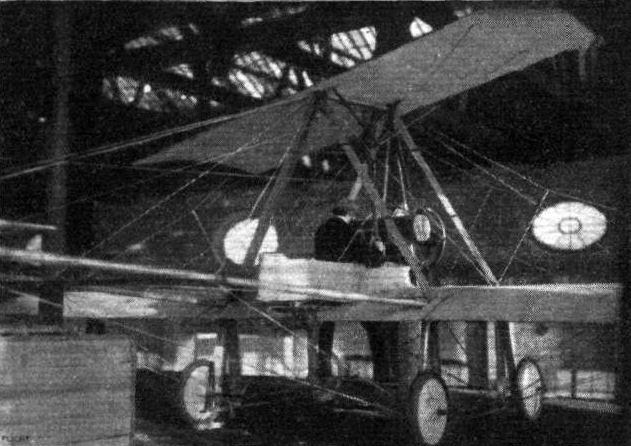
Three-quarter rear view ol Watson No. 3, now at Buc.

A FEW OF THE MACHINES COMPETING IN THE "CONCOURS DE LA SECURITE" EN AEROPLANE." - 2. The only British machine entered for the competition - the Watson rocking wing aeroplane. We are told by Mr. Summerfield, of Melton Mowbray, who piloted this machine, that the "Watson" was ruled out of the competition for no apparent reason, as it flew quite well once Mr. Summerfield got used to the rather novel control.
Flight, April 11, 1914.
THE 100 H.P. CURTISS FLYING BOAT,
WE have from time to time had occasion to describe various types of Curtiss flying boats. The subject of our scale drawings this week is the 100 horse-power English Curtiss flying boat, the rights for which, it will be remembered, are held by Messrs. White and Thompson, of Bognor. Since his return from the States, Lieut. J. Porte has, we understand, been testing this machine, and she appears to be well up to the usual high standard of sea air worthiness which has made these machines so popular in America. The boat itself is of the usual well-known Curtiss type, having a rather wide nose and tapering to a short vertical knife's edge at the stern. In the nose the bottom of the boat is perfectly flat, running gradually into a V bottom at the step, whilst the rear portion of the hull behind the step is flat. The sides of the boat slope outwards in the front portion, and there is an unusually high freeboard, which protects the occupants against water spray. From the nose of the boat a super-structure forming a wind shield runs back to a point just in front of the pilot's seat.
Constructionally the boat is built up over a framework of ash, spaced on three-inch centres, mortised at the corners, fitted with copper corner straps and each frame securely fastened with sixteen copper rivets. Longitudinal ribs or battens of one-inch square ash are run throughout the whole length of the hull. The sides of the boat are covered with a planking consisting of two layers of mahogany, whilst the bottom is triple-sheathed with first a planking of 5/16 in. mahogany, then a covering of heavy canvas set in marine glue and an outer planking of 1/4 in. mahogany. This planking runs diagonally, and extends back to the step only, the rear portion of the hull taking only a slight part of the load in rising and alighting. Eight bulkheads divide the boat into watertight compartments, so that it is practically unsinkable, for any two of the compartments are claimed to possess sufficient buoyancy to keep the entire machine afloat.
The workmanship as well as the finish of the boat is of a very high quality, and one regrets that Messrs. White and Thompson could not find the time to exhibit the machine at the recent Olympia Aero Show, where it would certainly have attracted a great deal of attention.
Two sets of seats are provided - one set for the pilot, or rather pilots, arranged side by side in front of the leading edge of the lower main plane, and another set between the leading edge and the rear spar at the lower main plane. The pilot's cockpit is unusually roomy and comfortable, and the view obtained from there is practically unobstructed in all directions. Dual control is fitted, and consists of two rotatable hand wheels, each mounted on a short forked arm which joins the vertical tubular column. This in turn is mounted on a transverse rocking-shaft projecting outside the sides of the boat, where are carried the crank levers from which cables run to the elevator. The rudder is operated by means of a pivoted footbar.
The lower plane is bolted to the gunwales of the boat from which it is stayed by means of cables. Six pairs of inter-plane struts of spruce separate the main planes, of which the upper one possesses a considerable overhang, the weight of which is taken, when the machine is at rest, partly by a steel tube running from the lower end of the outer rear strut to the end of the extension and partly by cables passing over a king post above and on the front spar of the wing.
It will be remembered that the usual Curtiss lateral control consists of two ailerons mounted on the struts in the gap between the planes. In this machine ailerons of a more orthodox type are fitted to the trailing edge of the outer portion of the upper main plane. From the accompanying scale drawings of the machine it will be seen that the two main spars are set very far apart, the front one forming the leading edge whilst the rear one is placed very close to the trailing edge of the wing.
Metal floats of the shape shown in one of the accompanying sketches prevent the wing tips of the lower main plane from cutting under. The bottom of these floats is protected against too harsh a contact with the water by means of a spring board which is secured to the nose of the float, but the rear end of which is allowed a certain amount of play in the manner shown in the sketch.
An extension of the stern post of the hull serves as a support for the partly-balanced rudder and the vertical fixed tail fin. The lower portion of the rudder is covered with wood and copper bound in order to allow of steering the machine at low speed on the water. A tail skid or skeg protects the tail planes when the machine is being beached. The fixed tail plane, which is triangular, as seen in plan, is carried on a structure of steel tubes secured to the rear portion of the hull, and to its trailing edge is hinged the divided elevator.
An outside keel in the form of a wooden strip runs along the entire length of the boat, thus protecting the bottom when running the machine up on the beach, and it is even possible, we understand, to run the machine from the hangar down to the beach by taxying along the grass on this keel.
The engine, a 100 h.p. 8-cylinder V type Curtiss, is mounted on two longitudinal ash bearers supported on a structure of welded steel tubing between the main planes. It drives directly a Curtiss propeller situated immediately behind the rear spar of the upper plane, the trailing edge of which has been cut away to provide clearance for the propeller. A very stout oblique strut runs from the engine bearers down to the bottom of the forward portion of the boat, the purpose of this strut obviously being to transmit the momentum of the engine to the boat on alighting.
The main petrol tank is situated in the boat under the rear pair of seats, whence it is forced to a small service tank between the radiator and engine by means of a small pump driven off the engine. The radiator is mounted immediately in front of the engine on extensions of the longitudinal engine bearers, a rd projecting in front of it is a starting-handle by means of which the engine can be started from the pilot's seat. It should be noted that this starting-handle does not clear the oblique strut, as it would not be possible from the pilot's seat to give the starting-handle a whole turn. For starting the engine the handle is simply put in a position slightly above the horizontal and pulled down smartly, an operation which is generally sufficient to get an explosion in one of the cylinders.
The speed of the machine with full load is about sixty miles per hour, whilst we understand it is possible to taxy it along the water at any speed up to forty miles per hour.
When taxying at this speed only a small portion of the hull just in front of the step is in contact with the water.
Flight, September 11, 1914.
THE "ROUND BRITAIN" MACHINES.
THE machine numbered 6 in the Circuit of Britain, and which was to have been piloted by Capt E. C. Bass, is
The White and Thompson Curtiss Flying Boat.
This machine, although following standard Curtiss practice in its general lay out, differs in numerous details from the American-built Curtiss boats. One of the innovations incorporated, which is apt to be overlooked by the casual observer, but which is nevertheless of the greatest importance, is the new wing section. Instead of the usual Curtiss section, one like the R.A.F. 6 has been chosen, and appears to have several advantages over the original Curtiss. The wings are rectangular, as seen in plan, and the top plane is of considerably greater span than the lower one, the weight of the extensions being taken, when the machine is at rest, by steel tubes sloping downwards and inwards to the lower extremities of the outer inter-plane struts. Interconnected balancing flaps are hinged to the rear spar of the upper plane, and not, as in the original Curtiss machines, to the plane struts.
A vertical fin is fitted above the upper main plane in order, no doubt, to counteract the comparatively large side area of the boat. Six pairs of spruce struts separate the main planes, the whole wing structure being made rigid by diagonal cross bracing.
Mounted on strong ash bearers resting on a structure of steel tubes sloping upwards from the lower main spars is the engine - a 120 h.p. Beardmore A.D. - which drives a four-bladed propeller situated behind the planes, the trailing edge of which has been cut away in the centre to provide the necessary clearance. The main petrol tank is placed inside the boat, whence petrol is pumped by means of a pressure pump to a smaller service tank mounted on the bearers in front of the engine. The capacity of the petrol tank is 60 gallons, or sufficient for a flight of about six hours' duration.
The boat, which has been constructed by Messrs. Saunders of Cowes, is a beautiful piece of work, as is to be expected from a firm of such standing. It is built up of two skins of mahogany, copper sewn, over a framework of ash and spruce. In front the boat is of roomy proportions, and affords ample accommodation for pilot and passenger, who sit side by side inside a very comfortable cockpit. From the nose to the step, which is placed a short distance behind the front spar of the wings, the boat has a Vee bottom and outward sloping sides. To the rear of the step the section may be described as being circular with a flat top. In front of the occupants the boat is covered with a curved deck, which allows any water that may wash over the top to run off easily, whilst just in front of the cockpit the deck is swept upwards to form a wind screen.
As dual controls are fitted, pilot and passenger may direct in turn, a feature which should be of great value for long flights. The controls consist of rotatable hand wheels operating the ailerons and elevator, and foot bars for the rudder. A transverse rocking shaft runs across the boat and projects on each side, where it carries the crank levers whence cables are taken to the elevator.
Mounted under the lower wing tips, to which they are attached by steel clips, are two metal floats of rectangular section and having flat bottoms, which are protected by spring boards of wood, screwed to the front of the floats and having their rear ends free to move slightly up and down.
The tail planes are of the usual Curtiss type, and consist, as will be seen from the accompanying illustrations, of a large vertical fin screwed to the top of the rear portion of the boat and braced by steel tubes, a partly balanced rudder, a fixed stabilizing plane mounted on top of the fin, and a divided elevator. The lower portion of the rudder is covered with metal and serves as a water rudder when taxying.
The weight of the machine empty is 1,600 lbs., and with full load, including pilot, passenger, and six hours' fuel, the weight is 2,400 lbs., giving a loading of 6 lbs. per sq. ft. The actual speed is not known, but judging from previous Curtiss boats and making allowance for the higher horse-power and new wing section, it is probably about 70 m.p.h.
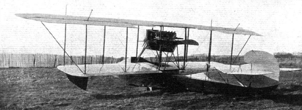
THE 100 H.P. CURTISS FLYING BOAT. - Three-quarter view from behind.

W&T Curtiss type flying boat. An improved version of the Curtiss F was flown at Middleton in March 1913.
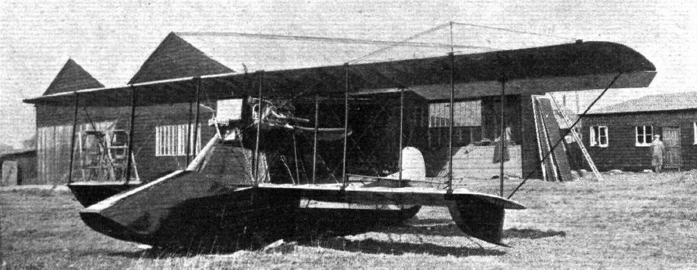
THE 100 H.P. CURTISS FLYING BOAT. - The Curtiss Model F was the epitome of elegant flying-boat design in the pre-war years. This one was built under licence in England at the White & Thompson works at Middleton, Sussex, in 1913. The classic Curtiss inter-wing ailerons have been replaced by conventional ailerons on the upper wing trailing edge.
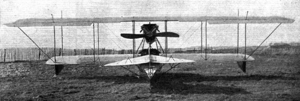
THE 100 H.P. CURTISS FLYING BOAT. - View from behind.
ROUND BRITAIN MACHINES, No. 6. - Three-quarter rear view of the White and Thompson flying boat.

ROUND BRITAIN MACHINES, No. 6. - Front view of the White and Thompson (Curtiss Pat.) flying boat.
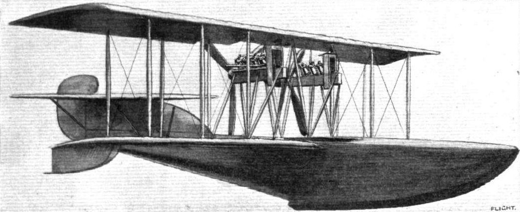
ROUND BRITAIN MACHINES, No. 9. - The White and Thompson (Curtiss) flying boat.

The nose of the Curtiss flying boat, and on the right the tail skid.
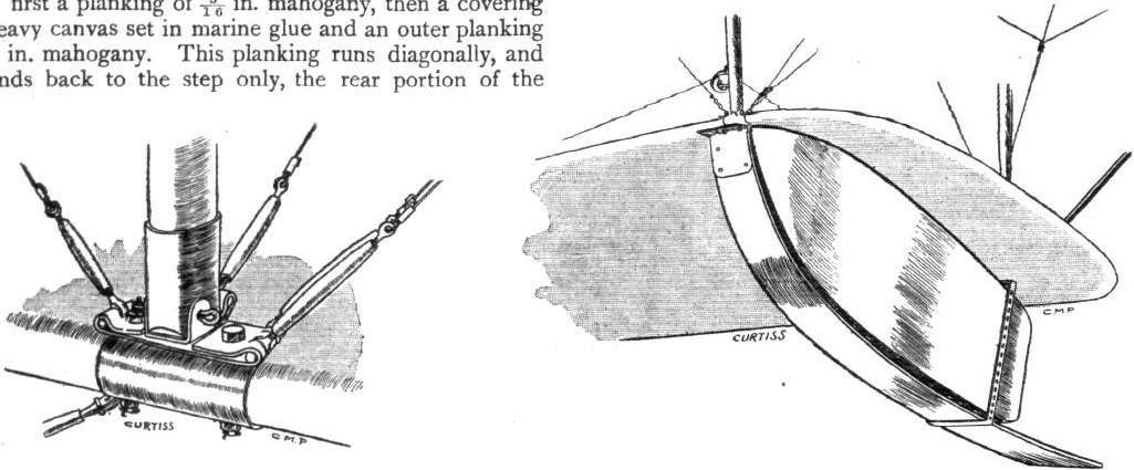
One of the inter-plane strut sockets of the Curtiss flying boat, and on the right one of the wing tip floats.
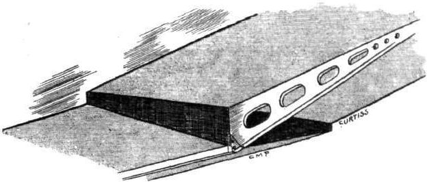
View from underneath of the step in the Curtiss flying boat.
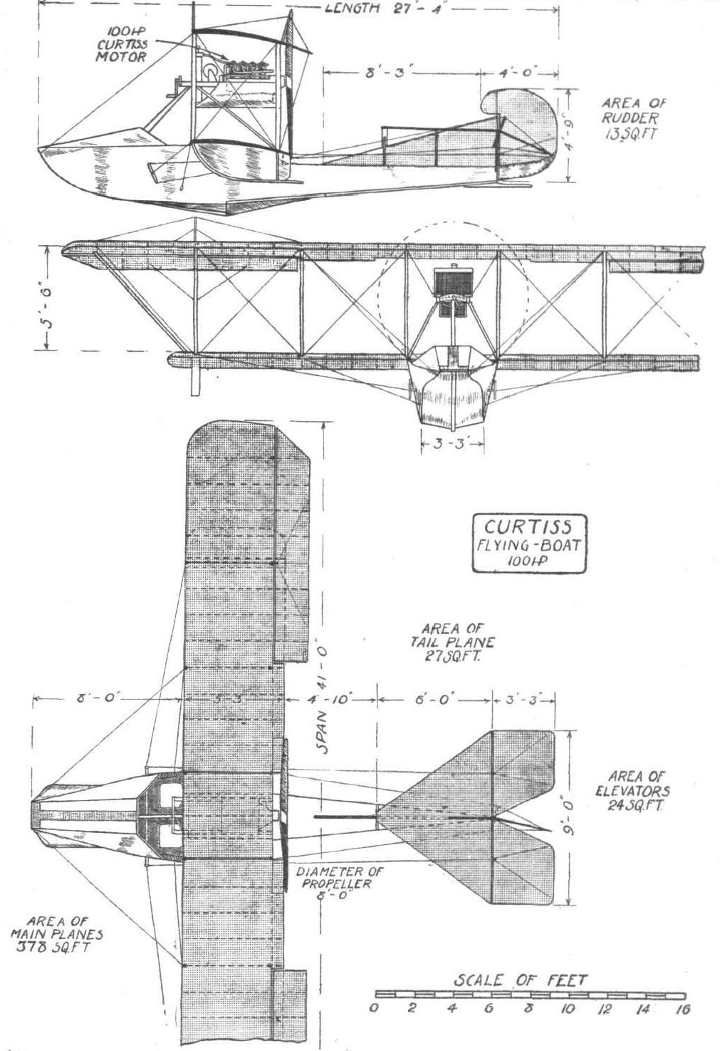
THE 100 HP. CURTISS FLYING BOAT. - Plan, side and front elevation to scale.

ROUND BRITAIN MACHINES, No. 6. - The White and Thompson (Curtiss) flying boat. Plan, front and side elevations to scale.
Flight, October 9, 1914.
THE "ROUND BRITAIN" MACHINES.
THE seaplane for which Mr. Loftus Bryan had been nominated pilot in the circuit of Britain, and which had been officially numbered 9, was
The White and Thompson Flying Boat.
As regards the general disposition of its component parts this machine adheres fairly closely to the practice followed in the original American Curtiss flying boats, but the greater portion of the detail work has undergone alteration and modification with the object of improving, both aerodynamically and constructionally, upon its American prototype.
Aerodynamically the greatest improvement has possibly been effected in the shape of the wing section, which is a reproduction of the famous R.A.F. 6, that has proved so efficient both under laboratory tests and on full - sized machines. In plan the wings are of rectangular form and the upper plane has a very pronounced overhang braced by steel tubes running to the bases of the outer interplane struts. The balancing flaps are hinged to the outer portion of the upper rear spar and not, as in the original Curtiss, to the plane struts. Consistent with modern practice, the flaps are inter-connected, so that when one is depressed the other is correspondingly elevated. The spars of the lower main plane pass through the boat, to which they are further stayed by four steel tubes running from the plane struts immediately outside the engines to the sides of the boat.
Instead of running vertically from top to bottom plane the inner pair of interplane struts form an inverted V as seen from in front, so that their upper apices meet on the centre line of the upper plane. Between the planes and spaced about 8 ft. apart are mounted two Curtiss engines of the OX model, each of 90 h.p. and driving a three - bladed propeller with adjustable pitch. The method of mounting these engines is the same as that employed when only a single motor is fitted, and consists, as our readers will remember from previous descriptions of Curtiss machines, of stout engine bearers of ash supported on a structure of steel tubes resting with their lower extremities on the spars of the lower main plane. In front of the engines are mounted the two radiators, which in this machine are placed astride the engine bearers. The engines are braced forward by means of two struts running to the keel of the boat some distance behind the bow. As the engines are not enclosed in any way, they are easily accessible should it become necessary to effect minor adjustments.
The boat or hull, which has been built by Messrs. Williams and Co. of Littlehampton, is of approximately rectangular section in front, whilst gradually running into a circular section at the rear. Being about 4 ft. deep and of practically the same beam, it affords ample accommodation for pilot and passenger, who sit side by side just in front of the leading edge of the main planes. Curtiss control of the usual dual type is fitted, so that either of the occupants can pilot the machine. Behind the seats and inside the boat is placed the petrol tank, which has a capacity of 90 gallons, or sufficient for a flight of 6 hours' duration.
The tail planes are of the usual Curtiss form, but are slightly larger in size than those fitted on the single-engined machines. A vertical fin resting on the top of the rear circular portion of the boat, to which it is braced by means of steel tubes, provides the fixed vertical surface aft. To the trailing edge of this fin is hinged a large rudder, which has a small forward extension above the fixed stabilising plane. The lower part of the rudder is covered with metal for the sake of protection. The large horizontal tail plane is mounted on top of the vertical fin and braced by tubes to the boat. A divided elevator hinged to the rear edge of the tail plane completes the tail unit.
The weight of the machine empty is 2,000 lbs., and with full load, including pilot, passenger and 6 hours' fuel, 3,000 lbs.
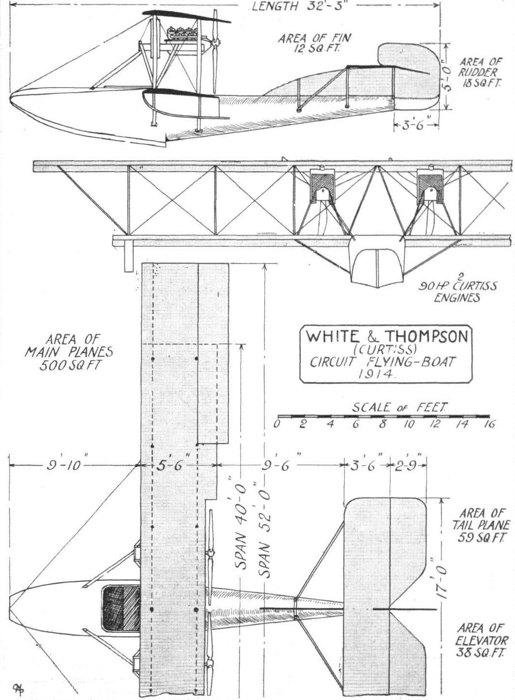
ROUND BRITAIN MACHINES, No. 9. - The White and Thompson flying boat. Plan, side and front elevations to scale.
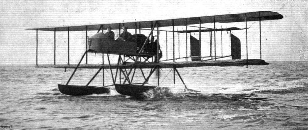
The "Wight" hydro-aeroplane, built by Messrs. J. S. White and Co., of Cowes. - A slightly modified design will be seen at Olympia, the principal alterations being the fitting of a 200 h.p. Canton-Unne engine and the provision of two additional struts between the ffoats and the upper planes at the rear of the machine.
Flight, March 14, 1914.
WHAT THERE WILL BE TO SEE AT OLYMPIA.
THE EXHIBITS.
Wight (Samuel White and Co.). (39.)
THE Wight seaplane exhibited by Messrs. Samuel White and Co. will be somewhat similar to the machine shown in incomplete form at last year's Aero Show, although, of course, several alterations suggested by a great amount of flying during the past season have been effected. Most interesting, from an aerodynamical point of view, is the peculiar double-cambered wing section which several people were rather inclined to scoff at last year but which has since proved its worth. In fact so pleased is its designer, Mr. Howard T. Wright, with it that he has applied it to the propeller also, and with equally good results. We understand that this propeller has been tried against several well-known makes and has proved superior to them, at least for this particular machine.
The engine fitted on this year's machine is a 200 h.p. Salmson mounted at the rear.
Flight, March 28, 1914.
THE OLYMPIA EXHIBITION.
THE EXHIBITS.
WIGHT SEAPLANE (J. SAMUEL WHITE AND CO., LTD.).
THE 200 h.p. seaplane shown on this stand is an enlarged edition of the 160 h.p. machine which has been doing a good deal of flying lately on the south coast piloted by Mr. Gordon England. It is a development of the machine shown in incomplete form at Olympia last year.
The main characteristics of this machine are the unusually long floats and the peculiar double cambered wings invented by its designer, Mr. Howard T. Wright. This particular wing section has proved very efficient in every way. The lift to drift ratio is very good, and the travel of pressure is comparatively small, so that the machine possesses a considerable amount of inherent stability.
The engine fitted is a 200 h.p. water-cooled Salmson (Canton-Unne) mounted on double bearings in the rear of the nacelle and driving a Howard Wright propeller, the blades of which have a similar section to that of the wings. The nacelle is built of spruce throughout, and the various members are connected by ingenious steel clips, some of which are shown in the accompanying sketches. The pilot's and passenger's seats are arranged tandem fashion, and control is by means of a single central lever and a foot-bar. A complete set of instruments is carried, consisting of oil and petrol gauges, air speed indicator, aneroid, clock, revolution indicator, compass and tell-tale glasses. Provision has been made for a wireless set, but this is not fitted at present. To the right of the pilot's seat is mounted a compressed air starter, working at a pressure of 150 atmospheres.
The two main floats, as pointed out previously, are unusually long and are provided with three steps. The nose of the floats is of the displacement type, running gradually into a slightly curved planning surface, at the steps, becoming flatter towards the stern, where the last step is almost perfectly flat. The floats are built up of three-ply wood on a strong framework of elm. They are divided into six watertight compartments, and are further strengthened by a longitudinal partition running throughout the whole length.
The tail planes consist of a fixed stabilising plane, to the trailing edge of which is hinged the elevator. Underneath the stabilizing plane are mounted the twin rudders, which are partly balanced. No tail float is fitted, the main floats being sufficiently long to protect the tail planes against contact with the water when the machine is at rest. The workmanship throughout is extremely good, and one is not surprised, in view of the excellent performances of the 160 h. p. machine, to learn that several of these seaplanes have been ordered by the Admiralty.
Flight, May 29, 1914.
THE "WIGHT" SEAPLANE.
AMONG the ever-increasing number of British seaplanes, few have met with greater success than have Wight seaplanes designed by Mr. Howard T. Wright and built by Messrs. J. Samuel White and Co., Ltd., of Cowes. The excellent performances of these machines are somewhat apt to escape the notice that they certainly merit, since they are at present built for the British and foreign navies only and their flights in public have been limited to trial nights and delivery tests. There is no lack of recognition by our own and foreign governments, however, and several of these machines have already been delivered, whilst sufficient orders have been received to keep the firm very busy indeed for a long time to come.
One of these machines was, it will be remembered, exhibited at the last Olympia Aero Show when it caused considerable interest owing to its many original features. Most notable among these are the unusually long floats, and the peculiar double camber on the upper surface of the wings. It is undoubtedly chiefly due to this double camber that the machine possesses such a good speed range - from 78.9 miles per hour to about 35 m.p.h. with full load of fuel, wireless apparatus, pilot and passenger. The most marvellous point, however, does not so much lie in the speed range itself, although that is uncommonly good, but more in the attitude of the machine throughout the entire range of speeds. The main planes and the tail plane are so designed that as the speed of the machine increases, the lift of the tail plane increases at a different ratio from that of the main planes, in such a manner that, as the speed goes up, the angle of incidence of the main planes in relation to the horizontal decreases without necessitating use of the elevator. When the maximum speed has been reached, the main planes are flying at a negative angle of incidence of 1°, whilst the tail plane has a negative angle of incidence of 4°. Any attempt to increase the speed beyond this point causes a top pressure on the tail plane and the machine begins to climb. It will therefore be seen that it is possible to fly the machine simply by closing or opening the throttle without using the elevator, as longitudinal stability is perfect under all speeds.
The lateral stability is more difficult to explain, but is none the less pronounced. We had occasion recently to observe the machine in flight, and she appears to bank up to the right degree in making a turn without any use of the ailerons, and when flying in a straight line, even on a windy day, the ailerons are rarely called into play.
Excellent as is the behaviour of the machine in the air, her performances when on the sea are almost even more so. The long three-stepped floats leave the water in a perfectly clean manner, without the huge spray of water usually set up while a machine is gathering speed. The nose of the floats leaves the water first, then the first step, and so on, until gradually the whole of the floats leave the water without any jerk whatever. When starting for a flight in a rough sea, the long narrow floats plough their way through the waves without causing the machine to rise and sink with the swell. Alighting on the water is effected by throttling down the engine until a sufficiently low flying speed has been obtained to allow of settling down on the surface of the sea gently and without shock. One of the accompanying photographs shows in a most striking manner the clean wake of the floats under these conditions. When taxying on the surface of the sea the machine answers her rudder beautifully, and it is possible to make a complete circle of only about 30 ft. diameter. With a full load including fuel, wireless apparatus, pilot and passenger, the machine reaches an altitude of 3,000 ft. in 7 1/2 mins., and recently experiments were made with an additional load of 400 lbs., with which the machine reached 3,000 ft. in 13 1/4 mins. By sacrificing the low starting and alighting speed, a much greater load could be carried, but Mr. Howard Wright is - rightly we think - in favour of a machine possessing a wide speed range.

The "Wight" seaplane in flight.
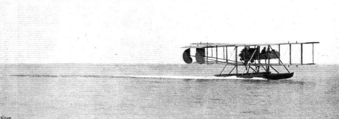
The "Wight" seaplane alighting. This photograph gives a good idea of the small wake set up by the long narrow floats.
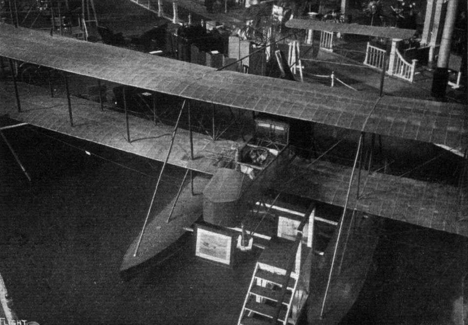
VIEW FROM ABOVE OF THE WIGHT SEAPLANE. - This photograph clearly shows the peculiar double cambered upper surface of the wings.
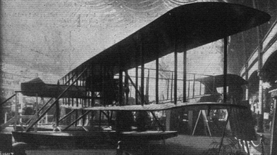
The Wight seaplane.
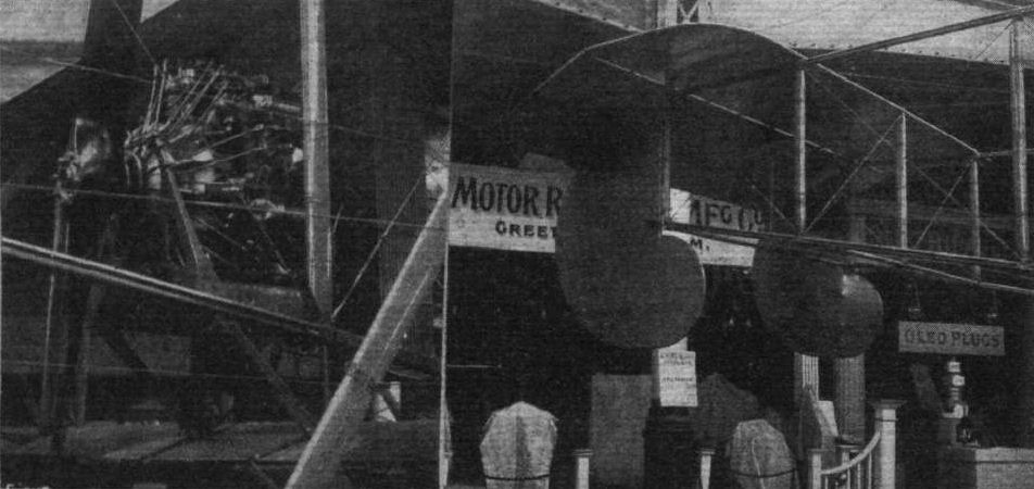
THE 200 H.P, SALMSON ENGINE ON THE WIGHT SEAPLANE. - On right, tail planes of the Wight seaplane.
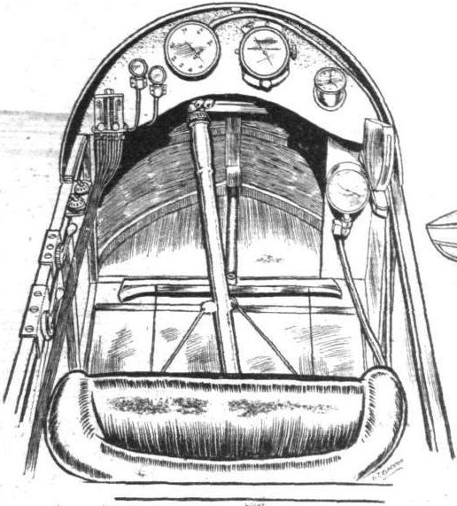
Pilot's cockpit.
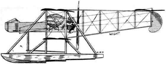
The 200 h.p. Wight seaplane.

One of the main floats.
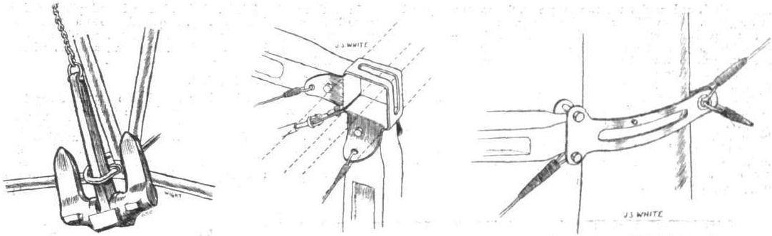
Left: The very substantial anchor of Wight seaplane. Right: Attachment of upper nacelle longerons to plane strut. Centre: Method of attaching struts to longerons in nacelle of Wight seaplane.
Flight, June 5, 1914.
THE PRINCE HENRY CIRCUIT, 1914.
MACHINES IN PRINCE HENRY CIRCUIT.
The A.E.G. Biplane is of the ordinary tractor type, having straight wings (as seen in plan, but set at a pronounced dihedral angle). The main planes are so designed that for purposes or transport they can be folded flat along the sides of the fuselage. The chassis has three wheels, of which the front one, the object of which is to protect the propeller, is sprung by means of coiled springs on a steel tube sloping backwards to the nose of the fuselage.
Flight, August 21, 1914.
AIRCRAFT "MADE IN GERMANY"
WHICH MAY BE EMPLOYED AGAINST THE ALLIES.
5. The A.E.G. Biplane
is characterised by back-swept wing tips, its main planes being straight, as seen in plan. The upper one, which has a considerable overhang, is also straight, as seen from in front, but the lower is set at a pronounced dihedral angle. The fuselage of this machine is unusual in that it is of rectangular section in the front portion, whilst being of triangular section at the rear. A flexing elevator somewhat similar to that employed on the Taube type monoplane is fitted. The rudder is situated wholely above the tail plane and is balanced. The chassis is of the three-wheeled type, having two main wheels which ordinarily take the weight of the machine, and a third mounted on a buffer, which prevents the machine from standing on its nose in case of a bad landing. A 100 h.p. N.A.G. engine is fitted.
The seats are arranged in tandem, the pilot sitting well to the rear, whilst the passenger is situated approximately over the centre of gravity of the machine, so that his presence or absence does not affect the longitudinal stability.

A.E.G. Z 3 [95 hp NAG motor, wings could be folded / German Patent 274.115]
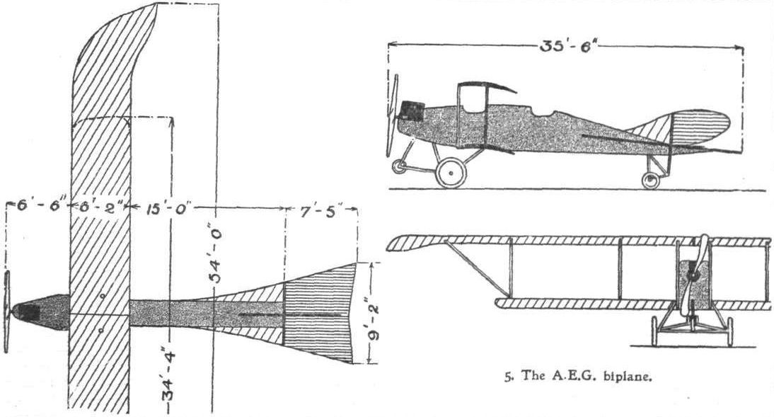
5. The A.E.G. biplane.
Flight, August 21, 1914.
AIRCRAFT "MADE IN GERMANY"
WHICH MAY BE EMPLOYED AGAINST THE ALLIES.
6. The New A.E.G. Biplane
differs from the machine described above in that it has no back-swept wing tips. The main planes are straight, as seen in plan, but are set at a very pronounced dihedral angle. For purposes of transport they can be folded flat along the sides of the fuselage. The chassis has three wheels, of which the front one, protecting the propeller, is sprung by means of a coil spring on a steel tube sloping backwards to the nose of the fuselage.

6. The new type A.E.G. biplane.
Flight, September 25, 1914.
AIRCRAFT "MADE IN GERMANY"
WHICH MAY BE EMPLOYED AGAINST THE ALLIES.
1. The A.E.G. Seaplane
is a newcomer into the German waterplane industry. The machine illustrated hereby was designed for the Warnemunde-Scandinavia Race, and is chiefly interesting on account of the wing mounting, which is such that the main planes can be folded back along the body for purposes of transport. The rectangular section body tapers towards the nose, where is mounted the 150 h p. Benz engine. Aluminium sheeting with inspection doors covers the front portion, whilst the rear part is covered with fabric. The two seats are arranged in tandem, the pilot occupying the rear one. By undoing the drag wires running to the fuselage the main planes can be folded along the sides of the body, the lower ones passing underneath it. The whole operation of folding the wings can be accomplished in under two minutes. The two main floats, which are of the single step type, are built up of two skins of mahogany over a framework of ash, and are fitted with bulkheads dividing them into watertight compartments. As the floats are of ample size - their displacement is three times the weight of the machine - they float very high on the water when the machine is at rest. The floats are carried on a framework of streamline steel tubes, to which they are attached, each by four rubber shock-absorbers. In addition to the usual equipment, a complete set of instruments for wireless telegraphy is carried.
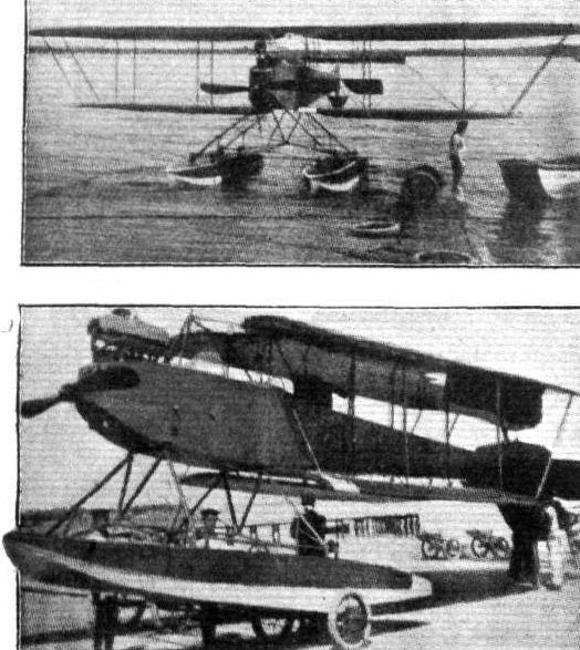
1. The A.E.G. Tractor seaplane.
Flight, September 25, 1914.
AIRCRAFT "MADE IN GERMANY"
WHICH MAY BE EMPLOYED AGAINST THE ALLIES.
2. The Ago Seaplane
is of the engine-behind or "pusher" type. It is characterized by a peculiarly-shaped nacelle, which is very deep in front and runs to a horizontal knife edge at the rear. The engine - a 150 h.p. Argus - is mounted in the rear of the nacelle, and a short distance above the upper longitudinals. The centre portion of the trailing edge of upper and lower planes has been cut away in order to provide a clearance for the propeller. In front of the engine are the two seats arranged tandem fashion, the pilot occupying the front seat. To the trailing edge of the upper main plane, which has a considerable overhang, are fitted ailerons of large area. These have a greater chord at their outer ends than at the root, in order to render them more efficient.
Carried on an outrigger consisting of four tail booms connected with struts and cross-members, and diagonally cross braced, are the tail planes, which consist of a slightly cambered fixed tail plane, to the trailing edge of which is hinged an undivided elevator, and of three vertical rudders. Two cylindrical tail floats take the weight of the tail planes when the machine is at rest.
The two main floats, which are of the plain non-stepped type, are carried on a framework of steel tubes coming down from the lower main plane. In addition to the floats, four wheels are fitted for use over land. These wheels can be raised clear of the water by means of a lever in the pilot's cockpit when it is desired to start the machine from the sea.

2. The Ago seaplane.

2. The Ago seaplane.
Flight, August 21, 1914.
AIRCRAFT "MADE IN GERMANY"
WHICH MAY BE EMPLOYED AGAINST THE ALLIES.
1. The Ago-Arrow Biplane
is, as the name implies, of the type deriving its name from the peculiar backward slope of its main planes. When viewed from in front the upper plane is straight, whilst the lower one possesses in addition to its backward slope, a comparatively great dihedral angle. The fuselage, which is of rectangular section, tapers toward both ends, the streamline form being further improved by a turtle back in which openings have been cut out for the engine and occupants. The seats are placed very far apart, the pilot's being placed nearly halfway along the fuselage, whilst that of the passenger is situated immediately behind the engine. Either a 100 h.p. Mercedes or a 150 h.p. Argus motor may be fitted. With the former the speed of the machine is about 60 and with the latter 68 m.p.h. The chassis is of a type which has attained great popularity in Germany and consists of two pairs of steel tube struts, each pair of which forms a V as seen from the side. A single tubular axle sprung by rubber shock absorbers and carrying the two disc wheels rests in the angle between the front and rear struts. No skids are incorporated in the chassis, but a small tail skid takes the weight of the tail planes when the machine is at rest.

1. The Ago Arrow biplane.
Flight, August 21, 1914.
AIRCRAFT "MADE IN GERMANY"
WHICH MAY BE EMPLOYED AGAINST THE ALLIES.
2. The Ago Racing Monoplane
is in some respects reminiscent of the Morane. It is - which is unusual for a German machine - a single-seater but otherwise incorporates many of the features of the biplane. The rectangular section fuselage tapers to a horizontal knife edge at the rear and runs to a point in the nose of the machine where is accommodated the engine - a 150 h.p. Argus. As frequently seen on modern German aeroplanes, the radiator is mounted above the engine. The chassis is of a very simple form and consists essentially of two pairs of tubes bent in the form of a U from which is slung the tubular axle. Wing warping is employed for lateral control, the warp cables being taken to a lower pylon of steel tubes whilst the upper bracing cables are secured to the top of a similar pylon resting on the upper longerons of the fuselage.

2. The Ago Racing monoplane.
Flight, September 25, 1914.
AIRCRAFT "MADE IN GERMANY"
WHICH MAY BE EMPLOYED AGAINST THE ALLIES.
3. The Ago Tractor Seaplane
is a fuselage biplane, with accommodation for pilot and passenger sitting one in front of the other. Of the main planes, which are set at a dihedral angle, ailerons are fitted to the upper one only. The two floats are of the single stepped type, and are carried on a series of A steel tubes attached to the lower plane at its junction to the inner pairs of interplane struts.
Flight, September 25, 1914.
AIRCRAFT "MADE IN GERMANY"
WHICH MAY BE EMPLOYED AGAINST THE ALLIES.
2a. The New Ago Seaplane
is a later type than machine No. 2, having been designed for the Wamemunde-Scandinavia Race. In some respects it is reminiscent of the Wight seaplane, especially as regards the long floats and the nacelle. The former are of the displacement type in front, running out to a flat bottom at the rear. Air is admitted to the step by means of metal tubes passing through the interior of the float and sloping slightly backwards. Connection between floats and nacelle is by means of stout ash struts, as this firm is of opinion that good ash is more suitable than steel for seaplane work.
The nacelle projects a considerable distance out in front of the main planes and is fitted in front with a wind-screen. The two seats are arranged one behind the other, the pilot sitting in front. The tail planes are carried on an outrigger, and consist of a fixed stabilising plane, elevator, vertical fins and rudder. The vertical area of fins and rudders does not appear to be sufficient to counteract the large side area of the nacelle and the two long floats, although the rear portion of the nacelle and the engine are to the rear of the c.g. With a 150 h.p. Argus engine the speed of this machine is 56 m.p.h.
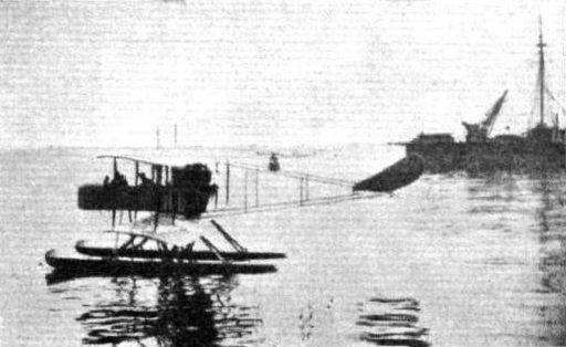
2A. The New Ago seaplane.
Flight, October 9, 1914.
AIRCRAFT "MADE IN GERMANY"
WHICH MAY BE EMPLOYED AGAINST THE ALLIES.
5. The Albatros Propeller Seaplane
is of an older type, and the firm is, we believe, discontinuing building this type. The main planes, which are of rectangular plan form, are of large span, and both upper and lower planes are fitted with ailerons. Pilot and passenger are accommodated side by side inside a shallow nacelle, and dual control is fitted, or, more correctly speaking, the single control wheel can be shifted from side to side so that either of the occupants may pilot the machine. A front elevator of the Farman type is fitted, and at the rear, carried on an outrigger of the usual form, is a biplane tail. Between the upper and lower tail planes are mounted three vertical rudders side by side, and to the trailing edge of the upper tail plane is hinged the rear elevator. The engine - a 100 h.p. Argus or Mercedes - is mounted at the rear of the nacelle, and in front of it, supported on the engine bearers, is the radiator.
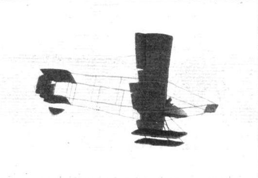
5. The Albatros seaplane.
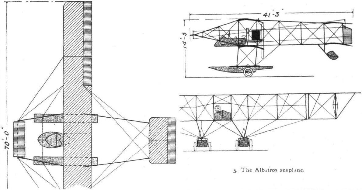
5. The Albatros seaplane.
Flight, April 4, 1914.
THE 100 H.P. ALBATROS BIPLANE.
EVIDENTLY the German constructors have confidence in the ability of their products to compete against machines of British manufacture, for again a German machine - this time a 100 h.p. Albatros biplane - has arrived in this country with a view to being submitted to tests at Farnborough. As regards workmanship and soundness of construction, this latest arrival to these shores must be admitted to be equal to the best of British machines, and judging by the amount of flying done on these machines in Germany and the popularity that they have attained in that country, there is every reason to believe that they are as efficient aerodynamically as they are robust constructionally. The machine, of which we publish scale drawings and illustrations this week, arrived at Hendon on the morning of Friday last on its lorry, and was in the air the same afternoon.
After giving the engine - a 100 h.p. Mercedes - a preliminary run, the pilot, Herr Robert Thelen, had the machine wheeled up on the pier in front of the Grahame-White offices, and, when warned against the soft ground at the end of the pier, he laughingly replied that he would be off by the time he got to the soft ground. As the wheels reached the end of the pier the nose of the machine shot upwards, the tail skid touched the ground and the great biplane climbed upwards at an angle reminiscent of the little Sopwith flown by Mr. Hawker.
Like the majority of German machines, the Albatros biplane is of the tractor type, but the wings are straight, as seen in plan view, instead of being swept backwards as in several other machines hailing from that country. Among the many interesting features the construction of the fuselage is worthy of notice, for it is built up without the use of the ordinary diagonal cross bracing, the necessary rigidity being obtained by the covering, which is of three-ply-wood.
According to calculations carried out by the Albatroswerke and corrected by Deutsche Versuchsanstalt fur luftfahrt, the factor of safety of the fuselage of the Albatros biplane is about 60, and the bending resistance of this type of fuselage is 2.5 times greater than that of a diagonally wired fuselage of the same outside dimensions and having members of the size usually employed in structures of this type. The Versuchsanstalt also states that the Albatroswerke are justified in concluding that the bending resistance of the veneer type of fuselage is greater than that of a cross wired fuselage of the same weight.
There are six longerons of ash, one in each corner of the rectangular section fuselage and one about half-way up each side. The struts are also of ash, and occur at frequent intervals along the whole length of the fuselage. The three-ply covering is tacked to struts and longerons. From the nose up to a point in front of the tail fin the deck of the fuselage is given a streamline form by means of a curved turtleback, whilst the under surface is flat.
The 100 h.p. Mercedes engine is mounted on strong ash bearers in the nose of the fuselage, and the radiator as will be seen from the accompanying illustrations is supported on brackets immediately above the engine. The pilot's and passenger's seats are arranged tandem fashion inside the roomiest portion of the fuselage, the pilot occupying the rear seat. Between the passenger's seat and the engine are the petrol and oil tanks, which have a capacity sufficient for a flight of 4 1/2 hours' duration. The seats are unusually comfortable, being well upholstered. A neat instrument board, carrying a variety of instruments, is situated in front of the pilot's seat, as shown in one of the sketches, whilst in front of the passenger or observer is a small folding table.
The chassis is of a very simple type, and consists of two pairs of V tubes of steel carrying the large diameter tubular axle, which is sprung from the chassis by means of rubber cord. Leather guards protect these cords against contact with the ground in a heavy landing and prevent them from being splashed with mud. Pivoted around the wheel axle, and operated by means of a cable from the pilot's seat, is a very effective brake, which pulls the machine up very quickly on landing; it may also be used to prevent the machine from going forward while the pilot is testing his engine before a flight. By means of this brake and the hand-operated starter, the pilot is able to start the machine without any outside assistance, a very desirable feature in a machine for military purposes.
The main planes, as will be seen from the accompanying scale drawings, have the two main spars comparatively close together, the rear spar occurring about half way along the chord. The rear portion of the wing therefore possesses a considerable amount of flexibility, further increased by having the extreme rear part of the wing single surfaced for a distance of about a foot from the trailing edge. This, it will be seen, provides a form of progressive springing of the trailing edge, to which the machine no doubt owes a considerable amount of its lateral stability. Ailerons are fitted to both upper and lower planes, and the crank levers for operating these are not set at right angles to the planes, as it is usually done, but lie parallel to the planes and work in slots cut in the upper plane. From the end of these crank-levers cables pass round pulleys in the lower plane, and thence to the control wheel. The ailerons on the lower plane are set at a slightly negative angle of incidence, thus probably further enhancing the lateral stability.
Streamline steel tube struts connect the planes, and the attachment of these struts to the spars is highly original. A steel shell of the shape shown in the accompanying sketch rests on a paper fibre pad shaped to fit the curvature of the plane. Inside the shell is carried a steel ring, to which are anchored the cross-bracing cables, or, more correctly speaking, the turnbuckles for the cables. A bolt passes through the shell and the spar, and is locked on the other side of the plane by means of a nut.
The wings are attached to the fuselage by vertical bolts, as shown in the sketch, whilst the upper planes are secured at the centre to a cabane consisting of four streamline steel tubes bolted to the upper longerons of the fuselage, and carrying at their upper extremities a horizontal tube which is provided with flanges for the attachment bolts. By undoing half a dozen bolts, the planes can be detached from the fuselage, and folded flat against one another without removing the inter-plane struts. We understand that three sets of main planes of different size can be used for the same fuselage according to whether the machine is wanted to be speedy, for scouting work, or slower but with a greater weight-carrying capacity. Some of these machines, we learn, can even be converted into monoplanes by fitting a single pair of wings in the usual place. The cabane mentioned above then serves as a support for the upper bracing cables. Also the machine may be turned into a seaplane by substituting floats for the wheels.
The tail planes are of the usual type, consisting of a fixed stabilizing plane, to the trailing edge of which is hinged the divided elevator. A triangular vertical fin is mounted on top of the fuselage and secured to the stern-post, which also carries the rudder. A strong tail skid, sprung by rubber bands, protects the tail planes against contact with the ground.
With the medium-sized wings fitted at present, the machine has a speed of about 70 m.p.h. and weighs about 1,500 lbs. empty. The workmanship and finish are excellent, and the behavior of the machine in the air, as far as it was possible to judge from a flight with Herr Thelen, appears to be very good. When struck by gusts or running into remous the machine rose and sank on an even keel, the ailerons rarely being called into play. The climbing capabilities are extremely good for a machine of this size, and the speed range, without knowing the actual figures, seems to be considerable. With the engine throttled right down the machine glided very flat, but even when flying absolutely cabre we did not notice any tendency whatever to side-slip, nor did the pilot appear to experience any difficulty in getting her nose down again. On steeply banked turns, the bank being increased by using the ailerons, the considerable side area of the fuselage appeared to prevent side-slipping.
We understand that if the machine passes her tests, and there are reasonable prospects of repeat orders, it is the intention of the Albatros firm to establish a factory in this country.
Flight, April 11, 1914.
ROBERT THELEN.
NOT only is Robert Thelen one of the most prominent of German pilots, but he is also one of the pioneers, for his certificate is numbered 9, and he was the third to learn on a Wright biplane in Germany. For a considerable time past he has been flying the Albatros biplane, and it is in order to demonstrate this type of machine to the British Government officials that he is at present in England. It will be recalled that he holds the world's height record for pilot and three passengers with 3,750 metres.
THE HAWK.
Flight, April 18, 1914.
SOME IMPRESSIONS OF A CROSS-COUNTRY FLIGHT.
"I AM taking the Albatros biplane to Farnboro this afternoon. Would you care to accompany me ?" This was the invitation I received the other day from Herr Thelen, the famous pilot of the Albatros biplane. Needless to say I accepted the invitation, and a few minutes afterwards we were on our way to the Hendon Aerodrome. Arrived there the mechanics were busy filling up tanks and going over everything to see that the machine was in order, while Herr Thelen and I sat down to study the map. I had, of course, been to Farnborough several times, but never by air, whilst Herr Thelen was perfectly unacquainted not only with the route but also with the place itself.
However, after consulting Mr. E. R. Whitehouse and obtaining some valuable information from him as to the best route to follow, we decided that, as it was a comparatively clear day, we ought to be able to find our way, and so we climbed on board and, after a preliminary run of the engine, Herr Thelen gave the order to let go and we were off. A couple of circuits of the Aerodrome gave us sufficient altitude to set out across country, and soon we were heading past the Welsh Harp, which glittered bright below.
According to the directions given us by Mr. Whitehouse we should leave Harrow on our right. I looked for it in vain for some moments, first through the windscreen and later, as Harrow-on-the-Hill refused to reveal itself through the mica screen, I craned my neck in order to look over it; my efforts were rewarded, for there, on the right, I could discern the church. From this height, however, it was a little difficult to understand how Harrow has derived its appellation, for of the Hill, on which I knew the church to be built, I could see no signs; it looked, in fact, as fiat as all the surrounding country. This is one of the difficulties of cross-country flying, you may be coming down in a field which looks flat from above, but which, on closer examination, turns out to be the side of a hill.
The weather had been beautifully calm when we left Hendon, the pen on the wind gauge dragging itself lazily along the O line, but clouds were gathering and it looked for some time as though the element in which we were flying was going to be semi-aquatic. Shortly after passing Harrow we ran into a remous which caused us to drop a considerable distance. The sensation, when the "solid" air was met again, was exactly similar to that experienced on a ship in a rough sea.
In a few minutes we could see the reservoir at Staines approaching rapidly, and as this was one of the landmarks we had to pass, I began to feel that it would probably be easier to find our way than I had anticipated, in spite of the mist which hung over the Thames Valley and prevented us from seeing more than a couple of miles in any direction. Near the Staines reservoir a balloon flying very low passed immediately underneath us, and was soon out of sight again.
After indicating to Herr Thelen, by means of a sort of deaf and dumb system decided on before the start, to lay the course a little more to the South, I fell to experimenting with locating various places on my map. The numerous bends in the river around Staines afforded excellent opportunities for doing so, and I was thinking that I was doing rather well, when it suddenly dawned upon me that I was holding my map the right way up - that is to say with the North arrow pointing away from me - whilst we were flying in a South-Westerly direction and that, therefore, the bends in the river, which I saw on the right, were to the left of our course as I was looking at it on the map. By the time I had got the map turned round we had left the river behind, and I was suddenly disturbed in my geographical studies by a yell from the pilot. Looking back I saw him pointing to the South, where, after a few moments, I picked out the race track at Brooklands.
I now began to look out for the sheds at Farnborough, which I had been told one could see - in clear weather of course - shortly after passing the reservoir at Staines. I soon picked out the London and South-Western Railway, which was, however, far less conspicuous than were the roads, which, as they were dry, were plainly visible from above. In front and on the right I saw a white sheet which at first I took to be Virginia Water and, thinking that we had turned too far North I was just going to give directions to turn a little to the left, when an emerging train drew my attention to a tunnel which I located on the map, and according to this we should be very close to Farnborough, so that evidently the white sheet on the right could not be Virginia Water. Later I realised that it must have been one of the numerous commons around this part of the country. I looked in all directions but could see no signs of our destination until I happened to look straight down and there, vertically below us were the huge dirigible sheds. I pointed them out to Herr Thelen, and soon we were circling down in wide spirals in order to ascertain the best landing place, as I was not sufficiently well acquainted with the ground near the sheds to know exactly where to land. Skimming along a few feet above the ground we were rapidly approaching the sheds, when the pilot opened out the throttle fully and we shot up over the hangars and made another circle around the factory and sheds at a low altitude, and a few moments later alighted in front of the hangars, to be quickly surrounded by numerous members of the R.F.C., who immediately commenced an interested examination of the machine. From the comments overheard it was evident that the general impression of the machine was favourable. I must give a word of praise to the Mercedes engine, for throughout the whole trip she ran beautifully, and, as far as I was able to judge, never misfired once from the time we left Hendon until we reached Farnborough.
After filling up the tanks of the machine Herr Thelen proceeded to put her through the tests, the first of which was the climbing test. Accompanied by the official observer and with a full load of fuel the machine reached the required altitude of 3,000 feet in exactly eight minutes. Next to be passed were the speed tests, which were flown over a measured course, three times in each direction for the fast speed, and twice in each direction for the slow speed. The results of the speed tests were not available when we left Farnborough, so I am unable to give them here.
After going through the speed tests the machine was taken out on the rather rough ground at the upper end of Laffan's Plain in order to go through the rolling tests, which were, I understand, passed satisfactorily. The last remaining test consisted in landing inside a circle marked on the ground with white. The machines must touch the ground inside the periphery of the circle and come to a stop before reaching the opposite periphery. Herr Thelen manoeuvred the machine so skillfully, that the wheels touched just a few inches inside the line, and by vigorous application of the brake, which sent the turf flying in all directions, he succeeded in bringing the machine to a standstill in the centre of the circle. This concluded the tests, and after giving the mechanics orders to put the machine into the hangar we returned to London by train. On thinking over my experiences after getting home, the thought occurred to me that I had travelled by a goodly number of different conveyances during the day, firstly, tube to Golder's Green, thence by tram to Edgware Road, from where I proceeded by bus to Collindale Avenue. From Hendon to Farnborough by air thence by motor to Farnborough Station, and the final stage home by train. Truly we live in a wonderful age.
C.M.P.
Flight, June 5, 1914.
THE PRINCE HENRY CIRCUIT, 1914.
MACHINES IN PRINCE HENRY CIRCUIT.
The Albatros Biplane is practically identical with the machine flown at Hendon by Herr Thelen recently, when it was fully described in the columns of FLIGHT. The fuselage of this machine, it will be remembered, is built up without the use of internal cross wiring, the necessary rigidity being provided by the three-ply wood with which the fuselage is covered.

The Albatros in flight.
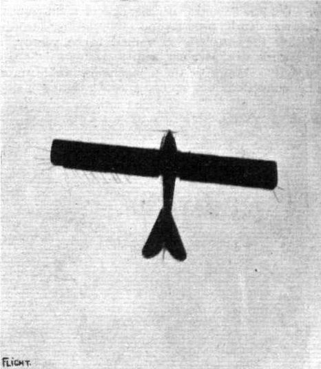
View from below of the Albatros in flight.
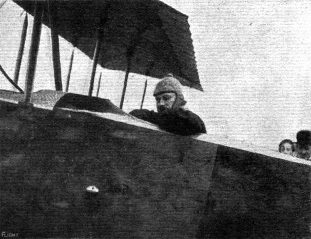
Herr Thelen in the cockpit of the Albatros.
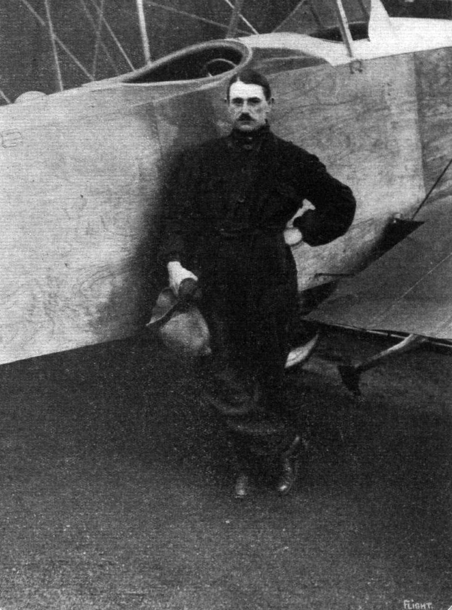
HERR THELEN.
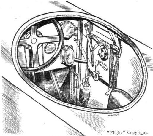
Pilot's cockpit on Albatros.
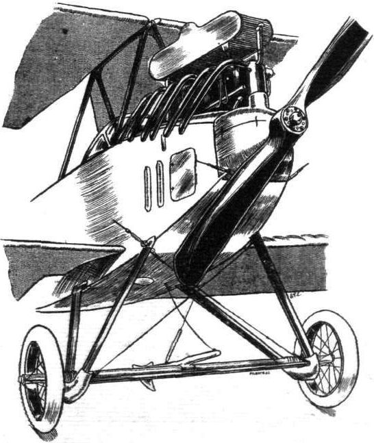
Chassis and engine of Albatros.

Detail of shock absorbing arrangement on Albatros.
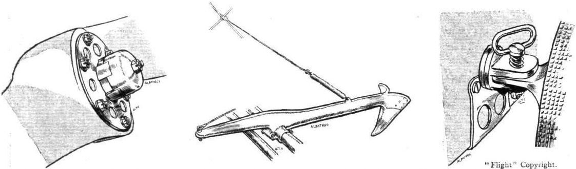
Left, method on Albatros of locking propeller on engine shaft; centre, the hand operated brake; and right, attachment of lower plane to fuselage.
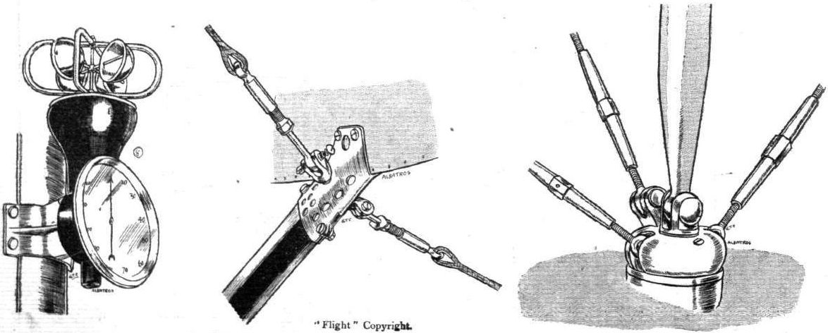
Left, the anemometer on the Albatros wfcich is mounted on one of inter-plane struts. Centre, a chassis detail, and right, attachment of inter-plane struts and cress bracing cables to main spars.
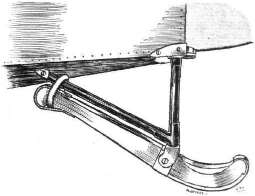
The tail skid of Albatros.
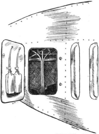
Oil and petrol cans mounted on engine inspection door of Albatros.
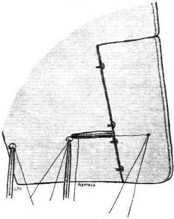
Aileron crank lever on Albatros.
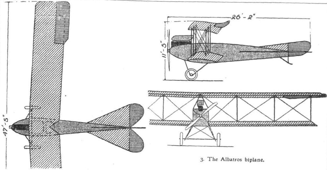
3. The Albatros biplane.

THE ALBATROS BIPLANE. - Plan, side and front elevations to scale.
Flight, September 25, 1914.
AIRCRAFT "MADE IN GERMANY"
WHICH MAY BE EMPLOYED AGAINST THE ALLIES.
4. The Albatros Seaplane
is similar to an earlier type of this firm's land machines. The body, which is of rectangular section, is very deep and narrow, and is placed a short distance above the lower main plane. The engine - a 100 h.p. Argus or a Mercedes of the same power - is placed in the nose of the body, and is entirely covered in. The radiator forms the extreme nose of the body, and the air passing through the radiator is allowed to escape through louvers in the side of the body. Behind the engine is the passenger's cockpit, whilst still further back, and some distance behind the trailing edge of the planes, is the pilot's seat. The two main floats, which are of the plain non-stepped type, are supported on very stout streamlined steel tubes. This machine is of the amphibious type, since it is fitted, in addition to the floats, with two wheels which may be raised clear of the water. A small tail float protects the tail planes against contact with the water. The main planes are set at a dihedral angle in addition to their backward slope, and ailerons are hinged to the outer ends of the upper plane.
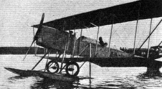
4. The Albatros Tractor seaplane.
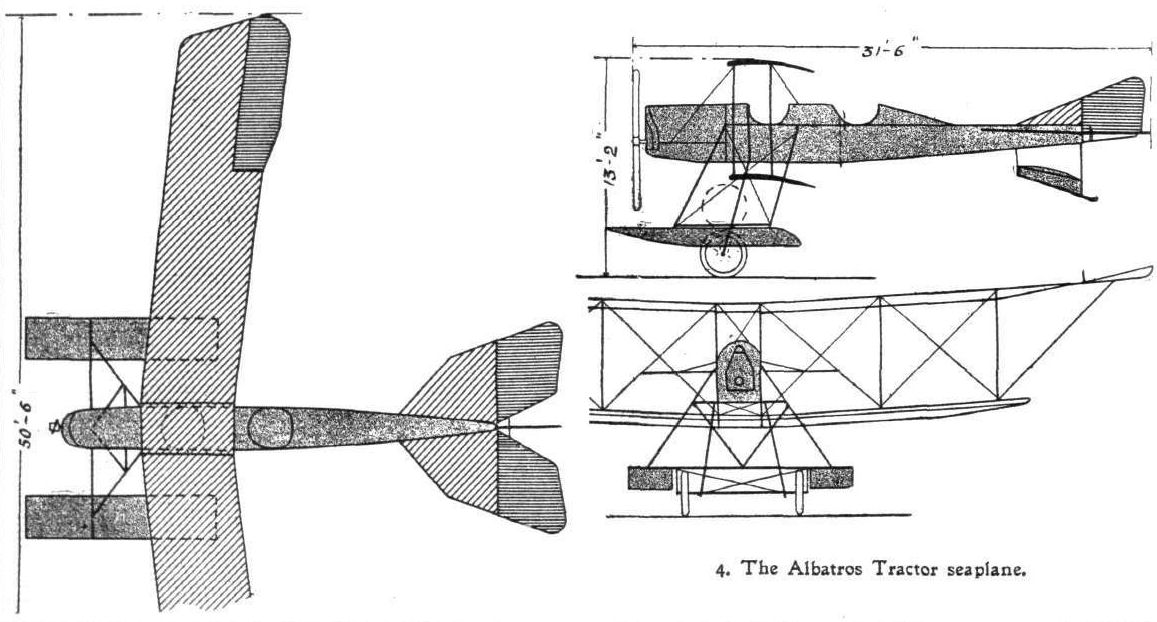
4. The Atbatros Tractor seaplane.
Flight, June 5, 1914.
THE PRINCE HENRY CIRCUIT, 1914.
MACHINES IN PRINCE HENRY CIRCUIT.
The Albatros Taube is characterized by a fuselage similar to that of the biplane with which our readers are already familiar through detailed descriptions in these columns. The wings are of the Taube type, and bracing is effected by a bridge girder structure of steel tubes under the wings. Provision has been made for folding the wings in a very short space of time. The chassis, which is also built of steel tubes, is very robust, and its different parts are standardised to facilitate interchange.
Flight, August 21, 1914.
AIRCRAFT "MADE IN GERMANY"
WHICH MAY BE EMPLOYED AGAINST THE ALLIES.
4. The Albatros Taube
is characterised by a. fuselage similar to that of the biplane. The wings are of the Taube type having back-swept upturned tips, and there is the usual girder structure forming the lower wing bracing as in nearly all Taube monoplanes. It consists of a steel tube running parallel to the wing spars and placed some distance below the wing to which it is connected by a number of steel tube struts and diagonal cross bracing. Although offering a considerable amount of head resistance this type of construction is employed as it provides a structure of almost equal strength to that of a biplane. The stabilizer and elevator are formed by a single plane the front portion of which is rigidly attached to the fuselage whilst the rear part acts as an elevator by being flexed up and down. Steering is effected by means of two rudders, one above and one below the tail plane. Lateral control is maintained by flexing the upturned wing tips. Provision has been made for rapidly folding the wings for purposes of storage or transport. The chassis is similar to that of the biplane, the different parts have been standardised in order to facilitate interchange.
Flight, October 9, 1914.
AIRCRAFT "MADE IN GERMANY"
WHICH MAY BE EMPLOYED AGAINST THE ALLIES.
6. The Albatros Taube
Is of the type used in the Lake Constance Race in 1913. Its main planes are of the usual Taube type, being of Zanonia form. The body is of particularly good stream line form, having no sharp angles in its outline. Pilot's and passenger's seats are arranged in tandem as in the land machines, and just in front of the passenger is mounted a 100 h.p. Mercedes engine. The tail planes are similar to those fitted on the Albatros biplanes, and consist of a horizontal stabilising plane, to which is hinged the divided elevator, and of vertical fins above and below the body, to which is hinged the rudder. As is the case with the majority of German seaplanes, this machine is amphibious, being fitted with a combined land and water chassis. The two wheels, which are placed between the floats, can be raised clear of the water and lowered again at will by means of a lever in the passenger's cockpit. The two floats, which are of the single stepped type, are built up of two skins of mahogany over an ash framework and are carried on a structure of streamlined steel tubes.
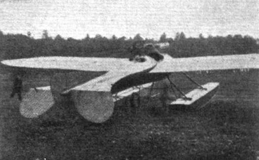
6. The Albatros Taube.
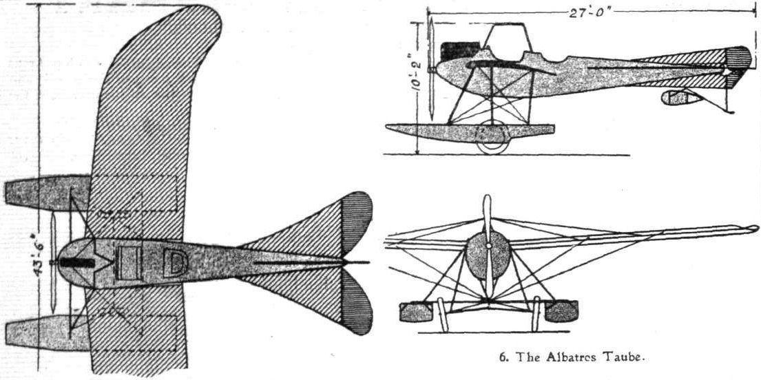
6. The Albatros Taube.
Flight, October 9, 1914.
AIRCRAFT "MADE IN GERMANY"
WHICH MAY BE EMPLOYED AGAINST THE ALLIES.
7. The Albatros Tractor Seaplane
is practically identical with the land machines, with the exception of course that floats are fitted. These, which are of the non-stepped type, are sprung from the chassis struts by rubber shock absorbers which are enclosed in streamlined casings, partly to reduce head resistance and partly in order to protect them against the effect of salt water. The body, which is of rectangular section, is covered with three-ply wood in the same manner as the land machines flown by Thelen at Hendon some time ago. The seats are arranged in tandem, the pilot sitting at the rear, from where he obtains a good view in a downward direction further enhanced by leaving the inner portion of the trailing edge of the lower plane uncovered. In front of him, and protected by a mica wind-screen, is the passenger, situated immediately behind the 160 h.p. Mercedes engine, which is mounted in the nose of the body. Long exhaust pipes carry the exhaust gases away over the side of the body. The weight of the tail planes is taken when the machine is at rest by a peculiarly shaped float mounted underneath the rear portion of the body. The wheels shown in the illustration do not form part of the chassis, but are part of a transport trolley attached to the floats by strong steel straps.
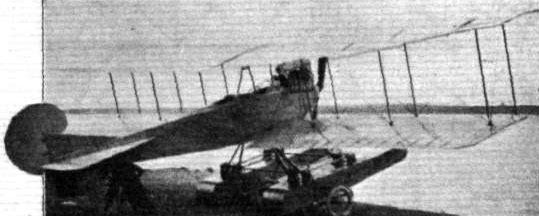
7. The New Albatros Tractor seaplane.
Flight, August 21, 1914.
AIRCRAFT "MADE IN GERMANY"
WHICH MAY BE EMPLOYED AGAINST THE ALLIES.
3. The Albatros Biplane
is already familiar to our readers through a detailed description of the machine flown by Thelen at Hendon some time ago. The main planes follow, more or less, orthodox lines, and it is the constructional detail work more than any great originality in the general design that has made these machines so popular among German military pilots. The fuselage, which is of rectangular section, is built up without the use of any internal cross-bracing, the necessary rigidity being provided by the three-ply wood covering screwed on to the longerons of the fuselage. The seats are arranged in tandem, the passengers sitting immediately behind the engine. In the nose the covering round the engine is aluminium sheeting, and inspection doors on each side give easy access to the interior. The chassis, built of steel throughout, is of a very simple and yet substantial type, without skids, but a small pivoted skid protects the tail planes against contact with the ground. A 100 h.p. Mercedes is fitted, and for ordinary purposes sufficient fuel is carried for a flight of about four hours' duration, although by substituting larger tanks this period can be considerably increased, as shown by some of the recent duration flights made on these machines in Germany.
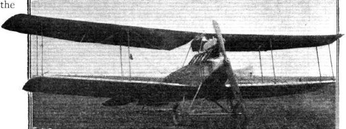
3. The Albatros biplane.
Flight, February 14, 1914.
FOREIGN AVIATION NEWS.
Beating the World's Duration Record.
SPLENDID as was Langer's duration record, to which reference was made in FLIGHT last week, it was completely put in the shade by the performance by Ingold on a Pfeil biplane on Saturday last. Setting out from Mulhausen at 7.35 a.m., he landed at 11.55 p.m. near Fuerstended, so that he had been in the air for 16 hours 20 mins., during which he covered a distance of about 1,700 kiloms. Langer's record was 14 hours 7 mins. The Aviatik-Pfeil biplane used is fitted with a 6-cyl. Mercedes motor.
Flight, June 5, 1914.
THE PRINCE HENRY CIRCUIT, 1914.
MACHINES IN PRINCE HENRY CIRCUIT.
The Aviatik Biplane follows standard lines as regards the general arrangement of its component parts. It is of the "Arrow" type, now so popular in Germany, and has an all-enclosed fuselage. The chassis is of modern simple type without skids. Pilot's and passenger's seats are arranged tandem fashion, the pilot occupying the rear seat.
Flight, August 28, 1914.
AIRCRAFT "MADE IN GERMANY"
WHICH MAY BE EMPLOYED AGAINST THE ALLIES.
7. The Aviatik Tractor Biplane
is of the arrow type, although its wings only possess a comparatively slight sweep back. As in other biplanes of this type, the upper main plane is straight as viewed from in front, while the lower plane is given a slight dihedral angle. The rectangular section fuselage is of streamline form, but is deeper at the stern than is usually the case. The turtle back does not extend over the entire length of the fuselage, but finishes off just behind the pilot's seat, which is considerably farther forward than in other arrow type machines, owing, no doubt, to the fact that the wings are so nearly straight. In front is the passenger's seat, between which and the engine are the fuel tanks with sufficient fuel for a 4-hours flight. Either Argus or Mercedes 100 h.p. engines may be fitted. The radiators are mounted on either side of the fuselage. The chassis is of the usual simple type, differing, however, from others in that the struts do not form an angle at their lower extremities, but are secured to two short skids from which is slung the tubular axle. The tail planes are protected against contact with the ground by a short swivelling skid. With full load on board, including pilot and passenger and four hours' fuel, the machine does just over 60 m.p.h., and climbs 1,000 metres (3,281 ft.) in 15 minutes.

Herr Karl Ingold and his 100 h.p. Mercedes Aviatik-Pfeil biplane on which he made his recent record flight.
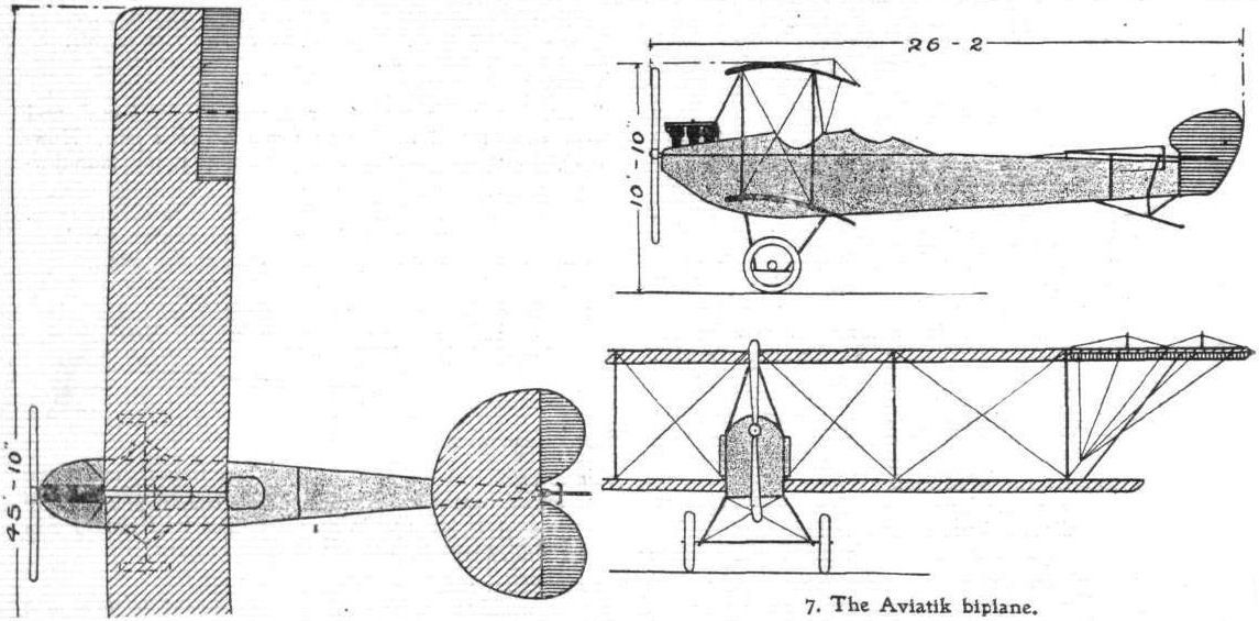
7. The Aviatik biplane.
Flight, August 28, 1914.
AIRCRAFT "MADE IN GERMANY"
WHICH MAY BE EMPLOYED AGAINST THE ALLIES.
7. The Aviatik Tractor Biplane
is of the arrow type, although its wings only possess a comparatively slight sweep back. As in other biplanes of this type, the upper main plane is straight as viewed from in front, while the lower plane is given a slight dihedral angle. The rectangular section fuselage is of streamline form, but is deeper at the stern than is usually the case. The turtle back does not extend over the entire length of the fuselage, but finishes off just behind the pilot's seat, which is considerably farther forward than in other arrow type machines, owing, no doubt, to the fact that the wings are so nearly straight. In front is the passenger's seat, between which and the engine are the fuel tanks with sufficient fuel for a 4-hours flight. Either Argus or Mercedes 100 h.p. engines may be fitted. The radiators are mounted on either side of the fuselage. The chassis is of the usual simple type, differing, however, from others in that the struts do not form an angle at their lower extremities, but are secured to two short skids from which is slung the tubular axle. The tail planes are protected against contact with the ground by a short swivelling skid. With full load on board, including pilot and passenger and four hours' fuel, the machine does just over 60 m.p.h., and climbs 1,000 metres (3,281 ft.) in 15 minutes.
Flight, August 28, 1914.
AIRCRAFT "MADE IN GERMANY"
WHICH MAY BE EMPLOYED AGAINST THE ALLIES.
8. The New Aviatik Biplane
is, for a German machine, very small and light and of the tractor type. Like the larger machines it is of the Arrow type, having its main planes sloping slightly backward. The upper and lower planes are connected by steel tube struts of streamline section, and a cabane of the monoplane type serves as an anchorage for the centre portion of the top plane. The fuselage, which is of rectangular section, is more on the lines of English machines, probably on account of the fact that instead of the vertical engine with which German machines are usually fitted, it has a rotary engine - a 114 h.p. Oberursel motor, mounted in the nose of the fuselage between double bearers. Pilot and passenger sit one behind the other, the passenger in front. Between him and the engine are carried, inside the fuselage, the petrol and oil tanks. The chassis is of the simple type which has now gained such popularity among German constructors, and consists of two "Vs" of streamline section steel tubes. The axle rests in the angle between the tubes, and is sprung by rubber shock absorbers.
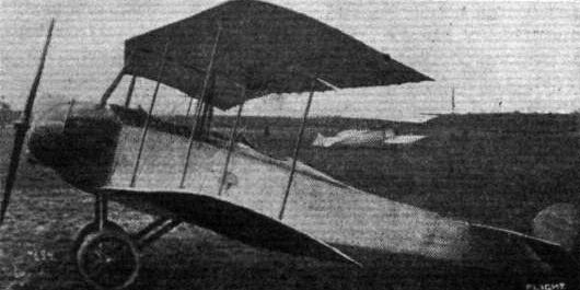
8. The new Aviatik biplane.
Flight, October 9, 1914.
AIRCRAFT "MADE IN GERMANY"
WHICH MAY BE EMPLOYED AGAINST THE ALLIES.
8. The Aviatik Seaplane
is a tractor biplane of the usual fuselage type. The main planes, of which the upper one is of slightly larger span than the lower one, are of rectangular plan form, and are separated by four pairs of steel tube struts. The two halves of the upper plane are joined to a monoplane type of cabane, the four tubes of which are secured to the upper longitudinals of the body. In the nose is mounted the 190 h.p. Argus motor, access to which is gained through inspection doors in the aluminium covering of the front portion of the body. Further back, and on each side of the body, are mounted the two radiators. Pilot and passenger sit behind one another, tandem fashion, the pilot occupying the rear seat. A large main float is carried on a very simple structure of steel tubes, and the lateral stability of the machine when on the sea is increased by two smaller auxiliary floats supported on steel tubes from the lower main plane.
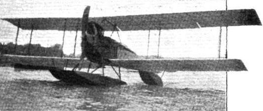
Flight, January 10, 1914.
THE D.F.W. BIPLANE.
If the D.F.W. biplane may be considered as being representative of German aeroplane construction - and the prominent position occupied by the German Aircraft Works (Deutsche Flugzeug Werke), of Lindenthal, near Leipzig, certainly justifies this assumption - aeroplane construction in Germany has made tremendous strides during the last year or so. In this country, steel construction has been comparatively little employed, and if for no other reason this new arrival to our shores would be of great interest. There are, however, a great number of other things to attract one's attention, both as regards design and new details incorporated in the construction.
Like the majority of German machines, this biplane is of the tractor type, with the weights of engine and pilot situated comparatively far apart. The engine, a 100 h.p. six-cylinder Mercedes, is mounted on stout ash bearers in the front portion of the fuselage. The radiator in conjunction with the lower front portion of the fuselage forms a very good entry for the air, which is allowed to flow along the gently tapering sides until it meets again behind the pointed stern.
Constructionally the fuselage is built up of three tubular longerons connected by a system of three-ply wood cross-members, a construction which, apart from being very strong, possesses a certain amount of elasticity, which greatly minimises danger of distortion due to shocks. Steel wires running longitudinally and supported on the cross-members serve to form the streamline shape of the lower portion of the fuselage, whilst a turtle back of three-ply wood runs from a point behind the pilot's seat to the rudder post. An aluminium cover, black enamelled, extends from the engine housing to a point just to the rear of the pilot's seat. This cover is attached to the upper longerons by means of ordinary bonnet fasteners, and can be easily removed for the purpose of examining the controls, &c. In front of the pilot's and passenger's seats this cover is swept slightly upwards in order to deflect the air and thus form a wind-screen for the protection of the occupants.
The two seats are arranged tandem fashion, the pilot occupying the rear seat, from where he has, due to the position well to the rear of the trailing edges of the wings, a practically unrestricted view in all directions. The passenger's seat is situated sufficiently far forward to enable him to look over the leading edge of the lower plane, and thus has a good view in a downward and forward direction, while an unobstructed view straight downwards is obtained by cutting away the trailing edge of the lower plane in the vicinity of the fuselage. Mounted on a very neat dash in front of the pilot are an uncommonly complete set of instruments, not the least interesting of which is a very small, compact Bosch self-starter, which is in reality a small dynamo, hand operated, by means of which the pilot can start his engine with one or two revolutions of a small handle, without any necessity of swinging the propeller. This is, of course, on the assumption that there is sufficient gas in the cylinders, which seems to be always the case with the excellent Mercedes engine, for on the twenty odd times that we have seen the engine started the device never failed to work.
The controls are of the usual type, consisting of a vertical tubular column on which is mounted a hand-wheel, the rotation of which operates the ailerons, whilst the to-and-fro movement actuates the elevator. The rudder is controlled by means of two foot-pedals similar to those used on motor cars. Two sets of controls are provided, so that either pilot or passenger may take control of the machine at any time. If desired the passenger's controls may be easily put out of action.
Between the engine and the passenger's seat is a large petrol tank containing about 50 gallons of petrol, which is fed to the two carburettors by gravity. A smaller emergency tank, containing an additional supply of about four gallons, is slung underneath the top plane. Six exhaust pipes project through the fuselage covering on the right hand side of the machine, and they are made of sufficient length to ensure that no exhaust gases are blown back in the faces of the pilot and passenger. In order to keep these pipes cooler they are not exactly in line, the front one projecting more outwards from the body than the rear one so that the air is allowed to flow freely round all of them. A gauze bonnet is fitted over the engine so as to allow of easy inspection.
The main planes, which have a very decided slope backwards, are built up of ash spars of I section with side pieces of poplar, over which are built the ribs, which have webs of three-ply wood and flanges of lime wood. The upper plane is straight - that is to say, it has no dihedral angle - whereas the lower plane has a dihedral of four degees. Six pairs of struts connect the main planes, and these struts are unusual in that they are hinged in the centre so that they can be folded, thus allowing the two planes to be laid flat against one another, when the machine is dismantled. This is accomplished without in any way interfering with the cross bracing of the planes, so that these can be erected again without any adjustment whatever. The top plane has a considerably larger span than the lower one, and the two extensions are supported, when the machine is on the ground, by steel tubes running from the upper wing tip to the lower ends of the outer pair of plane struts. For accommodation in a small hangar these two extensions of the top plane can be easily folded down, thus reducing the overall span to about 40 feet. Along the leading edge of the wings we noticed some little fittings, the purpose of which evidently is to allow the wings to be rolled along the floor of the hangar without the necessity of lifting them, an operation which, if not carefully carried out, is apt to strain the wings. To the rear spar of the top plane are hinged two ailerons, which are set at a negative angle of incidence normally, and thus serve the same purpose, to a certain extent, as the upturned wing-tips of the Etrich and Handley Page machines. There seems, however, to be very little necessity of using these ailerons, for during a flight of about twenty minutes' duration on which we accompanied the D.F.W. Company's chief pilot, Herr Roempler, a careful observation of the ailerons revealed the fact that the pilot did not have to move them once during the whole flight. We did a steeply-banked right-hand turn only a short height above the trees just outside the track at Brooklands, where gusts and remous are known to be practically always prevalent, and we fully expected that here at least the ailerons would be called into play, but evidently there was no necessity to do so, for after completing the turn the machine gradually came back to an even keel without the slightest movement of the ailerons. Another thing noticed was that on making a turn the machine seemed to bank automatically to just the right degree, for we did not feel the tendency to lean towards the higher side generally experienced on a machine where warp or ailerons are employed to increase or counteract the bank; the amount of banking must, therefore, have been at least fairly correct for the particular speed and curve.
On landing, the good qualities of the chassis were demonstrated, for on running into a small mound in the ground the machine simply bounced slightly and alighted again without any shock. The chassis consists of two pairs of U-shaped steel tubes held rigid by a pyramid of four shorter and thinner steel tubes having their apex underneath the lower main plane where the keel of the fuselage rests on it, and secured to the U-tubes by steel clips. The chassis tubes are attached to the upper longerons by clips and bolts passing outside the tubes, which are therefore not weakened by piercing. Each of the two pairs of wheels is mounted on a short tubular axle, and sprung by means of rubber shock absorbers. Coil springs on each side provide for a slightly sideways travel of the machine on alighting. Instead of the usual radius rods, short stranded cables are used to keep the wheels in their normal position.
In order to provide a certain amount of speed variation the angle of incidence of the tail plane can be altered while the machine is in flight. The method of doing this is illustrated by one of the accompanying sketches. The tail plane, which is pivoted round a transverse steel tube in the stern of the fuselage, is divided into two halves, and does not fit tightly on to the sides of the fuselage, sufficient space being provided to allow of the upward and downward movement of the tail plane. A short tubular axle, working in bearings in the sides of the fuselage, carries two short crank levers, which work in slotted steel plates on the tail plane. On this axle is mounted a sprocket wheel, from which a short length of chain and stranded cables run to an autoloc wheel mounted on the outside of the fuselage just behind the pilot's seat. By rotating this wheel the axle, which carries the cranks, is revolved, and the front of the tail plane moves up or down according to the direction in which the handwheel is rotated. To the trailing edge of this tail plane is hinged the elevator, which is of the undivided type. On top of the fuselage is mounted a small vertical fin, which has hinged to its trailing edge the rudder. Leather edgings around all these hinges allow of easy inspection of the hinges, and in a similar way the fabric with which the fuselage is covered can be removed by undoing the lacing. A short rubber-sprung tail skid is pivoted below the tail planes. Stranded cables are used throughout for the wing bracing,
The weight of the machine empty is 1,460 lbs. and its speed is in the neighbourhood of 68 miles per hour. With a supply of fuel sufficient for seven and a half hours' flight, and with pilot and passenger, the machine climbs about 300 ft. per minute, and its gliding angle 1 in 8.5. The machine appeared to require a comparatively long run before taking the air, but Herr Roempler. contends that there is no reason for taking a machine off too soon provided there is room enough to give it a longer run, and when required the machine will, we understand, get off in under 50 yards. Mr. Cecil E. Kny who is the designer and manager of the German Aircraft Works, intends either to erect shops for building the machines in this country, or else to arrange with some large armament firm to build them under licence.
Flight, August 28, 1914.
AIRCRAFT "MADE IN GERMANY"
WHICH MAY BE EMPLOYED AGAINST THE ALLIES.
10. The D.F.W. Arrow Biplane
is already familiar to our readers from descriptions with scale drawings and sketches which have appeared in our columns. Two machines of this type have been flying at Brooklands for the past year or so, and there is no necessity to go into a detailed description. Suffice it to say that they are steady, reliable machines, if somewhat slow, and as they are built of steel practically throughout they stand up to very rough usage.
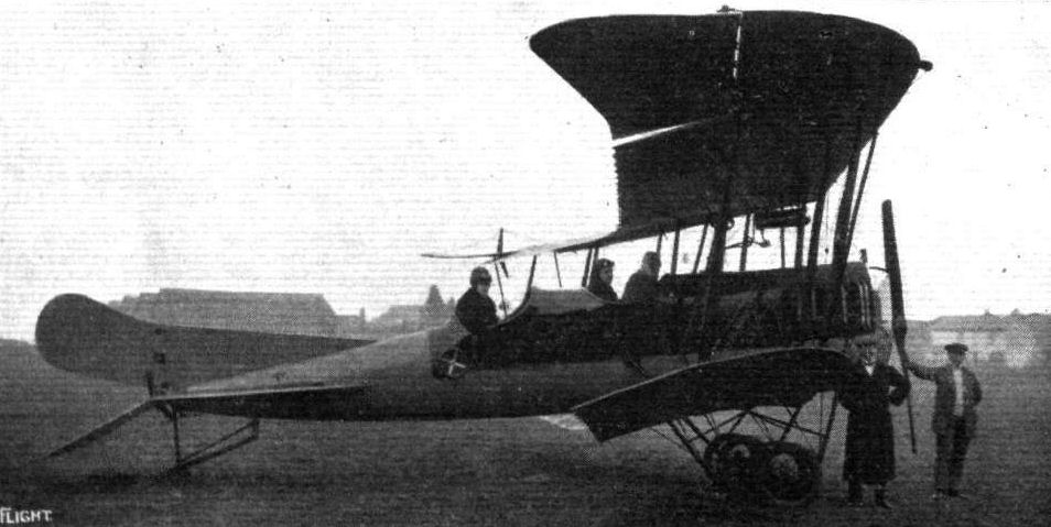
The D.F.W. biplane, as seen from the side.

The D.F.W. biplane from the front.
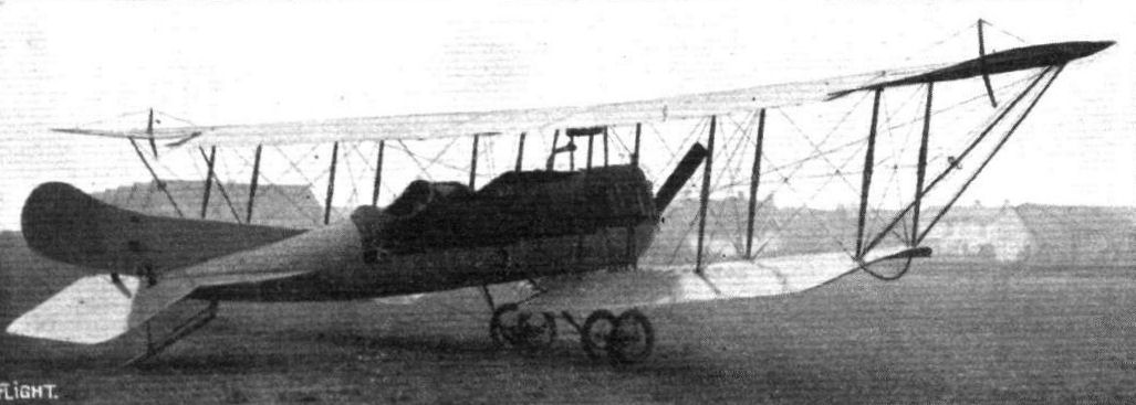
THE D.F.W. BIPLANE. - A three-quarter view from the back.
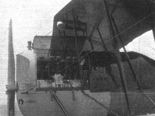
The front part of the D.F.W. biplane, showing the engine in place.
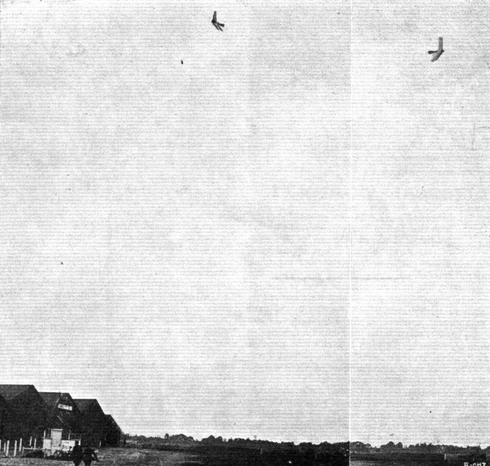
Some fine speciment of banking on the 100 h.p. D.F.W. all-steel Arrow biplane, when being flown recently by Lieut. C. H. Collet, of the Naval Wing of the R.F.C. at Brooklands.
Lieut. Collet, R.N.A.S., who took such a prominent part in the air raid on the Zeppelin sheds on Tuesday, will be remembered as doing some notable flying at Brooklands. Above we give a couple of photographs showing him banking steeply on the D.F.W. all-steel Arrow biplane.
Lieut. Collet, R.N.A.S., who took such a prominent part in the air raid on the Zeppelin sheds on Tuesday, will be remembered as doing some notable flying at Brooklands. Above we give a couple of photographs showing him banking steeply on the D.F.W. all-steel Arrow biplane.
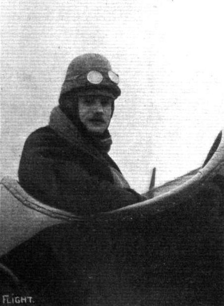
Herr Roempler, the skilful pilot of the D.F.W. aeroplane, now at Brooklands.
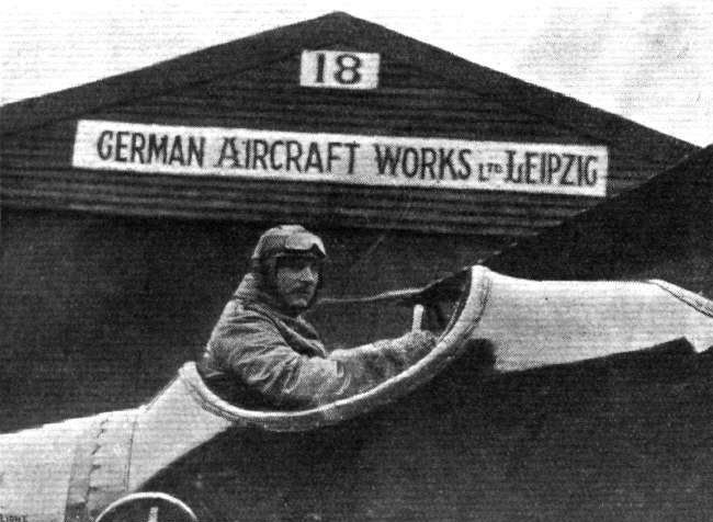
Lieut. Collet, of the Naval Wing of the R.F.C., in the pilot's seat of the 100 h.p. D.F.W. Arrow biplane, prior to his testing the machine on a long flight at Brooklands.

Lieut. C. H. Collet, who was to have piloted the British-built Beardmore D.F.W. tractor biplane in the Round Britain Race.

Sketch showing front part of fuselage and landing chassis of the D.F.W. biplane.
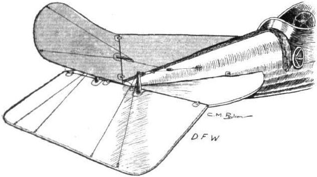
THE TAIL PLANES OF THE D.F.W. BlPLANE. - Note the wheel outside fuselage by means of which the angle of incidence of the tall plane may be altered during flight.

Sketch showing how angle of incidence of D.F.W. tail plane is altered.

Universal-joint on end of struts of D.F.W. biplane.
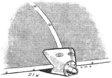
One of the "Domes of Silence" fitted on leading edge of D.F.W. wings to facilitate moving them about inside hangar.
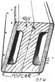
Section of D.F.W. wing spar.

Sketch showing how plane struts are hinged in the centre of the D.F.W. biplane.
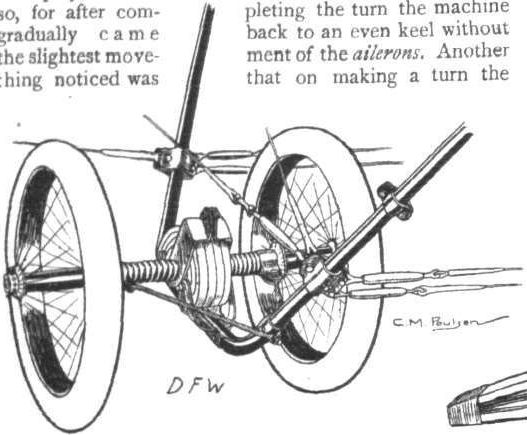
One side of landing chassis showing mounting of wheels.
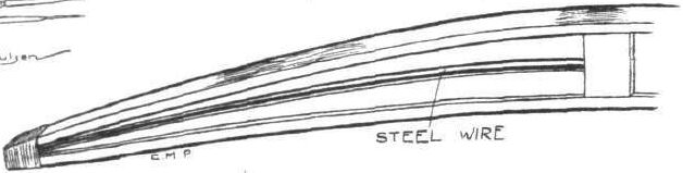
The flexible rear portion of the D.F.W. ribs.
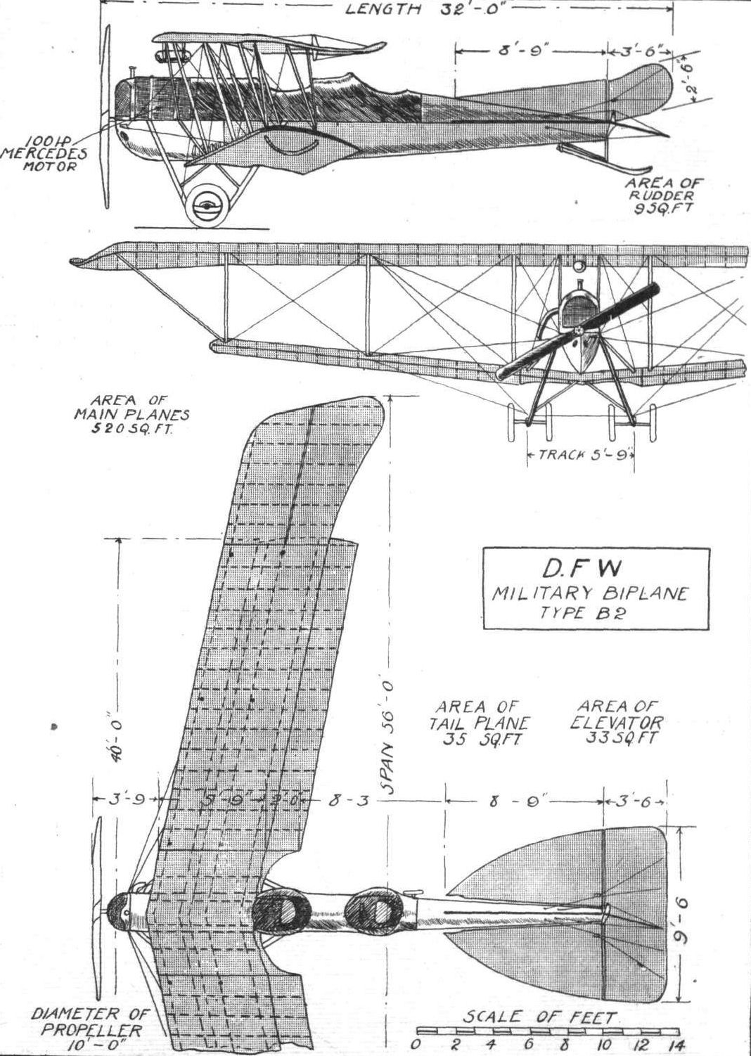
THE D.F.W. BIPLANE. - PIan, side and front elevations to scale.
Flight, October 9, 1914.
AIRCRAFT "MADE IN GERMANY"
WHICH MAY BE EMPLOYED AGAINST THE ALLIES.
9. The D.F.W. Flying Boat
is somewhat reminiscent, as regards the boat itself, of the Curtiss flying boat. The main planes, however, are entirely different from those of the Curtiss, being of the Arrow type. The lower main plane, in addition to its backward slope, is set at a very pronounced dihedral angle, partly to increase the lateral stability and partly to provide sufficient water clearance. The engine - a 100 h.p. Mercedes - is mounted well down in the hull and drives the propeller through bevel gearing. The two seats are arranged side by side inside the boat and just in front of the lower main plane. In front of the occupants the deck slopes steeply upwards so as to form a wind-screen, and on it is mounted the radiator. A step of comparatively great depth occurs approximately under the centre of gravity of the machine. Two small cylindrical floats protect the lower main plane against contact with the water.

9. The D.F.W. Flying Boat.
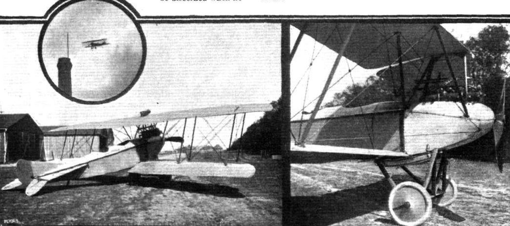
Two views of the 150 h.p. D.F.W. fast reconnaissance type biplane. Inset, the same machine in flight.
Flight, August 28, 1914.
AIRCRAFT "MADE IN GERMANY"
WHICH MAY BE EMPLOYED AGAINST THE ALLIES.
9. The D.F.W. Taube
is modelled on the lines of the Etrich Taube, at any rate as far as the shape and bracing of the wings is concerned. In addition to the usual cable bracing running to steel tube pylons above and beneath the fuselage the wings are further strengthened by a girder structure underneath. As these machines are now mostly used for school work, where strength to stand rough usage is of greater importance than low head resistance, this method of construction has much to recommend it, but for actual service they are somewhat slow and cumbersome.
Inside the rectangular section fuselage are arranged the two seats, in tandem, the pilot occupying the front one. The tail planes are of the usual Taube type, and consist of a horizontal plane, the front part of which is fixed whilst the rear portion acts as an elevator by being flexed up and down. Small rudders and triangular fins are fitted above and below the tail plane. A single central skid carried on four steel tube struts, of which the rear pair form the lower wing bracing pylon, is bent upwards in front to meet the fuselage under the front engine bearer. The wheels are carried on stub axles pivoted on the centre skid, and springing is effected by coil springs on telescopic steel tubes running to the upper longerons of the fuselage. The radiators are mounted on each side of the body. With a 100 h.p. Mercedes engine the D.F.W. Taube develops a speed of about 68 m.p.h.
Flight, August 28, 1914.
AIRCRAFT "MADE IN GERMANY"
WHICH MAY BE EMPLOYED AGAINST THE ALLIES.
11. The D.F.W. Military Biplane
differs considerably from the previous machine. In its general outline the fuselage is somewhat reminiscent of that of the Albatros biplane, with the exception that it tapers to a horizontal knife edge at the rear. Constructionally, it is quite different from the Albatros, however, being built entirely of steel. The struts and cross-members, which are, like the longerons, made of steel tubes, are secured to the latter by steel clips and acetylene, welding. The cross-bracing wires are secured to these steel clips, and the whole structure is one of great strength.
Behind the engine is the passenger's seat, while still further back is the pilot's cockpit. On a neatly-arranged dashboard in front of the pilot is mounted a very complete set of instruments.
The main planes differ from those of other Arrow-type biplanes, in that they are crescent-shaped. Both upper and lower planes are set at a dihedral angle, and there is a very pronounced "wash-out" of the angle of incidence towards the tips. Small slightly upturned ailerons are hinged to the tips of the upper plane. The chassis, like the rest of the machine, is built up of steel tubes, and is fitted with a brake similar to the one used on the Albatros biplane flown by Thelen at Hendon some time ago. With a 100 h.p. Mercedes engine the speed of the D.F.W. military biplane is 75 m.p.h., and she is credited with a climbing speed of 1,000 metres (3,281 ft.) in 5 mins.
THE NEW WORLD'S HEIGHT RECORD. - On the left, Oelrich standing by the record-breaking D.F.W. biplane, with its laurels, while on the right is a photograph of the barograph records duly attested.

11. The D.F.W. Military biplane.
Flight, August 28, 1914.
AIRCRAFT "MADE IN GERMANY"
WHICH MAY BE EMPLOYED AGAINST THE ALLIES.
12. The New Arrow-Type D.F.W. Biplane
is similar in several ways to the machine described above, chiefly as regards its fuselage. Its main planes, however, are not crescent-shaped, but are similar in form to those of the Beardmore D.F.W. entered for the Circuit of Britain, and which was described in our issue of last week. It is, like the latter machine, built entirely of steel. With a 120 h.p. Austro-Daimler engine it develops a speed of 85 m.p.h.
Flight, August 14, 1914.
THE "ROUND BRITAIN" MACHINES.
WE continue this week the illustrated description of the machines entered for the Circuit of Britain, with the British-built
Beardmore "D.F.W." Tractor Biplane,
which has been officially numbered 2 in the race. This machine is very similar to the one which established a new world's altitude record lately, by going up to a height of 26,568 ft.
Aerodynamically, the new D.F.W. biplane, constructed by the great British armament firm of Wm. Beardmore and Co., is chiefly remarkable for its good streamline fuselage and back-swept wings, and constructionally it is interesting on account of the fact that it is built of steel practically throughout. The fuselage, which is of rectangular section, is built up of four longerons converging towards the rear, where they meet the rudder post and forming, in the nose of the machine, an exceptionally good entry for the air. Struts and cross members made of steel tubing connect the four longerons,to which they are secured by means of acetylene welding. Diagonal cross-bracing completes the internal construction of the fuselage, which is of enormous strength, both as regards torsional and bending stresses. In the nose of the fuselage are the supports for the engine - a 120 h.p. British-built Beardmore Austro-Daimler - which are also made of steel. A hemispherical nose-piece of aluminium covers the front part of the body, the sides of which are covered with the same material up to the rear inter-plane struts. From this point to the stern the fuselage is covered with fabric laced on. An aluminium turtle back, made out of a single sheet, and having openings cut out for the engine and pilot's and passenger's cockpits, gives the top of the fuselage a particularly good streamline.
The main planes are, as we have already pointed out, of the back-swept or arrow type, and are in addition heavily staggered. The upper plane, which is of slightly greater span than the lower one, is made in two sections joining in the centre to a cabane of the monoplane type consisting of four struts of streamline steel tubes resting with their lower ends on the upper longerons of the fuselage and carrying at the top a horizontal member to which the two sections of the upper plane are secured. The inner ends of the spars of the lower plane are attached to the lower fuselage longerons by means of quick release devices.
Two pairs of steel tube struts on each side connect the main planes and by means of a special lever on the lower end of the struts these can be dismantled in a few minutes without interfering in the slightest with the bracing cables, so that no tuning up is necessary every time the machine is erected. The saving in time thus effected should be of the greatest value in a military machine.
Although the D.F.W. biplane is practically inherently stable laterally ailerons are fitted to the outer extremities of the planes. These ailerons are of triangular shape and have a negative or reversed camber. In normal flight they therefore are slightly negatively loaded, thus tending to increase the lateral stability of the machine. They are operated by means of cables passing round a drum on the control wheel. The latter is mounted on a vertical column, which is free to move in a forward and backward direction and to which are attached the elevator control cables. Steering is effected in the ordinary way by a pivoted foot bar.
The pilot's and observer's quarters are most comfortable in addition to affording an exceptionally good view in practically all directions. The seats themselves are made of aluminium and are of the bucket type, well upholstered with leather. The front seat is occupied by the observer, who is placed sufficiently far forward to be able to look out over the leading edge of the lower plane. The rear seat, on the other hand, is situated so far back that the pilot obtains an unrestricted view in a downward direction, which is of course of great advantage for alighting on the sea.
The tail planes are of the usual type and consist of a flat stabilising plane, the angle of incidence of which can be varied, although not during flight as in previous D.F.W. machines. To the trailing edge of the stabilizing plane is hinged the divided elevator, whilst to a continuation of the stern post is hinged the rudder. A small fixed vertical tail fin is fitted. A small egg-shaped metal float supports the tail planes when the machine is at rest.
For the race round Britain a float chassis was, of course, fitted, but a land chassis can be very quickly substituted should it be desired to use the machine for overland flying. The float chassis consists of two sets of struts made of streamlined steel tube. Both sets are in the form of the letter "M," as seen from the front, and the lower extremities of the struts are connected by a transverse tube to which the floats are attached. The upper ends of the front set of struts join the lower longerons of the fuselage immediately under the engine, whilst the rear struts join on to the lower longerons at the point where are attached the front spars of the lower main plane. The radiator occupies a rather unusual position in being mounted underneath the fuselage between the chassis struts. Bosch ignition and self-starter is fitted, so that it is possible to start the engine from the pilot's seat without any necessity for swinging the propeller. The weight of the machine empty is 1,500 lbs., and a speed range of 45 to 85 miles per hour is expected. It is anticipated that the climbing capabilities of the machine will be at the rate of 3,500 ft. in 6 mins. with a load of 125 lbs. in addition to pilot and observer and sufficient petrol, oil and water for six hours' flight.
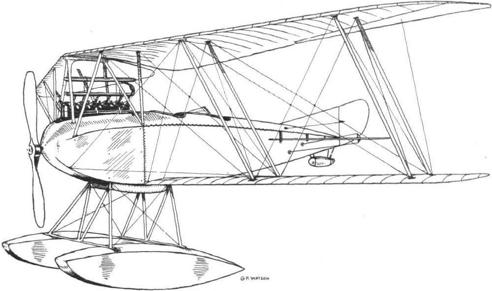
ROUND BRITAIN MACHINES. - No. 2. - The British-built Beardmore-D.F.W. (120 h.p. Beardmore-Austro-Daimler (British-built) engine) tractor biplane.

THE ROUND BRITAIN MACHINE No. 2. - Another sketch from behind of the British-built Beardmore D.F.W. tractor biplane.

THE "ROUND BRITAIN" MACHINES. - No. 2. The British-built Beardmore D.F.W. biplane. Plan and side elevations, to scale.
No photographs are known to exist of the 1914 Beardmore D.F.W. Circuit of Britain biplane. The three-view from Flight shows the proposed machine.
No photographs are known to exist of the 1914 Beardmore D.F.W. Circuit of Britain biplane. The three-view from Flight shows the proposed machine.
Flight, January 24, 1914.
THE EULER HYDRO-TRIPLANE.
SINCE Mr. A. V. Roe's experiments with a triplane which was later discarded for machines of the biplane type no successful triplane has, so far as we know, been constructed in this country. It is quite conceivable, however, that in time to come, when greater loads will have to be carried than is the case at present, the triplane type of machine will be revived, for constructional difficulties must of necessity put a limit to the span it is technically advisable to give a machine, and the triplane construction seems to be the easiest solution of the problem of obtaining the required larger lifting surface.
It is no doubt with this end in view, that the Euler hydro-triplane has been designed, and incidentally it is, to the best of our knowledge, the first successful hydro-triplane constructed.
From the accompanying photographs, it will be seen that the three main planes have an increasing span, that of the bottom plane being 8 m., that of the middle plane 10 m., whilst the top plane spans 14 m. The extensions of the uppermost planes can be folded down, thereby reducing the overall span by about 4 m. In order to diminish the interference of the planes without making the gap between them of excessive proportions the planes have been given a very pronounced stagger forward, a system which is finding increased favour with aeroplane designers generally.
The 100 h.p. 9-cylinder Gnome engine is mounted immediately above the centre plane, and is protected against the spray of water by the bottom plane. In order to keep the centre of gravity fairly low, the petrol tank has been placed down in the float or boat - for this machine is really a flying boat, having only one central float. Petrol is forced from this main tank to a small service tank near the engine, by means of compressed air contained in a special air reservoir in the rear part of the boat.
Carried on four tail booms attached to the rear spars of the top and bottom main planes respectively are the tail planes, which consist of a fixed tail plane to the trailing edge of which is hinged the elevator, and of a vertical rudder supported on a framework coming up from the rear part of the boat. This latter member is 7 rn. long and 1 m. wide, and is of the stepped type. The pilot's and passenger's seats are arranged tandem fashion, the pilot occupying the front seat. It will be noticed that in addition to the boat a landing chassis is fitted. When the machine is used on the water the wheels can be raised by the pilot, and lowered again if he desires to alight on land, so that the machine really belongs to the amphibious class of aeroplanes. The landing chassis is sprung by means of rubber shock-absorbers attached to the gunwales of the boat.
Flight, October 16, 1914.
AIRCRAFT "MADE IN GERMANY"
WHICH MAY BE EMPLOYED AGAINST THE ALLIES.
10. The Euler Triplane
is, we believe, the only successful hydro-triplane ever constructed. From the accompanying illustrations it will be seen that the three main planes have an increasing span, that of the bottom plane being 26 ft. 3 ins., that of the middle plane 33 ft., whilst the top plane spans 46 ft. The extensions of the top plane can be folded down, thereby reducing the overall span by about 13 ft. The staggering of the plane, as will be seen from the photographs, is very pronounced.
The 100 h.p. 9-cyl. Gnome engine is mounted immediately above the centre plane, and the lower plane, on account of the stagger, protects it effectively against water spray. Petrol is carried in a large tank placed down in the float or boat, and is forced from this main tank to a service tank near the engine by means of compressed air contained in a special air reservoir in the rear part of the boat.
Carried on four tail booms attached to the rear spars of upper and lower main planes respectively are the tail .planes, which consist of a fixed tail plane to which is hinged the elevator, and of a verticle rudder, supported on a framework coming up from the rear portion of the boat. The latter member, which is of the stepped type, is 23 ft. long and 3 ft. 4 ins. wide. The seats are arranged in tandem, the pilot sitting in front. In addition to the boat a land carriage is fitted, by means of which the machine can be started off land. For use over water the wheels may be raised above the boat, and can be lowered again from the pilot's seat should it be desired to alight on the shore. The landing wheels are sprung by means of rubber shock absorbers attached to the gunwales of the boat.
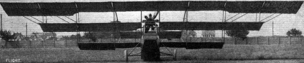
THE EULER HYDRO-TRIPLANE. - View from the front.

THE EULER HYDRO-TRIPLANE. - Three-quarter front view.
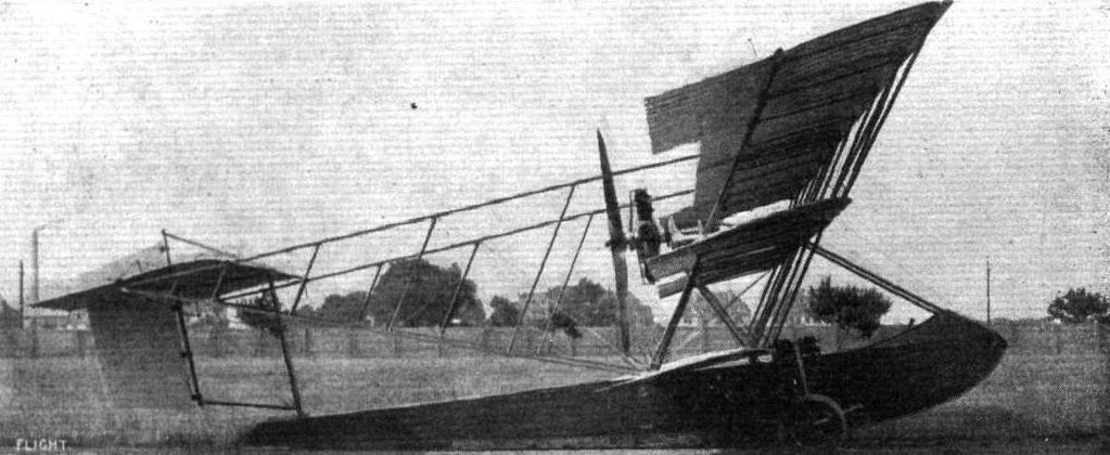
THE EULER HYDRO-TRIPLANE. - Side view.
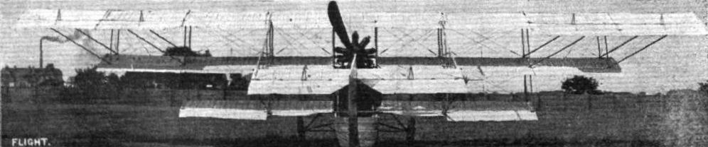
THE EULER HYDRO-TRIPLANE. - As seen from behind.
Flight, September 4, 1914.
AIRCRAFT "MADE IN GERMANY"
WHICH MAY BE EMPLOYED AGAINST THE ALLIES.
14. The Fokker Monoplane
is the only German machine of the monoplane type in which the back-swept wings have been employed, but the angle of incidence remains the same from root to tip. The fuselage takes the form of a short boat-like shell, in which are arranged the tandem seats, the pilot occupying the rear seat. Instead of attaching the wings to the fuselage they are secured to the chassis struts, and are set, in addition to their backward slope at a very pronounced dihedral angle. From the accompanying illustrations, it will be seen that the chassis is somewhat complicated and appears likely to become damaged in a heavy landing. Once in the air the machine is practically automatically stable, but as neither warp nor ailerons are fitted, it has been found very difficult to land in a wind. In consequence of this it is understood that the design has been modified considerably.
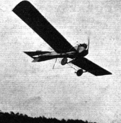
The latest Fokker monoplane with a 100 h.p. Mercedes engine, flying at the Johannisthal aerodrome.

Prince Bismarck, a grandson of the first Chancellor of the German Empire, passed the necessary tests for his pilot's certificate under the new regulations on January 17th on a Fokker monoplane at Schwertn in Mecklenburg. Prince Bismarck is only sixteen years of age, but gives promise of becoming a skilful aviator.
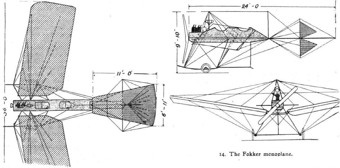
14. The Fokker monoplane.
Flight, October 16, 1914.
AIRCRAFT "MADE IN GERMANY"
WHICH MAY BE EMPLOYED AGAINST THE ALLIES.
13. The F.F. Seaplane
is an earlier type, and is, as the illustration shows, of the propeller or "pusher" type. Its main planes are of rectangular plan form, and the top plane has a considerable overhang, the weight of which is taken when the machine is at rest by steel tubes sloping down to the lower ends of the outer pair of interplane struts. The 135 h.p. engine is mounted in the rear of the nacelle, and in front of it, arranged tandem fashion, are the two seats. A wide central float of the single stepped type is fitted, and two small cylindrical floats are fitted to the tips of the lower main plans. The two wheels may be raised or lowered at will from the pilot's seat.
Flight, October 16, 1914.
AIRCRAFT "MADE IN GERMANY"
WHICH MAY BE EMPLOYED AGAINST THE ALLIES.
12. The F.F. Flying Boat
is an experimental machine specially built for the Warnemunde-Scandinavia Race. The hull of this machine takes the form of a short deep boat, which only extends back a short distance behind the trailing edge of the lower plane. The engine - a 150 h.p. Benz - is mounted in the rear portion of the hull, and drives through bevel gearing a four-bladed propeller, mounted approximately half way between the upper and lower main planes. Pilot's and passenger's seats are arranged side by side immediately in front of the leading edge of the lower plane, and a curved deck over the front portion of the boat forms a wind-screen for the occupants. As the boat does not extend sufficiently far back to carry the tail planes, these have been mounted on an outrigger consisting of four tail booms connected with struts and braced in the usual way by cross wiring. Ample water clearance is provided by setting the lower main plane at a pronounced dihedral angle, and as a precaution small floats are fitted to the lower wing tips.
Flight, October 16, 1914.
AIRCRAFT "MADE IN GERMANY"
WHICH MAY BE EMPLOYED AGAINST THE ALLIES.
11. The F.F. (Flugzeugbau Friedrichshafen) Seaplane
is a biplane of the tractor type, having a rectangular section body, and main planes which are straight as seen in plan but which are set at a dihedral angle. The engine - a 135 h.p. N.A.G. - is mounted in the nose of the body, and long exhaust pipes carry the exhaust gases down below the lower plane. Immediately behind the engine is the passenger's seat, whilst further back, to the rear of the trailing edge of the planes, is situated the pilot's seat. The two main floats are of the single stepped type, and are spaced comparatively wide apart in order to increase the lateral stability of the machine on the water. In previous models a single central float was fitted. A small float fitted under the rear part of the body takes the weight of the tail planes when the machine is at rest.
Flight, June 5, 1914.
THE PRINCE HENRY CIRCUIT, 1914.
MACHINES IN PRINCE HENRY CIRCUIT.
The Goedecker Monoplane is also of the Taube type, but in this machine the girder structure under the wings has been retained, no top bracing cables being fitted. The wing spars, as in all Goedecker machines, are steel tubes, and provision has been made for quick erecting and dismantling. By substituting a pair of floats for the wheels, this machine can be very quickly converted into a hydro.
Flight, September 4, 1914.
AIRCRAFT "MADE IN GERMANY"
WHICH MAY BE EMPLOYED AGAINST THE ALLIES.
15. The Goedecker Taube
is characterised by a three-wheeled chassis, and by the absence of any top bracing of the wings, the necessary rigidity being provided by a girder structure of steel tubes below the planes. The wing spars, as in all Goedecker machines, are steel tubes, and provision has been made for quick erecting and dismantling. By substituting a pair of floats for the wheels, this machine can be very quickly converted into a hydro. With a 100 h.p. Mercedes engine its speed is about 60 miles per hour.
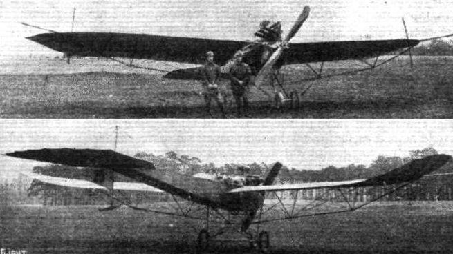
15. The Goedecker Taube.
Flight, June 5, 1914.
THE PRINCE HENRY CIRCUIT, 1914.
MACHINES IN PRINCE HENRY CIRCUIT.
The Gotha Taube is one of the neatest of the machines entered, especially as regards the engine and radiator mounting, which has been carried out in such a manner that the nose of the machine forms a very good entry for the air. The chassis is of the simplest form, and offers very little head resistance, as all the tubular chassis struts are of streamline section. The wheel axle is sprung from the chassis in such a manner that the wheels are free to move slightly sideways as well as in an upward direction.
Flight, September 4, 1914.
AIRCRAFT "MADE IN GERMANY#
WHICH MAY BE EMPLOYED AGAINST THE ALLIES.
16. The Gotha Taube
does not differ materially in its general lay-out from other monoplanes of this type. The shape and construction of the wings is practically the same as in others, but some slight alterations are to be found in the shape of the fuselage and landing chassis. The former, which is of nearly rectangular section, being slightly wider at the top than at the bottom, is fitted with a comparatively turtle back extending from the nose of the machine to a point some distance behind the pilot's seat. The chassis, although of a simple type, is very strong, and consists essentially of two pairs of steel tubes bent to form a U. A transverse tube connects the rear chassis struts a short distance above and behind the wheels, whilst two other tubes run from the lower ends of the front struts to the keel of the fuselage immediately under the engine. With an Argus or Mercedes 100 h.p. engine, the speed of the Gotha Taube is in the neighbourhood of 60 miles per hour. A feature which this machine has in common with a good many others of German origin, is the ploughshare-like brake operated from the pilot's seat. By means of this the machine can be brought to a standstill in a very short space on practically any ground.
17. The New Gotha Taube
is one of the neatest monoplanes of the Taube type, especially as regards the engine and radiator mounting. Bracing of the wings is effected as in ordinary monoplanes by stranded cables, the upper ones running to a steel tube pylon on top of the fuselage, and the lower ones being anchored to the chassis. This is of the simplest form, and offers very little head resistance, as all the tubular chassis struts are of streamline section. The wheel axle is sprung from the chassis in such a manner that the wheels are free to move slightly sideways as well as in an upward direction. For a Taube, the Gotha is unusually fast, developing, fitted with a 100 h.p. Mercedes engine, a speed of 74 miles per hour.
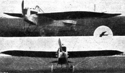
The Gotha Taube.

16. The Gotha Taube.

Krumsick on a Grade monoplane at the Munster aerodrome.
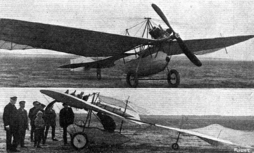
TWO OF THE LATEST GRADE MONOPLANES. - Top: The new 100 h.p. Grade monoplane, which is fitted with a 4-cyl. air-cooled Grade engine. In spite of the small number of cylinders this engine is said to be remarkably free from vibration. The oil consumption is 4/5 gal. per hour, and petrol consumption 7.7 gals, per hour. The speed of the machine is 75 m.p.h. Below: The 16-24 h.p. Grade monoplane, which weighs 265 lbs. only, and for which a speed variation of 50 per cent, is claimed.
Flight, June 5, 1914.
THE PRINCE HENRY CIRCUIT, 1914.
MACHINES IN PRINCE HENRY CIRCUIT.
The Halberstadt Taube is characterized by a monocoque fuselage covered with fabric inside and out. The main planes are of the usual Taube form, but the girder structure under the wings has been replaced by ordinary cable bracing top and bottom. For purposes of observation and in order to facilitate photography openings have been provided in the wings on each side of the observer's seat, and these openings are fitted with glass covers. The chassis consists of two pairs of V tubes from which is slung the tubular axle by means of rubber shock absorbers.
Flight, September 4, 1914.
AIRCRAFT "MADE IN GERMANY"
WHICH MAY BE EMPLOYED AGAINST THE ALLIES.
18. The Halberstadt Taube
is characterised by a monocoque fuselage, covered with fabric inside and out. The main planes are of the usual Taube form, but the girder structure under the wings has been replaced by ordinary cable bracing top and bottom. For purposes of observation, and in order to facilitate photography, openings have been provided in the wings on each side of the observer's seat, and these openings are fitted with glass covers. The chassis consists of two pairs of "V" tubes, from which the tubular axle is slung by means of rubber shock absorbers. The peculiar flexing tail plane found on most Tauben has been replaced in this machine by an ordinary flat non-lifting stabilizing plane, to the trailing edge of which is hinged the divided elevator. Mounted on top of the fuselage is a vertical fin of comparatively large area, to the trailing edge of which is hinged the rudder. Evidently the monococque type fuselage, and the absence of the usual girder structure below the wing, has reduced the head resistance enormously, for with a 100 h.p. Mercedes engine this machine is said to be capable of a speed of 92 miles per hour.
Flight, June 5, 1914.
THE PRINCE HENRY CIRCUIT, 1914.
MACHINES IN PRINCE HENRY CIRCUIT.
The Hansa Taube is practically identical with the Gotha Taube, with the exception of the wing bracing, which takes the form of a girder of steel tubes underneath the planes.
Flight, September 4, 1914.
AIRCRAFT "MADE IN GERMANY"
WHICH MAY BE EMPLOYED AGAINST THE ALLIES.
19. The Hansa Taube
differs in no way from the usual form. It has the familiar back-swept upturned wing tips, the flexing tail plane, and the divided rudder working half above and half below the fuselage. Seats are arranged in tandem, the passenger occupying the front seat immediately behind the engine. A short turtle back, extending from the nose to a point a short distance behind the pilot's seat, improves the streamline of the front portion of the fuselage. With a 100 h.p. Mercedes engine, the speed is 72 m.p.h.
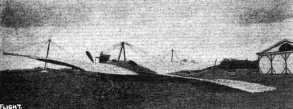
19. The Hansa Taube.
Flight, September 4, 1914.
AIRCRAFT "MADE IN GERMANY"
WHICH MAY BE EMPLOYED AGAINST THE ALLIES.
20. The Harlan Arrow Taube
combines the back-swept upturned wing tips of the ordinary Taube type monoplane, with the swept back wings of some of the Arrow biplanes. In addition to the backward slope of the wings, these are set at a very pronounced dihedral angle, and are braced in the usual way by means of a girder below the wings. Tail planes of the usual Taube type are mounted on the rear end of the very deep and narrow fuselage, the top of which is fitted with a turtle-back extending from the nose of the machine, back to the vertical tail fin. Openings have been cut out for the cylinders of the engine and for pilot and passenger, whose seats are arranged in tandem. The planes have been left uncovered for a distance of about 1 foot on each side of the fuselage, in order to provide a view in a downward direction. The chassis is of the wheel and skid type, consisting of a single central skid carried on steel tubes coming down from the lower longerons of the fuselage and swept upward in front to protect the propeller. To this skid are pivoted the stub axles which carry the wheels. Springing is obtained by rubber shock absorbers inside the fuselage, to which run steel tubes coming up from the wheel axles. With an Argus or Mercedes 100 h.p. engine, and with full load on board, this machine climbs 1,000 metres (3,281 feet) in 15 minutes.
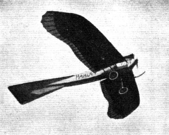
20. The Harlan Arrow Taube.
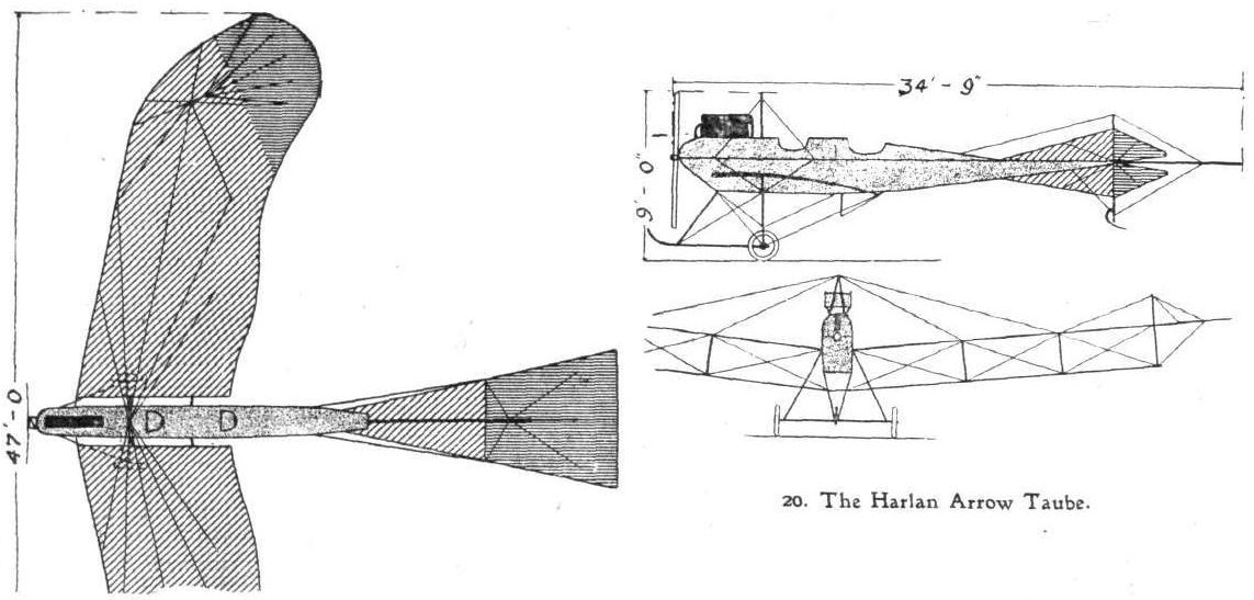
20. The Harlan Arrow Taube.
Flight, September 11, 1914.
AIRCRAFT "MADE IN GERMANY"
WHICH MAY BE EMPLOYED AGAINST THE ALLIES.
21. The Jatho Steel Taube.
THIS monoplane is, as the name implies, built throughout of steel; even the wing ribs are made of this material. The fuselage is nearly rectangular in section, the bottom being only slightly narrower than the top. It is constructed of steel tubes autogeneous welded. In front the longerons converge to form a very good entry for the air. Enclosed in this part of the body is the crank-case of the engine - a 100 h.p. Mercedes; whilst the cylinders project through the aluminium covering. Pilot's and passenger's seats are placed well down inside very roomy cockpits, where the occupants are protected against the wind. In front of the pilot is a dashboard with a very complete set of instruments, including barograph, tachometer, map case, watch, inclinometer, compass, &c. The petrol and oil tanks, which are placed low down in the fuselage, contain a supply sufficient for a flight of 7 hours' duration. As the speed of the machine is about 78 m.p.h it has a radius of action of something like 273 miles.
The wings are of the usual Zanonia form generally employed in monoplanes of the Taube type. The spars are made of steel tubes, and the ribs, as we have already mentioned, are also of steel. On each side of the fuselage part of the wings have been left uncovered in order to provide a better view in a downward direction.
The constructors of the Jatho steel Taube also build a racing type monoplane with a 150 h.p. engine, and a light sporting monoplane fitted with a Gnome motor.
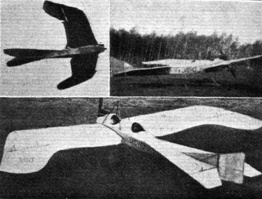
21. The Jatho Steel Taube.
Flight, June 5, 1914.
THE PRINCE HENRY CIRCUIT, 1914.
MACHINES IN PRINCE HENRY CIRCUIT.
The Jeannin Steel Taube is, as the name implies, built of steel practically throughout. The main planes are of the usual Taube type with back-swept, upturned wing tips. Wing bracing of the ordinary kind is employed, the upper bracing cables being taken to a top pylon, whilst the lower lift cables run to the lower extremities of the rear chassis struts. The divided axle, which is hinged to a short skid turned up in front to meet the nose of the fuselage, is sprung by means of telescopic tubes and rubber shock absorbers.
Flight, September 11, 1914.
AIRCRAFT "MADE IN GERMANY"
WHICH MAY BE EMPLOYED AGAINST THE ALLIES.
22. The Jeannin Steel Taube
is another all-steel machine. In wing form it differs but little from other monoplanes of its type, except that the girder under the wings has been in the latest models replaced by cable bracing. The passenger is situated immediately behind the engine, whilst just behind him is the pilot's seat. The engine - a 100 h.p. Mercedes - is mounted in the nose of the fuselage, and carries above it a radiator similar to that on the Albatros biplane. The chassis is of a very simple type, and consists of a short skid, carried on four streamline steel tube struts, and to it is hinged the divided axle, which is sprung by means of telescopic tubes running to the fuselage at the attachment to which are incorporated rubber shock absorbers.
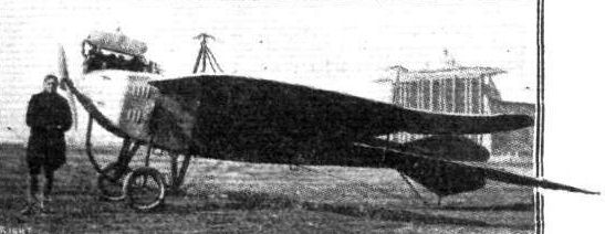
The Jeannin Steel Taube.
Flight, September 11, 1914.
AIRCRAFT "MADE IN GERMANY"
WHICH MAY BE EMPLOYED AGAINST THE ALLIES.
23. The Kondor Taube
resembles other monoplanes of this type in the shape of its wings and their bracing, but an attempt has been made to provide a better streamline fuselage. This member in the Kondor Taube is of circular section, with openings cut out of the top for the engine, passenger and pilot. The chassis is somewhat similar to that of the early Blackburn monoplane, and although appearing to be particularly strong would seem to offer a considerable amount of head resistance. The tubular axle is slung from the two short skids by means of rubber shock-absorbers. The flexing elevator forms a continuation of the fixed portion of the horizontal tail plane, and symmetrically divided rudders and vertical tail fins are fitted above and below the tail plane. Evidently the reduction of head resistance obtained by the circular fuselage is more than counteracted by the complicated chassis and wing bracing, for the speed of the machine with 100 h.p. Mercedes engine is only just over 60 miles per hour.
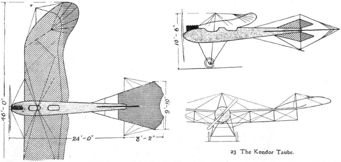
23. The Kondor Taube.
Flight, February 7, 1914.
FOREIGN AVIATION NEWS.
World's Record Duration Flight.
STARTING from Johannisthal on Tuesday at 8 a.m., Langer, on a biplane, made a flight which it is claimed beats the world's record of 13 hrs. 18 mins. made by Fourny on a biplane in September, 1912. After flying round the aerodrome for a couple of hours he went off and made cross-country flights, reappearing at Johannisthal in the evening, and landing at 10.15 p.m.
Flight, February 21, 1914.
FOREIGN AVIATION NEWS.
The Duration Record Nearly Beaten.
ALTHOUGH it failed by the narrow margin of 20 mins. a splendid attempt was made on the 11th inst. by Langer to regain the world's duration record. Starting from Johannisthal he flew to Konigsburg, and was well on his way back when he had to stop owing to his fuel supply giving out at Kreuz near Posen. He had then been in the air for 16 hours. Ingold's record, referred to in last week's FLIGHT, was 16 hours 20 mins.
Flight, September 11, 1914.
AIRCRAFT "MADE IN GERMANY"
WHICH MAY BE EMPLOYED AGAINST THE ALLIES.
24. The L.F.G. Arrow Biplane
has, as its name implies, wings of the back-swept type. The slope backwards of the wings of this machine is very pronounced. Whilst the upper main plane is straight as viewed from in front, the lower one is set at a very pronounced dihedral angle. The machine possesses a large amount of automatic stability laterally, and ailerons are fitted to the tips of the upper plane. At the rear of the rectangular section fuselage are carried the tail planes, which consist of a stabilising plane, to the trailing edge of which is hinged an undivided elevator, and of a balanced rudder mounted wholly on top of the tail plane. A skid formed by three steel tubes protects the tail planes against contact with the ground. Pilot's and passenger's seats are arranged tandem fashion, but very far apart, the passenger being placed immediately behind the engine, whilst the pilot's seat is situated well behind the main plane, about half-way along the fuselage. The chassis is built throughout of steel tubes bent round at the bottom to form short skids, from which is slung the tubular axle by means of rubber shock-absorbers. With a 100 h.p.. Mercedes engine, or an Argus motor of the same power, the speed of the machine is 60 miles per hour.
Flight, September 18, 1914.
AIRCRAFT "MADE IN GERMANY"
WHICH MAY BE EMPLOYED AGAINST THE ALLIES.
28. The Roland (L.F.G.) Arrow Biplane
shown in the accompanying photograph is the actual machine on which the German pilot, Bruno Langer, made some time ago a non-stop flight of sixteen hours' duration, a performance which clearly demonstrates the excellent qualities of both the machine and the 100 h.p. Mercedes engine with which it was fitted.
As a type the Roland biplane is in every way similar to other arrow biplanes, being characterised by the backswept wings, of which the lower one only is set at a dihedral angle, whilst the upper one is straight, as seen from in front. The fuselage is of the usual streamline form, and is rectangular in section. It is covered in front with aluminium sheeting, which has inspection doors cut in it to allow of easy access to the interior.
When used as a two-seater the passenger sits immediately behind the engine, and between him and the pilot's seat is mounted the petrol tank. In front of both occupants are celluloid windscreens mounted on an aluminium framework. For the 16 hours' flight a larger tank was fitted, whilst an additional supply of petrol was carried in the extra tank which may be seen in the photograph mounted just above the fuselage between the cabane struts.
The tail plane of the Taube type is mounted on top of the fuselage, and the rudder is hinged to the rear edge of a small triangular vertical tail fin. A skid formed by three steel tubes takes the weight of the tail planes when the machine is on the ground. The chassis is of the simplest type, consisting of only two pairs of streamline steel tube struts, each pair of which forms a V as seen from the side. The apices of the Vs are connected by a transverse horizontal tube on which rests the tubular axle slung from the angle between the chassis struts by means of rubber shock-absorbers.
FOREIGN AVIATION NEWS.
World's Record Duration Flight.
STARTING from Johannisthal on Tuesday at 8 a.m., Langer, on a biplane, made a flight which it is claimed beats the world's record of 13 hrs. 18 mins. made by Fourny on a biplane in September, 1912. After flying round the aerodrome for a couple of hours he went off and made cross-country flights, reappearing at Johannisthal in the evening, and landing at 10.15 p.m.
Flight, February 21, 1914.
FOREIGN AVIATION NEWS.
The Duration Record Nearly Beaten.
ALTHOUGH it failed by the narrow margin of 20 mins. a splendid attempt was made on the 11th inst. by Langer to regain the world's duration record. Starting from Johannisthal he flew to Konigsburg, and was well on his way back when he had to stop owing to his fuel supply giving out at Kreuz near Posen. He had then been in the air for 16 hours. Ingold's record, referred to in last week's FLIGHT, was 16 hours 20 mins.
Flight, September 11, 1914.
AIRCRAFT "MADE IN GERMANY"
WHICH MAY BE EMPLOYED AGAINST THE ALLIES.
24. The L.F.G. Arrow Biplane
has, as its name implies, wings of the back-swept type. The slope backwards of the wings of this machine is very pronounced. Whilst the upper main plane is straight as viewed from in front, the lower one is set at a very pronounced dihedral angle. The machine possesses a large amount of automatic stability laterally, and ailerons are fitted to the tips of the upper plane. At the rear of the rectangular section fuselage are carried the tail planes, which consist of a stabilising plane, to the trailing edge of which is hinged an undivided elevator, and of a balanced rudder mounted wholly on top of the tail plane. A skid formed by three steel tubes protects the tail planes against contact with the ground. Pilot's and passenger's seats are arranged tandem fashion, but very far apart, the passenger being placed immediately behind the engine, whilst the pilot's seat is situated well behind the main plane, about half-way along the fuselage. The chassis is built throughout of steel tubes bent round at the bottom to form short skids, from which is slung the tubular axle by means of rubber shock-absorbers. With a 100 h.p.. Mercedes engine, or an Argus motor of the same power, the speed of the machine is 60 miles per hour.
Flight, September 18, 1914.
AIRCRAFT "MADE IN GERMANY"
WHICH MAY BE EMPLOYED AGAINST THE ALLIES.
28. The Roland (L.F.G.) Arrow Biplane
shown in the accompanying photograph is the actual machine on which the German pilot, Bruno Langer, made some time ago a non-stop flight of sixteen hours' duration, a performance which clearly demonstrates the excellent qualities of both the machine and the 100 h.p. Mercedes engine with which it was fitted.
As a type the Roland biplane is in every way similar to other arrow biplanes, being characterised by the backswept wings, of which the lower one only is set at a dihedral angle, whilst the upper one is straight, as seen from in front. The fuselage is of the usual streamline form, and is rectangular in section. It is covered in front with aluminium sheeting, which has inspection doors cut in it to allow of easy access to the interior.
When used as a two-seater the passenger sits immediately behind the engine, and between him and the pilot's seat is mounted the petrol tank. In front of both occupants are celluloid windscreens mounted on an aluminium framework. For the 16 hours' flight a larger tank was fitted, whilst an additional supply of petrol was carried in the extra tank which may be seen in the photograph mounted just above the fuselage between the cabane struts.
The tail plane of the Taube type is mounted on top of the fuselage, and the rudder is hinged to the rear edge of a small triangular vertical tail fin. A skid formed by three steel tubes takes the weight of the tail planes when the machine is on the ground. The chassis is of the simplest type, consisting of only two pairs of streamline steel tube struts, each pair of which forms a V as seen from the side. The apices of the Vs are connected by a transverse horizontal tube on which rests the tubular axle slung from the angle between the chassis struts by means of rubber shock-absorbers.
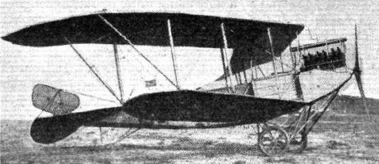
24. The L.F.G. Arrow biplane.

28. The Roland Arrow biplane.
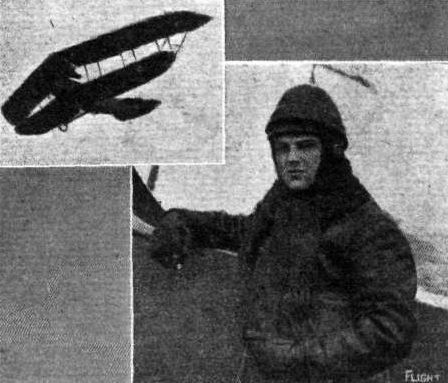
Herr Bruno Langer and his Roland-Pfeil biplane on which his big record was accomplished recently.
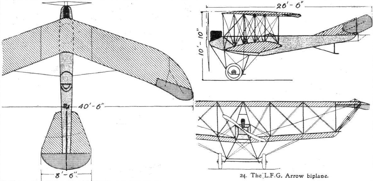
24. The.L.F.G. Arrow biplane.
Flight, June 5, 1914.
THE PRINCE HENRY CIRCUIT, 1914.
MACHINES IN PRINCE HENRY CIRCUIT.
The L.V.G. Biplane is similar to those in use by the German Government, with the exception that the capacity of the tanks has been increased in order to allow of completing all of the various stages of the course without intermediate landings. These machines are, as will be seen from the accompanying photographs, of the tractor type, and have fuselages of similar shape to that of the Albatros biplane which was described in these columns some time ago.
Flight, July 31, 1914.
THE DONATH SIGNAL MIRROR.
A METHOD of visual signalling in broad daylight by electricity has been recently introduced by Professor Donath of Berlin. The principle upon which it is based is that at extremely high temperatures the light transmitted from incandescent lamps is greatly augmented, without a corresponding increase in the consumption of current. In consequence thereof, however, the life of the lamps is much diminished; but as, in signalling, the duration of a flash is so short, this consideration is entirely negligible, as many messages can be transmitted before renewal of a lamp becomes necessary. It is stated by the Scientific American that the full equipment necessary for signalling by this means, including a battery for the supply of electric current, weighs only 11 lbs., and hence the device is especially adapted for use on aeroplanes and airships.
The signal mirror itself, which is similar in appearance to that used in the motor headlight, contains a small incandescent bulb fitted with a special filament, and is so designed that the lamp can be adjusted axially inside the parabolic mirror, as may be required in order to transmit a parallel beam of light. The mirror and lamp are carried on a handle which is held by the signaller, the switch controlling the supply of current to the bulb being mounted on the handle. Above the top of the lamp is a sighting tube through which the signaller observes the point with which he desires to communicate, and by depressing the button on the lamp handle he may send out flashes of varying duration - a short flash (say) of two seconds corresponding to a dot and a longer one, of about six seconds, to a dash. Thus, by the adoption of some conventional system or code, such as the Morse alphabet, communication with distant points can readily be made. Under normal conditions, it is said that signals may be transmitted over a distance of about four miles.
Flight, September 11, 1914.
AIRCRAFT "MADE IN GERMANY"
WHICH MAY BE EMPLOYED AGAINST THE ALLIES.
25. The L.V.G. Biplane
cannot, strictly speaking, be said to belong to the Arrow type, since, although the leading edge of its main planes slopes backwards, its trailing edge is straight as seen in plan. Both upper and lower main planes are set at a dihedral angle, and ailerons are fitted to the tips of the upper plane. The fuselage is of rectangular section, and resembles greatly that of the Albatros biplane. Pilot's and passenger's seats are placed close together, tandem fashion, the passenger sitting immediately behind the engine. The main weight is taken when the machine is on the ground by two wheels slung from the angle between two pairs of tubular chassis struts by means of rubber shock-absorbers. A short skid runs from the wheel axle to a point in front of the propeller, and two steel tubes running from the lower longerons of the fuselage immediately underneath the engine support the skid. A small wheel is incorporated in the angle between, the two front chassis struts, and serves to prevent the machine from turning over on her nose in case of a bad landing. This front portion of the chassis is chiefly used for school purposes, and may be removed in order to slightly increase the speed of the machine.
26. The New Type L.V.G. Biplane.
This machine differs, apart from dimensions, in minor details only from the one numbered 25. It is of slightly larger span, and head resistance has been reduced in various places, with the result that it is slightly faster than the older type. The engine fitted is a 100 h.p. Mercedes. It is worthy of note that the L.V.G. firm is one of the most important constructors of German military machines.

26. The new type L.V.G. biplane.

The L.V.G. biplane.

THE PRINCE HENRY CIRCUIT. - On the left, v. Thuna, the winner of the Kaiserprize, with Lieut, v. Kleist, his observer, and their 100 h.p. Mercedes biplane. On the right (from right to left), Prince Henry of Prussia, Messrs. Trutz, Geheimer Rat Buxenstein, Winter (K.F.A.C.). (From the Allgemeine Automobil Zeitung.)
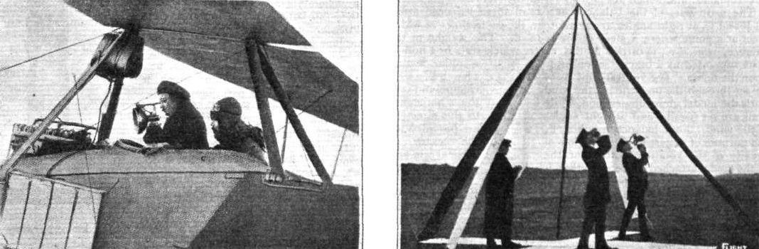
On the left, an observer in an aeroplane is shown in the act of transmitting a message to the ground, and on the right an observer is seen reading a message, while a signaller is standing by ready to reply thereto.
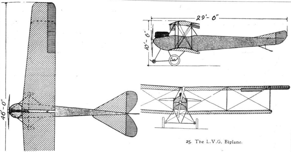
25. The L.V.G. biplane.
Flight, August 14, 1914.
AEROPLANE TYPES.
THE OTTO MILITARY BIPLANE.
THE Otto military biplane (type 1913), although somewhat on the lines of the Henry Farman military machines, actually differs from this type in many respects. First and foremost, it is constructed practically throughout of steel. Some considerable difference will also be found in the disposition of the engine and nacelle, the former being higher and the latter lower than obtains in Farman practice. Each of the main planes is built up on two spars, the front one of which is close to the leading edge, whilst the rear spar is placed some distance from the trailing edge. Both planes are given a slight dihedral angle and are attached to small, fixed, central pannels or sections. The upper plane has a greater span than the lower one, and large ailerons are fitted to the upper plane extensions only. Six pairs of steel struts separate the top and lower planes, and two pairs of triangular outriggers extend rearwards from the rear spars and carry the tail. The latter consists of a fixed stabilising plane, 3.2 sq. m. area, mounted on the top outriggers, and having two elevator flaps hinged to the trailing edge. Between the elevators is a vertical rudder hinged to the last strut joining the top and bottom outriggers. The nacelle, which is well streamlined, extends forward of, and below the lower plane, the pilot being seated in front with the passenger behind him; the front portion of the nacelle slopes upwards, forming a protection from the wind for the pilot. At the rear of the nacelle is a strong superstructure, carrying the engine high up, midway between the main planes. In front of the engine is the radiator, and above is the fuel tank. A portion of the trailing edges of the top and bottom planes is cut away to provide clearance for the propeller, which is 27 m. in diameter. The engine is a 6-cyl. 100 h.p. Argus, a type that has given very satisfactory results in Germany. The landing chassis is both strong and simple, consisting of two pairs of steel struts inclined outwards and forwards from the nacelle attached to two short skids, secured to which, by means of rubber shock-absorbers in the usual way, is a tubular steel axle carrying a pair of wheels. The control is of the usual Farman type, consisting of a central universally jointed lever actuating the ailerons by a side to side movement and the elevator by a to-and-fro movement; a horizontal foot-bar operates the rudder. The principal dimensions of this machine are :- Span, 14.8 m. (top), 9.5 m. (bottom); chord, 1.8 m.; supporting area, 40 sq. m.; overall length, 10.5 m.; speed, 110 k.p.h.
"VEE JAY."
Flight, September 18, 1914.
AIRCRAFT "MADE IN GERMANY"
WHICH MAY BE EMPLOYED AGAINST THE ALLIES.
27. The Otto Biplane
is one of the comparatively few propeller biplanes in use in Germany. It is somewhat reminiscent of the Henry Farman biplane, the upper main plane being of considerably greater span than the lower one. The nacelle, however, is of quite a different type from that of the Henry Farman, both as regards its shape and position. The upper longerons of the nacelle are attached to the spars of the lower main plane, and both upper and lower longerons taper to a point in the nose, whilst gradually flattening out towards the rear. To the tips of the upper main planes are hinged ailerons which are of greater chord at their tip than at the root, in order, no doubt, to render them more effective. The engine - a 100 h.p. Mercedes - is mounted a considerable distance above the lower plane, and drives a propeller situated behind the main planes, the trailing edges of which have been cut away in the centre to provide the necessary clearing. The tail planes are carried on an outrigger of steel tubes, and consist of a fixed stabilising plane, hinged to the trailing edge of which is the divided elevator, and of a partly balanced rudder. It will be noticed that, as in the Henry Farman, no vertical tail fin is fitted.
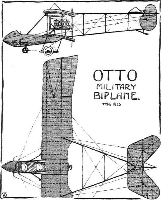
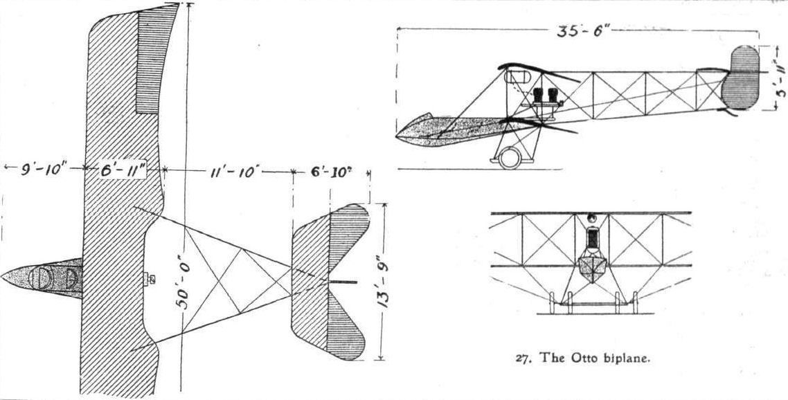
27. The Otto biplane.
Flight, June 5, 1914.
THE PRINCE HENRY CIRCUIT, 1914.
MACHINES IN PRINCE HENRY CIRCUIT.
The Rumpler Taube is a very compact business-looking machine. The upper wing bracing, it will be seen, is now effected by cables running to a pyramidal pylon of steel tubes, and the Zanonia form of wing has been retained. Instead of the usual flexing wing tips, ailerons are fitted. These, it should be noted, are hinged along an axis forming an angle with the transverse axis of the main planes.
Flight, September 18, 1914.
AIRCRAFT "MADE IN GERMANY"
WHICH MAY BE EMPLOYED AGAINST THE ALLIES.
29. The Rumpler Taube
differs from other monoplanes of the Taube type only in the shape of its fuselage and in the type of chassis fitted. The fuselage is very deep and narrow, and is fitted with the usual turtle-back, which is, however, considerably higher than is usually found. The chassis consists of two telescopic tubes fitted with coil springs and anchored to the upper longerons of the fuselage. At their lower extremities these telescopic tubes carry the wheel axle, and each of them is kept in place by two steel tubes running forward and backward to the lower longerons of the fuselage. The radiators are mounted on each side of the fuselage below the leading edge of the wings. Openings have been cut out in the inner front portion of the main planes, and through these the passenger obtains a view of the ground below. Wings as well as tail planes are of the usual Taube type. With a 100 h.p. Mercedes engine the speed of this machine is 62 miles per hour.
Flight, October 16, 1914.
AIRCRAFT "MADE IN GERMANY"
WHICH MAY BE EMPLOYED AGAINST THE ALLIES.
16. The Rumpler Taube
is exactly similar to the Rumpler Taube land machines, with the exception of the chassis. The floats are plain, non-stepped, and placed comparatively close together. They are built up of two layers of mahogany over a framework of ash, and are supported from the fuselage by stout streamline struts.
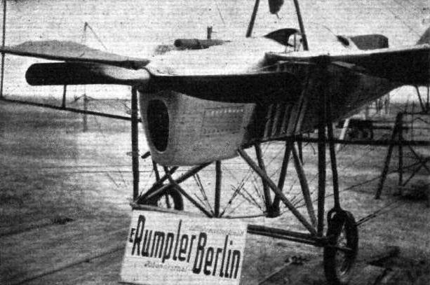
A Rumpler Taube with a 100 h.p. inverted Mercedes engine.
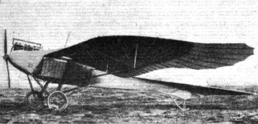
29. The Rumpler Taube.
16. The Rumpler Taube.
Linnekogel and a cinematograph operator on the Rumpler Taube.

29. The Rumpler Taube.
16. The Rumpler Taube.
Flight, September 18, 1914.
AIRCRAFT "MADE IN GERMANY"
WHICH MAY BE EMPLOYED AGAINST THE ALLIES.
30. The New Rumpler Taube
is of an improved type, chiefly as regards the wing bracing, which in this machine is effected by means of stranded cables instead of the girder structure under the wings. The bracing cables are taken to pyramidal cabanes or pylons above and below the fuselage, and instead of the flexing wing tips usually found on monoplanes of the Taube type, upturned ailerons are fitted. These, it should be noted, are hinged along an axis forming an angle with the transverse axis of the main planes. The only feature constituting this machine one of the Taube class is its Zanonia-form wings, it otherwise following standard practice as regards its fuselage, tail planes and chassis. The flexing elevator has been replaced by one of the hinged, divided type, whilst the rudder is hinged to the stern post, and not half above and half below the fuselage. The chassis is built up of four steel tubes forming two pairs of Vs, in the angle of which rests the axle, which is sprung by rubber shock-absorbers. Evidently the reduction of head resistance effected by substituting cable bracing for the girder structure under the wings has considerably increased the speed, for with a 100 h.p. Mercedes engine this machine is capable of doing about 74 m.p.h.
Flight, October 16, 1914.
AIRCRAFT "MADE IN GERMANY"
WHICH MAY BE EMPLOYED AGAINST THE ALLIES.
17. The Rumpler Flying Boat
does not differ materially in its general arrangement from the various well-known American flying boats. The hull or boat has a single step placed approximately under the centre of gravity. The bottom of the boat behind the step has a concave curvature, gradually flattening out towards the stern. In front the boat is flat bottomed. Constructionally it is built up over a framework of ash covered with three-ply and six-ply wood on the sides and bottom respectively. The two seats, which are situated just in front of the leading edge of the lower main plane, are placed side by side, the pilot sitting on the right. Control is by means of rotatable hand-wheel, mounted on a vertical pivotted column, and a footpath for the rudder. The engine, a 150 h.p. 6-cylinder Benz, is mounted on a structure of steel tubes approximately half way between the two planes. It drives directly a propeller placed behind the main planes, of which the upper one has the trailing edge cut away in the centre to provide the necessary clearance. In front of the engine, and mounted on the engine bearers, is the radiator, whilst the petrol and oil tanks, which have a capacity sufficient for a flight of four and a half hours' duration, are placed down in the hull, whence the fuel is forced up to a small service tank near the engine by a pressure pump.
The upper main plane, which has a considerable overhang, the weight of which is taken by struts sloping outwards from the bases of the outer inter-plane struts, is built up in five sections in order to facilitate transport. The outer sections or extensions are hinged, and may be folded down, thus reducing the overall span of the machine to that of the lower plane. The inter-plane struts are of streamline section, and built up of two pieces of spruce hollowed out and glued and bound together.
The tail planes are built up of frameworks of steel tubing covered with fabric. They consist of a fixed horizontal tail plane, to which is hinged the divided elevator, and of a triangular vertical fin, to the trailing edge of which is hinged the balanced rudder. Two small wing-tip floats, supported on steel tube structures, provide the necessary lateral stability on the water.
17. The Rumpler Flying Boat.
Flight, July 3, 1914.
FOREIGN AIRCRAFT NEWS.
New World's Duration Record.
BRIEF reference was made in our last issue to the splendid flight of Basser on a Rumpler biplane on the 24th ult., when he made a non-stop of 18 hrs. 11 mins. He started at 3.49 p.m. on the 23rd ult. and landed at 10 a.m. the next morning. Landsmann on an Albatros biplane who started at Johannisthal at 9.9 p.m. on the 33rd ult., after circling above the aerodrome for some time was driven away by a storm and eventually landed at Liegnitz in Silesia at 2.25 the following afternoon, having made a non-stop flight of 17 hrs. 17 mins. The previous duration record was Poulet's 16 hrs. 28 mins. made in April last on a Caudron.
Splendid as was Basser's record, it was beaten within four days by his rival Landsmann who, starting at 8.30 p.m. on Saturday last flew over a course between Johannisthal and Schulzendorf for 21 hours 49 mins. without stopping, the flight only coming to an end through the petrol supply failing. Altogether 625 litres of fuel and 50 kilogs. of oil were used while the distance covered was about 1,000 kiloms. Landsmann used an Albatros biplane which, like Basser's Rumpler, was fitted with a 100 h.p. Mercedes engine.
Flight, September 18, 1914.
AIRCRAFT "MADE IN GERMANY"
WHICH MAY BE EMPLOYED AGAINST THE ALLIES.
31. The Rumpler Biplane
is one of the newest types of German biplanes, as it made its first appearance on the last day of the "Triangle" race. The rectangular section fuselage is of very roomy proportions as in all Rumpler machines. It is covered in front with aluminium, and a slight turtle-back is formed by three-ply wood; the rest of the fuselage is covered with fabric. The chassis is similar to that of the new monoplane, so that spare parts may be employed to replace any broken parts of either monoplane or biplane.
The wings have been designed with a view to facilitate erecting and dismantling, and differ from usual practice in that the upper plane does not join in the centre as in nearly all other German biplanes, but follows more the English practice of having a short centre section attached to the fuselage by four tubes, which remains in place when the wings are dismantled. Ailerons are fitted to the upper plane only, and the control cables do not, as in previous Rumpler machines, pass through the interior of the plane, but under the lower plane and up through openings to the top plane. The interplane struts are streamline steel tubes, which are quickly detachable, and the cross-bracing is by means of stranded steel cables. Pilot and passenger are installed tandem-fashion in separate cockpits, the passenger sitting in front. The engine fitted as standard is a 100 h.p. Mercedes.
Flight, June 5, 1914.
THE PRINCE HENRY CIRCUIT, 1914.
MACHINES IN PRINCE HENRY CIRCUIT.
The Schwade Biplane is the only machine of the pusher type with a rotary motor entered in the competition. It is somewhat reminiscent of the Henry Farman biplane, having a very pronounced overhang of the top plane. The engine is an 80 h.p. Stahlhertz rotary motor mounted in the rear end of the nacelle.
Flight, September 18, 1914.
AIRCRAFT "MADE IN GERMANY"
WHICH MAY BE EMPLOYED AGAINST THE ALLIES.
32. The Schwade Biplane
is of the "pusher" type, and is to all intents and purposes a copy of the Henry Farman biplane. It differs from that well-known machine in minor details only, and does not, therefore, need a lengthy description here. The engine fitted is an 80 h.p. Stahlhertz rotary motor, mounted in the rear of the nacelle. The chassis is similar to that of the large span H. Farman biplane flown by Carr in the Aerial Derby this year, and consists of four Us of steel tubes, the lower portion of which is joined in pairs to form short skids. The main planes are, like those of the H. Farman, characterised by a very pronounced overhang to the top plane, the weight of which, when the machine is on the ground, is taken by wires passing over king-posts on top of the upper plane. The weight fully loaded is 1,532 lbs., and the loading a little over 3 lbs. per sq. ft. The speed is 60 m.p.h. with an 80 h.p. Stahlhertz engine.
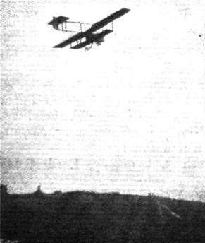
32. The Schwade biplane.
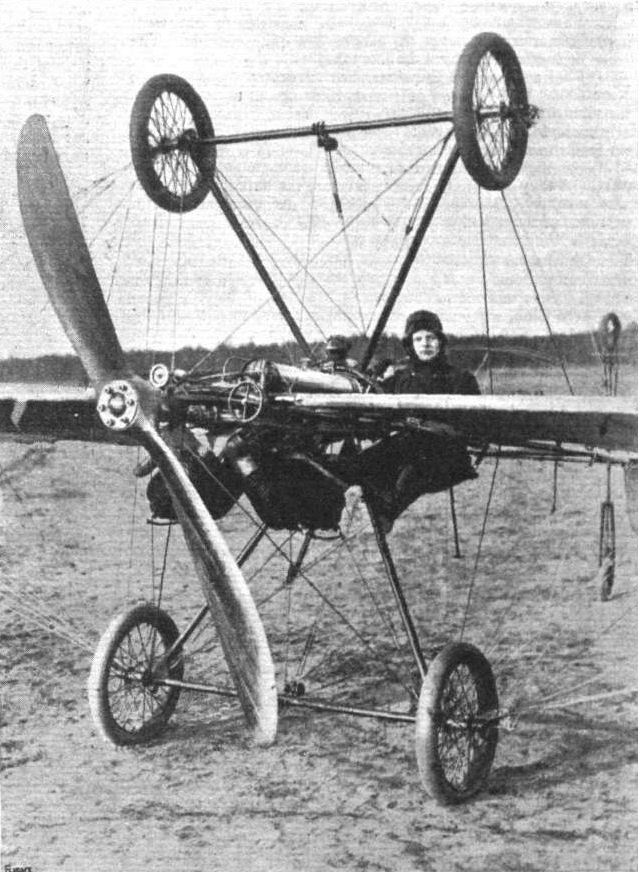
THE LATEST IDEA FOR LOOPING THE LOOP. - Pilot Gustav Tweer has been making trial flights on the above machine, constructed so that he can land upside down if necessary, having, as is seen, chassis and wheels both above and below the plaaes. He has been flying this machine at Bork.
Flight, September 18, 1914.
AIRCRAFT "MADE IN GERMANY"
WHICH MAY BE EMPLOYED AGAINST THE ALLIES.
34. The Union Arrow Biplane
has its main planes sloping backwards at a very pronounced angle. Its fuselage, which is of rectangular section, is very deep and narrow, and tapers to a vertical knife-edge at the rear, where are carried the tail planes, which consist of a fixed stabilising plane mounted on top of the fuselage, a divided elevator, and a vertical fixed fin, to the trailing edge of which is hinged the rudder. The chassis is of a very simple type, and consists of two pairs of steel tubes, each pair of which forms a "V" as seen from the side. The tubular axle rests in the angle between the chassis struts, from which it is sprung by means of rubber shock-absorbers. In addition to the slope backwards and the dihedral angle, the main planes are heavily staggered forward.
Flight, November 6, 1914.
AEROPLANE TYPES.
THE GABARDINI MONOPLANE.
ONE of the most successful machines which have been produced in Italy is the Gabardini monoplane, many of which have been turned out from the works at Cameri, Novara. Although a first glance at the accompanying sketch plan and elevation gives one the impression that this machine is on Nieuport lines, it really differs from this latter make considerably, notably in the construction of the fuselage. The latter is constructed of steel tube reinforced with wood, forming a strong and light combination. The forward portion is rectangular in section from the nose carrying the engine - an 80 h.p. Gnome - to the rear of the pilot's and passenger's cockpit, where the lower longerons meet. From this point the remainder of the fuselage is of triangular section. This arrangement gives an excellent streamline form, and also allows plenty of room for engine, fuel tanks, control gear, and pilot and passenger. The triangular portion of the fuselage can be detached, thus greatly facilitating transport and housing.
The wings, which have a maximum camber of 190 mm., are built up on two main spars of tubular steel, upon which the ribs are loosely mounted so that they possess a certain amount of free movement when warping takes place. The ribs consist of single one-piece webs with top and bottom flanges. Holes are drilled in the webs of each rib for nearly the whole length, rendering the wing very light and strong. The empannage is somewhat unusual in that it is mounted well in advance of the vertical rudder, so that the latter has a wide range of movement. It consists of a fixed semicircular plane, with two similarly shaped elevator flaps hinged to the trailing edge. The fixed plane, elevators, and rudder are constructed of steel tubing. Lateral control is by wing warping operated by a central lever, which also controls the elevators. The rudder is actuated by pedals. The chassis consists of two skids, upturned in front to protect the propeller, connected to the fuselage by three struts each. A tubular axle carrying a pair of running wheels is mounted on the skids by means of elastic bands. A hydro, model is also made, which differs from the land machine in dimensions and in the attachment of the two floats. The principal dimensions of the land model are as follows :- Span, 9 m.; supporting area, 18 sq. m.; overall length, 7 m.; weight, empty, 350 kgs.; useful load, 350 kgs.; speed, 65-135 k.p.h.
Flight, May 2, 1914.
AVIATION IN NEW ZEALAND.
<...>
In the meantime, Mr. A. W. Schaef, who, as our readers will remember, has built a monoplane, fitted with a 35 h.p. Y Anzani, which was illustrated in these pages some months ago, has made one or two short flights at Lyall Bay and at Newton Park, Wellington, New Zealand. On March 16th, three flights of about 100 yards each at a height of 20 ft. were made over the beach at Lyall Bay, but unfortunately in landing on the last one a part of the chassis gave way with the result that the wings and propeller were damaged. Mr. Schaef, who, it will be recalled, is the representative of General Aviation Contractors, Ltd., in New Zealand, immediately set to work to get the machine repaired, and hopes that it will not be long now before he is able to make some really long flights.
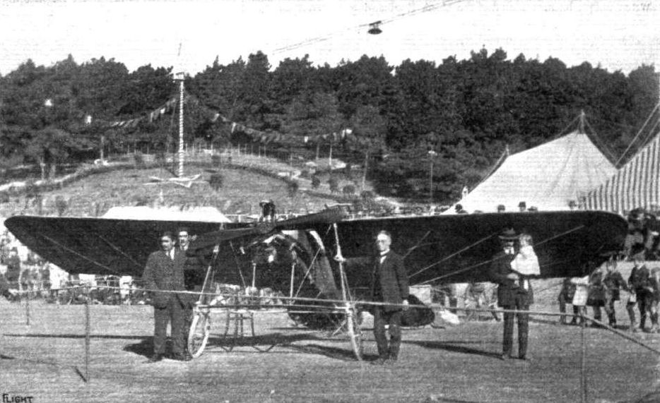
Mr. A. W. Schaef's 35 h.p. Y Anzani monoplane (built by himself.) at Newton Park (New Zealand) Aviation Meeting on March 24th. This machine, it will be remembered by our readers, was shown in flight in these pages some months ago.
AVIATION IN NEW ZEALAND. - A. W. Schaef on his Anzani-engined Amphibian monoplane (No. 2), which he constructed entirely himself. The photograph shows preliminary tests at Lyall Bay, Wellington, N. Z., in March last year, when it flew about 20 ft. above water for a short stretch.
AVIATION IN NEW ZEALAND. - A. W. Schaef's workshop at Wellington, N.Z., where he built his monoplane, .No. 1, in 1909, without any knowledge or experience other than that he obtained from the pages of FLIGHT. Our photograph shows the fuselage and landing chassis in its early stage, also the self-made propeller.
Flight, January 3, 1914.
FOREIGN AVIATION NEWS.
A New Sikorsky Biplane.
A NEW giant biplane, to take fifteen passengers, has now been built by Sikorsky, and during its first trials it carried four, six, and eventually ten passengers, together with petrol and oil, totalling to 384 kilogs. The machine has a span of 37 metres, it is 20 metres in length, while the lifting surface is 182 sq. metres, and the weight, empty, 3,500 kilogs. The fuselage resembles in general appearance that of the Nieuport monoplane. On each side of the fuselage are arranged two 100 h.p. Argus motors. As during these first tests the ground was covered with snow, the wheels were removed and the skids relied upon for landing.
Flight, March 7, 1914.
FOREIGN AVIATION NEWS.
More Passenger Records by Sikorsky.
IT is announced from St. Petersburg that on the 26th ult., Sikorsky, on his latest "Grand" biplane, carried sixteen persons, the weight lifted being 1,200 kilogs., for a period of 18 mins. He had previously flown with eight and with fourteen passengers. The next day, with eight passengers, he flew from St. Petersburg, by Gatchina, to Tsarkoie-Selo and back, the flight taking 2 hrs. 6 mins.
FOREIGN AVIATION NEWS.
A New Sikorsky Biplane.
A NEW giant biplane, to take fifteen passengers, has now been built by Sikorsky, and during its first trials it carried four, six, and eventually ten passengers, together with petrol and oil, totalling to 384 kilogs. The machine has a span of 37 metres, it is 20 metres in length, while the lifting surface is 182 sq. metres, and the weight, empty, 3,500 kilogs. The fuselage resembles in general appearance that of the Nieuport monoplane. On each side of the fuselage are arranged two 100 h.p. Argus motors. As during these first tests the ground was covered with snow, the wheels were removed and the skids relied upon for landing.
Flight, March 7, 1914.
FOREIGN AVIATION NEWS.
More Passenger Records by Sikorsky.
IT is announced from St. Petersburg that on the 26th ult., Sikorsky, on his latest "Grand" biplane, carried sixteen persons, the weight lifted being 1,200 kilogs., for a period of 18 mins. He had previously flown with eight and with fourteen passengers. The next day, with eight passengers, he flew from St. Petersburg, by Gatchina, to Tsarkoie-Selo and back, the flight taking 2 hrs. 6 mins.
Igor Sikorsky and his fifteen passengers, whom he took up in his giant aeroplane, "Ilia Mourametz," on February 25th, at Korpusny aerodrome, St. Petersburg, rising to a height of 300 metres and remaining up for 18 mins. 10 secs., a world's record. In the background is seen the cabin portion of this great air 'bus.
Flight, November 6, 1914.
AEROPLANE TYPES.
THE BEACHEY LOOPING BIPLANE.
ONE of the foremost exponents of looping the loop in the "States" is Lincoln Beachey, one of America's most daring stunt flyers. His first looping demonstrations were accomplished on a specially built Curtiss biplane of 24 feet span, after which he used a small tractor biplane built for him by the Glenn L. Martin Co. He then collaborated with Mr. Warren Eaton, and produced the machine under notice, on which he has put up many successful looping demonstrations. The prominent feature of the Beachey biplane is its small size combined with high power, the main planes having a span of only 21 feet, whilst the engine fitted is an 80 h.p. Gnome monosoupape. In general appearance it resembles the Curtiss "headless" biplane, though it differs considerably in detail. The main planes are built up in three panel sections, one in the centre 3 feet in span, and two outer ones of 9 feet. Each plane is built up on two main spars, the front one of D-section forming the leading edge being 1 5/8 ins. by 1 1/4 ins., and the rear one close to the trailing edge measuring 1 1/2 ins. by 1 1/4 ins. The spruce ribs and front and rear spars are laminated the former horizontally, and the latter vertically. The wing section has a maximum camber of 1 7/8| ins. about 1 ft 6 ins. from the leading edge. Six pairs of struts separate the top and bottom planes, and the outer sections are easily and quickly dismantled and assembled. Pivoted to the two rear outer struts of the main planes are the ailerons for maintaining lateral control. They are interconnected so that when one goes up the other goes down, and each has an area of about 13 sq. ft. The engine is centrally mounted midway between the top and bottom planes, and drives direct a 7 ft. 9 ins. diameter propeller situated at the rear of the main planes. The tail consists of a fixed stabilizing plane carried by two pairs of V outriggers, with two elevator flaps hinged to the trailing edge; a partially balanced vertical rudder is mounted between the elevators. The landing chassis is absolutely rigid, the necessary resiliency being obtained from the 4-inch tyres of the three 20-inch wheels. The principal dimensions of this machine are:- Span 21 ft. (over ailerons 25 ft.); length 18 ft. 4 ins.; chord 3 ft. 6 ins.; gap, 3 ft. 9 ins.; supporting area 147 sq. ft.; weight in flying order 773 lbs. ; speed 84 m.p.h.: climbing speed 1,125 ft. per min.
"VEE JAY."
Flight, February 28, 1914.
SOME AMERICAN FLYING BOATS.
The Benoist Flying Boat.
The Benoist flying boat represents an entirely different practice in flying boat design from that employed in the Curtiss and Burgess types. The respect in which the difference is mostly manifest is one of weight disposition, for whilst the two types mentioned above have the engine placed up between the main planes in order to raise the centre of gravity, the Benoist has the engine situated well down in the hull of the boat.
This, of course, gives this machine a comparatively low centre of gravity, and while this may, or may not, be a disadvantage in flight, it certainly renders the craft very stable on the water, and in modern machines, such as the Morane-Saulnier "Parasol," we have seen that a low e.g. is not prohibitive for good flying qualities.
The boat itself, which has a length of 23 ft., is built up of double spruce planking over a skeleton of spruce longitudinals and ribs. In the nose of the boat the bottom is swept upwards in order to assist the boat in getting into its skimming position in the shortest possible time. A single step, 5 ins. high, occurs at a distance of 9 ft. 8 ins. from the nose of the boat, and from the step to the stern the hull slopes upwards as well as tapering to a vertical knife's edge carrying the rudder. The deck is swept downwards very abruptly from the occupants' seats to a point behind the rear plane struts, in order to provide sufficient clearance for the propeller. In front of the seats is a cowl, formed by a structure of spruce stringers covered with canvas, the purpose of which is to protect the occupants from wind and water spray.
The method of mounting the engine is very interesting, as it serves at the same time to very materially strengthen the boat. Two strong spruce beams running parallel to each other practically the whole length of the boat serve as a support for the engine, and are spaced a distance apart sufficient to take the crank case arm bolts. The length of these beams is 17 ft., and in front of the step and under the engine they have a depth of 16 ins., and a thickness of two ins. From the step backwards they taper gradually to conform to the shape of the hull, and have been carefully proportioned for the various loads. Wherever possible, they have been lightened by hollowing them out. The engine drives through a chain transmission a single propeller situated behind the rear plane struts. The sprockets on the engine-shaft and propeller-shaft are of the same size, so that the gearing is 1 to 1. A tubular steel chain guard is fitted, and incorporated with it is a tubular radius rod which takes the pull of the chain, and provides easy adjustment of its length. This radius rod floats on ball-bearings at both ends. The tubular steel propeller-shaft is mounted between the main planes some 18 ins. below the trailing edge of the upper plane. Both ends of this shaft are carried on large combined radial and thrust bearings, which in turn are mounted on cast bronze retainers strongly supported to the central members of the cellule. Spruce struts tunning diagonally down to the leading edge of the lower plane, where that member joins the longerons of the boat, take the thrust reaction and preserve the rigidity of the rear bearing mounting. The propeller-shaft extension is fitted with a transverse pin, so that the engine can be started by the insertion of a starting handle. This operation is easily performed from either of the occupants' seats. The main planes, which are rectangular, as seen in plan, are both of equal span, and are built up in sections to facilitate transport. To the trailing edges of the outer sections of both planes are hinged ailerons of 8 ft. length, and a width of 1 ft. 8 ins. Mounted some distance above the deck of the boat is a fixed stabilising plane, to the trailing edges of which are hinged the two elevator flaps. The rudder is hinged to a post forming an extension of the stern post of the boat. A small portion of the rudder projects below the bottom of the boat, and serves as a water rudder when the machine is taxying on the water. The control levers are situated in front of the left hand seat (the seats are arranged side by side), and consist of a universally mounted lever operating the ailerons and the elevator.
Another lever actuates the rudder by a to-and-fro movement. The fuel tanks are placed in the hull on one side of the engine, and have a capacity for at least four hours' flight. All control cables are in duplicate, and are carried inside the hull, from which they emerge through a brass ferrule in the crown of the after deck. The general dimensions of the Benoist flying boat are :-
Span ... 35 ft.
Chord ... 5 ft.
Gap ... 6 ft.
Length ... 26 ft.
Length of hull 23 ft.
Weight, empty 1,190 lbs
Speed, fully loaded 64 m.p.h
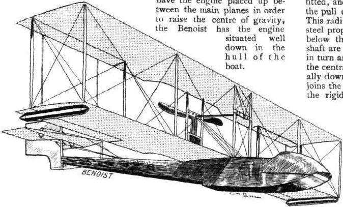
The Benoist flying boat.
Flight, October 16, 1914.
THE BOLAND AIRCRAFT AND JIB CONTROL.
As far back as 1907 - when the question of the Wright patents for aeroplane control was not such an important matter in America as it is to-day - the late Frank E. Boland started experimenting with his system of control. In 1908 he made some successful public flights on a canard-type biplane embodying his system of control. The latter was not only entirely original in form, but possessed undoubted properties as regards automatic stability. With this system of control wing-warping ailerons and vertical rudders of the orthodox type are dispensed with, and in their place are two "jibs" mounted one at each extremity of the main planes. These jibs serve to control conjointly both the lateral balance of the machine and its direction in a horizontal plane, the direction up and down being governed in the usual way by means of an elevator. In this way the control has been brought down to the simplest form possible - almost as simple as that of a motor car - for only two movements are necessary, the rotating of a wheel for steering to right or left, and a fore and aft movement of the vertical column carrying the wheel for longitudinal control. The jibs, which are somewhat pear-shaped, are mounted at the extremities of the main planes as shown in Fig. 1. They are pivoted about an oblique axis extending from the lower end of the front strut to a point about one-third from the top of the rear strut at an angle of 45° to the horizontal. The axis passes through the jib from the lower foremost corner close to the leading or forward edge, so that there is considerably more surface below and at the rear of the axis than there is above and forward of the same. Normally each jib is in a vertical plane, forming a side curtain at each end of the planes - (a), Fig. 1 - but on the rear edge of either of the jibs being pulled inwards - (b) and (c) Fig. 1 - the jib so moved presents a surface - in the direction of flight - inclining upwards both fore and aft, and outwards. This is equivalent to a surface having a negative angle of incidence, and produces a downward pressure, as well as a drag, on that side of the aeroplane at which the jib is pulled in. To make a turn, therefore, the jib on the side it is desired to turn is pulled in, with the result that a drag is caused on that side as well as a depression causing the machine to bank over the correct amount in turning. When the turn is complete the other jib is pulled in for an instant and the machine strightens out. Side-slipping on a turn is, it is claimed, impossible, as the jibs are so arranged and proportioned that they automatically provide the correct amount of bank at all times. To a large extent lateral balance is maintained by the jibs when in their normal position - as in the early Voisin machines with side curtains - but should the machine bank over owing to being caught by a side gust, &c, the jib on the high side is pulled in immediately the bank is felt, when the machine will be brought to an even keel without deviating from a straight course; if this bank is not corrected, however, the machine will merely make a turn corresponding to the amount of bank. The jibs, which move inwards and one at a time only, are connected to a control wheel by cables attached to the former near the trailing edge, whilst a spring loaded cable is attached to the leading edge of each jib and to some convenient part of the machine for the purpose of bringing the jib back into the normal position after being released.
The Boland "Tailless" Biplane.
This system of control has been tried on several types of machines. The first was a canard-type biplane, but as the model turned out in 1913 differed only in detail improvements we will confine our remarks to the latter type, which is illustrated by Fig. 2. It will be seen that it follows somewhat the general arrangement of the English "Valkyrie" monoplanes. The main planes are double-surfaced and built up in three sections. The centre section includes the chassis, nacelle, and engine, and so forms the main unit to which the outer sections, each measuring 15 ft., are attached. The latter are built up on two main spars, the front one of which forms the leading edge, whilst the rear spar is spaced a distance of two-thirds the chord from the front one, so that there is a large amount of flexible trailing edge. The ribs are of the Wright type, consisting of top and bottom spruce battens, with solid spruce blocks in between. Top and bottom planes are separated by eight pairs of spruce struts, the balancing jibs being mounted on the two outer pairs. Mounted on the lower plane of the centre section is a coracle-like nacelle, the front portion, containing the pilot's and passenger's seats, extending well forward of the planes, whilst the rear portion carries the power plant, the propeller being situated midway between the top and bottom planes just behind the rear spars. Unlike the "Valkyrie" monoplane, there is no fixed stabilising plane in front, but a large pivoted elevator measuring 12 ft. span by 3 ft. 6 ins. chord, carried by four outriggers some 13 ft. forward of the main plains. In flight the elevator is held presenting a lifting angle, so that it supports a certain amount of load. It is double-surfaced, having a pronounced camber, and is connected by cables to a Derperdussin type rocking yoke, which also carries the wheel operating the jibs. The round-nosed extensions of the outriggers can be detached from the latter, and with them the elevator, whilst the outriggers themselves are detached in two units, each consisting of an upper and lower longeron. The latter form continuations of the chassis skids, being connected to the top ones by vertical struts. A steel axle carrying a pair of running wheels is mounted by means of rubber bands on the skids proper under the front, pilot's, seat. The engine, which is mounted in the rear of the nacelle, is a 60 h.p. 8-cyl. water-cooled Boland, weighing complete 240 lbs. The principal dimensions are as follows :- Span, 35 ft. 6 ins.; chord, 5 ft. 6 ins.; gap, 5 ft. 6 ins.; supporting area of main planes, 373 sq. ft.; overall length, 21 ft. 9 ins.; weight with fuel, 900 lbs.; speed 60 m.p.h. This machine has also been flown with success as a hydro-biplane, the wheels having been replaced by two long pontoon floats.
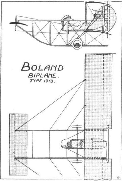
Fig. 2. - Plan and side elevation of the 1913 type Boland "Tailless" biplane.
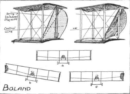
Fig. 1. - Details of the Boland Jib Control. Top: Two views of one of the jibs, on the left in normal position, and on the right pulled in. Bottom: (a) machine in normal flight; (6) correcting a bank; (c) starting a left-hand turn.
Flight, October 16, 1914.
THE BOLAND AIRCRAFT AND JIB CONTROL.
The New Boland Flying Boat
is the latest development of the Boland system, and is the first product of the Aeromarine Plane and Motor Co. of Avondale, N.J., formed recently to manufacture machines under the Boland patents. As will be seen from Fig. 4, this machine follows more conventional lines, and differs mainly in that no vertical rudder, ailerons or wing warping are employed. The boat has a single step situated at a point under the centre of gravity, and forward of the step the bottom is of V-form. The main framing consists of spruce longitudinals, 3/4 ins. square, with steam bent ash ribs 5/16 x 5/8 ins., spaced from 4 to 6 ins. The hull consists of an inner skin of cedar laid spirally about the tail, and from backbone to backbone forward of the step, covered with sheeting laid in marine glue. Over this is an outer covering of cedar laid fore and aft. Four transverse bulkheads, consisting of two and three skins laid diagonally with interlayers of canvas, provide five water-tight compartments and also serve to stiffen the hull. Auxiliary floats are mounted under the lower plane extremities. An arrangement of disappearing wheels for land use is also fitted, consisting of two wheels mounted forward of the centre of gravity on either side of the hull, with castor action and shock-absorbers similar to the Bleriot running gear. The wheels are raised out of the water into a stream-lined box, and lowered, from the pilot's seat, which is in the hull forward of the step and of the main planes. The latter are in three sections, an inner one 5 ft. 6 ins. span mounted on the boat, and two outer ones each 18 ft. 4 ins. span which are attached to the inner section. The control jibs, almost elliptical in shape, are pivoted at an angle of 45°, 22 ins. from the outer ends of the main planes. The planes are built up on two main spars of spruce, the front one forming the leading edge measuring i? ins. by 2 ins., and the rear one 1 in. by 3 ins. The ribs are of laminated spruce ribs with top and bottom flanges, and the struts are also of laminated spruce. The tail consists of a fixed stabilising plane with an elevator hinged to the trailing edge mounted high up over the stern of the boat, to which it is attached by means of a framework connected to flush hoops entirely encircling the boat, thus avoiding any openings through the skin of the latter. Immediately under the tail plane is a vertical fin - no rudder being attached, steering being accomplished by means of the jibs. Steering when on the water is by side plate rudders at the step. The engine, an 8-cyl. V, water-cooled Boland, is mounted high up in the centre plane section, and drives direct an 8 ft. propeller situated at the rear of the planes. The principal dimensions are as follows :- Span, 42 ft. 2 ins.; chord and gap, 5 ft. 6 ins.; supporting area, 435 sq. ft.; overall length, 26 ft. 6 ins.; weight with full load, 2,000 lbs.
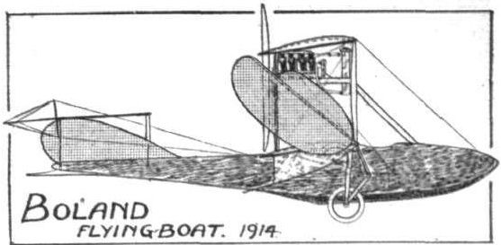
Fig. 4. - Side elevation of the new Boland biplane flying boat.
Flight, October 16, 1914.
THE BOLAND AIRCRAFT AND JIB CONTROL.
The Boland Monoplane Flying Boat (Fig. 3).
which made its first appearance at the New York Aero and Motor Boat Show in February this year, possesses several distinct features in design in addition to the jib control. It, also, is of the canard type, having a single pivoted elevator right forward. The boat is of quite unusual design, being very long and narrow, viz. :- 19 ft. 3 ins. and 2 ft. 10 ins. respectively. It is provided with two hydroplane steps spaced 6 ft. apart, and the bottom is flat except at the stern, which is concave. The hull, almost rectangular in section, is built up of mahogany ribs and stays covered with one-ply spruce and a layer of Irish linen doped with "Conover" and enamel varnish. Ash gunwales, 3 ins. deep, extend from stern to bows along the deck, and support at the forward extremities the elevator, which measures 9 ft. span by 3 ft. 6 ins. chord. The pilot's seat is situated in the hull amidships, and is protected by a scuttle dash; the passenger's seat is behind, immediately under the leading edge of the main planes and the horizontal centre of gravity. A small rudder is mounted under the stern to facilitate steering when taxying over the water.
The wings are in two sections, and are mounted some 3 ft. above the stern of the boat on either side of the engine bearers, which are supported on the gunwales by three pairs of struts. Each wing is built up on two main spars and double-surfaced, having a camber of 4 1/2 ins. tapering to 3 3/4 ins. and set at a dihedral angle of about 1 1/2°. The top wing bracing is by a central hollow mast of laminated oak and mahogany, fastened in the keel. This mast also carries sockets taking the roots of the front wing spars. Under bracing is by a girder understructure, extending from the boat outwards under the wings, the extremities carrying auxiliary floats and the balancing jibs. The latter are similar in shape to those on the previous machines, and function in exactly the same manner. The engine, a 70 h.p. Boland, is mounted between the wings behind the rear spars, and a portion of the trailing edge of the wings is cut away to receive the propeller, which is 6 ft. 8 ins. diameter. The radiator is mounted in front of the engine, and the fuel tank is underneath. The principal dimensions, are as follows :- Span, 28 ft. 8 ins.; chord, 6 ft. 10 ins.; supporting area (main planes), 181 sq. ft.; overall length, 20 ft. 8 ins.; weight (complete machine), 900 lbs.
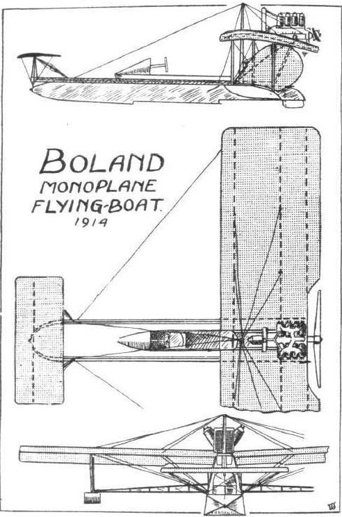
Fig. 3. - Plan, side and front elevation of the Boland monoplane flying boat.
Flight, February 28, 1914.
SOME AMERICAN FLYING BOATS.
The High-Powered Burgess Flying Boat.
Although in its general arrangement the Burgess flying boat is somewhat similar to the Curtiss, it differs very materially from it both constructionally and aerodynamically. One of the most characteristic features of this machine is the method employed for wing bracing. It will be seen from the accompanying sketch that only a single row of struts separate the main planes. It will be remembered that this method of construction is employed in the Breguet biplane, but whereas in the Breguet the necessary stiffness is provided by springs between the spars and the ribs, in the Burgess this is accomplished by cables running from the leading edge and rear spar of the upper plane to the main spar of the lower plane. This construction does not impress one as being particularly strong, especially in a machine with so powerful a motor as the 220 h.p. Anzani engine installed in this machine, but according to reports the makers do not seem to have experienced any trouble from this source. Each wing is built up on a tubular steel spar 3 1/2 ins. in diameter, a wood entering edge hollowed out for lightness, and a thin wood stringer parallel to the spar. The ribs are of wood, and are placed a foot apart. The upper plane is fitted with 5 ft. extensions, and has a span of 41 ft. 4 ins. The span of the lower plane is 33 it. 4 ins., and the gap between the planes is 7 ft.
The 20-cyl. Anzani engine is mounted between the planes, and drives directly a four-bladed propeller through an extension of the crank-shaft supported on ball-bearings on a steel tube structure built up from the hull. Petrol and oil are fed to the engine from two service tanks above the engine, and these are in turn replenished from larger tanks in the hull of the boat. The latter is somewhat similar to the one described in FLIGHT of June 28th, 1913, being of the plain non-stepped type. It is built up of mahogany planking over a framework of oak, and is divided by bulkheads into numerous watertight compartments. In order to facilitate shipment, the boat is built in two sections, which can be easily dismantled and erected. The tail planes are similar to those of the machine already referred to, and they, as well as the heel of the boat, are protected by a small tail skid or skeg mounted under the stern of the boat. The pilot's and passenger's seats are arranged tandem fashion, the pilot occupying the rear seat. As the lower plane has been left uncovered for a distance of about 6 ins. each side of the boat, the pilot has a very good view in a downward as well as all other directions. From the passenger's seat an even better view is obtained. The controls are of the Wright type, consisting of two levers, one of which controls the warp and rudder simultaneously, whilst the other operates the elevator. The general dimensions are :#
Length 30 ft. 6 ins. Gap 7 ft.
Span, upper plane 41 ft. 4 1/2 ins. Weight 2,050 lbs.
Span, lower plane 33 ft. 4 1/2 ins. Speed 75 m.p.h.
Chord 5 ft. 6 ins. Area 373 sq. ft.
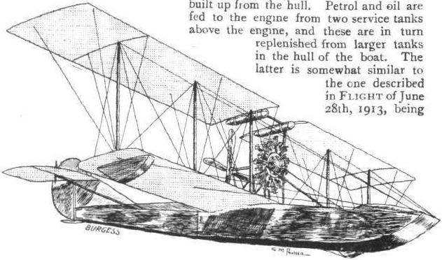
The Burgess flying boat,
Flight, June 19, 1914.
THE BURGESS-DUNNE HYDRO-BIPLANE.
DURING the last four months some very successful trials have been carried out in the United States with a Dunne hydro-biplane manufactured by the Burgess Company and Curtiss of Marblehead, Mass., U.S.A., who have acquired the sole rights to manufacture the Dunne machines in America. The production of a hydro-aeroplane on the Dunne principle presented numerous technical difficulties, in fact Lieut. J. W. Dunne himself considered that the inherent stability and the balance, both in the air and on the water, would be seriously affected by the fitting of afloat in place of the chassis, the former being considerably heavier and offering much more resistance than the latter. Mr. Burgess, however, set to work and went thoroughly into the matter of the Dunne principle, and after making exhaustive calculations as regards head resistance, weight, and centre of pressure under various conditions, he produced the first Dunne hydro-biplane, which balanced perfectly both on the water and in the air at the first time of asking. A comparison of the accompanying scale drawings of this machine with those of the land model published in FLIGHT for November 15th last, will show that except for the float, nacelle, and a few minor details, one does not differ from the other. In fact the principal dimensions and most of the constructional details are identical. It will, therefore, only be necessary for us to dwell briefly on the latter, so that we may confine our remarks to the modifications and actual performances. The swept-back planes are of the usual Dunne formation with the leading edge set at an inverted dihedral angle producing a negative angle of incidence at the tips, and are built up on two main spars of spruce, the front one forming the leading edge. The camber increases from practically nil at the centre to a maximum at the tips. It is to this peculiar formation that the Dunne machine owes its natural inherent stability, as has been described at length in the columns of FLIGHT.
At the centre of the lower plane is a short fuselage, rectangular in section and tapering fore and aft to a horizontal knife-edge. Mounted on the forward portion of this fuselage is a coracle-like nacelle, in which the pilot sits, whilst the rear portion carries the power plant. The latter consists of a 90-100 h.p. 8 cyl. Curtiss model O-X water-cooled engine driving direct an 8 ft. propeller. A single radiator is mounted immediately in front of the engine. The fuel and oil tanks, the former having a capacity of 22 gallons and the latter 4 gallons, are mounted on the upper longerons of the fuselage, two service tanks being placed within the latter just in front of the radiator.
The machine is supported on the water by a main central pontoon float 17 ft. 8 ins. in length and 3 ft. 1 in. beam, with a maximum depth of 15 ins. The float tapers to a horizontal knife-edge forward, and has a single hydroplane step at a point about one-third the length from the stern. It is divided into five transverse water-tight bulk-heads. Four pairs of spruce struts of steam-line section connect the float with the fuselage, the whole "chassis" being strongly cross-braced with wire. An auxiliary float is mounted at the bottom of each side curtain at the wing tips in order to support the latter when the machine rolls sideways. These auxiliary floats are similar in shape to the main float, but have no step. The Burgess Dunne is controlled in exactly the same manner as the land machine is. This control consists of ailerons only, operated by two separate levers, the right-hand lever operating those on the right side and vice versa. To ascend both levers are pulled back, causing the ailerons on each side to move up, and thus force the wing tips - which virtually form the tail of the machine, being located at the rear of the centre of gravity - down, a movement equivalent to that of the ordinary tail-elevator. To descend, the levers are pushed forward, with the reverse effect. When it is desired to direct the machine to starboard, the left-hand lever is pushed forward and the right-hand one pulled back, and the reverse for steering to port.
As regards the actual performances of this machine, Mr. Burgess made a few hops shortly after it was launched the latter part of February, but owing to exceptionally bad weather it was not until a few weeks later that the first successful flights were made at Salem Harbour, with Clifford L. Webster in the pilot's seat. Even then the weather was all but favourable, except as a severe test for the machine. However, the trials proved to be entirely successful, the machine rising easily from the water at a gentle angle. During one of his flights he locked the control levers and let the machine fly by itself. On May 2nd Webster put the second Burgess-Dunne through its tests before a number of members of the Aero Club of America. The second machine possesses several modifications calculated to increase its efficiency, otherwise it is similar to the other model. The radiator in front of the engine has been removed and a passenger's seat put in its place, whilst two radiators have been mounted on the rear float-struts. The demonstration with the second machine was made in a stiff N.W. wind with a choppy sea. After flying about two miles out to sea towards the observers with his hands off the controls, Webster made four circuits at 200 feet, taking his hands off the controls during the last circuit when the machine rose to a height of 500 feet. He then cut off the motor, and, with his hands still above his head, descended in a spiral to about 100 feet, when he resumed control and made another circular flight. Rising to a height of 500 feet, Webster once again took his hands off the controls, and glided in a straight line towards the observers. When 50 feet from the water, he resumed control, and, diving, alighted gently on the water and taxied to the observers' boat, to which the machine was moored for some time, withstanding the choppy sea exceptionally well. Another demonstration was made later on, in which Webster taxied some 200 yards away, and facing the observers he opened the throttle and raised his hands above his head. After hydroplaning for about 250 feet, the machine left the water and climbed gently to a height of 40 feet, when the pilot resumed control. Speed tests were also carried out, consisting of a run with and against the wind over a measured course of 1.2 miles. In one test the times taken were 59 secs, and 2 mins. 34 3/5 secs., whilst in another the times taken were 38 3/4 secs, and 2 mins. 38 4/5 secs. The average speed over a triangular course in a 10 m.p.h. wind was 5875 m.p.h. Numerous passenger flights were also made.
The principal dimensions of the Burgess-Dunne hydro-biplane are as follows :- Overall length, 24 ft. 8 ins.; span, 46 ft.; chord, 6 ft.; supporting area of main planes, 545 sq. ft.; weight of machine empty, 1,450 lbs.; useful load, 250 lbs.

General view of the Burgess-Dunne hydro-biplane floating on the water.
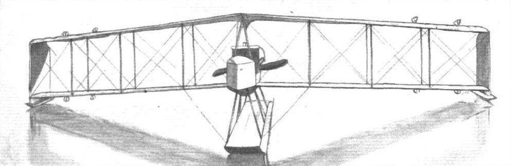
View from the front of the Burgess-Dunne hydro-biplane, showing how it is equally supported on the water by all three floats.
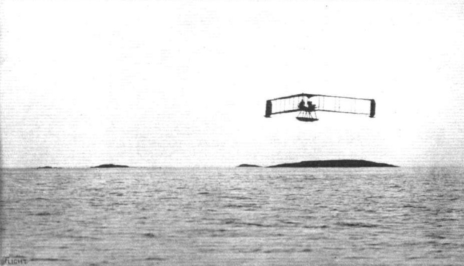
The Burgess-Dunne hydro-biplane in flight at Marblehead, piloted by Clifford L. Webster.

THE BURGESS-DUNNE HYDRO-BIPLANE. - Plan, side and front elevations to scale.
Flight, December 18, 1914.
EARLY AMERICAN STABILITY BIPLANES.
Two interesting examples of early attempts at stability aeroplanes hailing from America are the Steco and Carey biplanes, illustrated by the accompanying sketches, and incidentally it may be noted that it is claimed for both these machines that they circumvent the Wright aeroplane control patents.
<...>
Turning to the Carey biplane, shown in Fig. 2, it will be seen that the general design is not so complicated. Briefly, the Carey stability and control system - which was worked out by Edwin R. Carey in April, 1910 - consists of the employment of two surfaces, situated side by side which besides functioning as elevators also serve as balancing planes or ailerons. As a matter of fact, much the same system is to be found on the Dunne and 1909 type Cody machines, although Mr. Carey knew nothing of either of these at the time he designed his biplane. It is rather interesting to note the similarity between the Carey and 1909 Cody machines. For reversing the direction of flight of the former we have the front divided elevator and balancing planes with vertical surface in between, twin screws, and main planes much in the same relative positions as on the Cody machine. On the latter, however, there was a vertical rudder at the rear, and in later models ailerons were fitted to the planes in addition to the front elevators. Where the Carey system differs from that of the Dunne is that the ailerons on the planes of the latter are used as elevators as well as for steering to the right or left, whereas in the Carey machine the elevators are used as ailerons and steering is effected by means of a vertical rudder - although there is no reason why the latter should not be dispensed with. These elevators are operated by two separate levers as in the Dunne machine, and can be operated independently or simultaneously. The rudder is actuated by a foot bar. The elevator planes are carried by four pairs of outriggers, two for each plane, extending from the rear spars of the main planes. At the trailing edge of the latter are the two propellers driven by chains from the engine, which is mounted on, and in the centre of, the lower plane.
It is stated that a machine of this pattern was constructed and flown in 1911, but a new machine is to be built shortly, and it will be flown by a former Farman and Bleriot pilot. The principal dimensions of the machine illustrated are:-Span 28 ft.; chord 4 ft. 10 ins.; gap 5 ft.; supporting area 269 sq. ft.

The Carey stability biplane.
Flight, March 7, 1914.
SOME AMERICAN FLYING BOATS.
The Christofferson Flying Boat.
THE flying boat built by Silas Christofferson, and equipped with one of the new Hall Scott 100 h.p. engines, normally carries three passengers at a speed of 60 m.p.h., but it would probably carry another passenger if extra seating accommodation had been provided.
In its arrangement of the engine, placed down in the hull instead of between the planes, the Christofferson flying boat resembles the Benoist, and, like that craft, despite the low centre of gravity, flies very well. The boat itself, which measures 24 ft. 6 in. in length, is built up of 1/2 in. by 1/2 in. spruce ribs, reinforced by 1/2 in. longitudinal spruce stringers. The planking consists for the bottom of 1/4 in. cedar. The sides, up to a height of 14 in. from the bottom, are covered with cedar 3/14 in. thick whilst from this point to the gunwales the sides are covered with cedar 1/8 in. thick. The wind shield in front of the pilot's seat is covered with 1/8 in. mahogany. The single seat in front is occupied by the pilot, whilst the two passengers sit side by side in another seat on a level with the leading edge of the wings. Immediately behind the passengers' seats is the engine, which, through a 18-24 chain gearing, drives the propeller mounted 14 ins. below the rear spar of the upper main plane. The propeller-shaft is of hollow chrome nickel steel, and has a diameter of 2 ins. at the propeller, tapering to 1 1/2 ins. at the front. The radiator is placed behind the engine, while the petrol and oil tanks, which have a capacity of 20 gallons, are placed in the bottom of the hull under the engine.
It will be noticed that the upper main plane has a very pronounced overhang, the weight of which is taken, when the machine is at rest, by cables passing over king posts or cabanes situated above the outer pair of plane struts. In order to provide clearance for the propeller, the trailing edges of the planes have been cut away for a short distance from the hull. The ailerons fitted to the upper plane have a greater chord than the remainder of the trailing part of the wing, in order, no doubt, to render them more efficient. Constructionally, the wings consist of two main spars of I section formed by a web having three laminations, 3/4 in. thick, mortised into the flanges. The ribs are built up in the usual way of webs, bored out for lightness, mortised into the flanges, and glued and nailed.
The leading edge is composed of two strips, of which the front one is sharply pointed, whilst the trailing edge is formed by a strip of spruce with an oval leaving edge. Mounted on the upturned rear portion of the boat is the fixed tail plane, to the trailing edge of which is hinged the divided elevator. The rudder, which is partly balanced, is hinged to an extension of the stern post of the hull. The bottom of the boat, which is of the flat non-stepped type, is protected by two runners of spruce hollowed out for lightness and canvas-covered and waterproofed. Mounted under the tips of the lower plane are two floats cylindrical in front and flattened out at the rear.
The dimensions of the Christofferson flying boat, two of which it is stated have been ordered by the Norwegian explorer Amundsen, who intends to utilise them on his next expedition, are :-
Span of upper plane 49 ft. Gap 5 ft. 5 in.
,, lower plane 33 ft. 6 in. Weight 1,200 lbs.
Length over all 28 ft. Speed with 100 h.p. Hall Scott engine 60 m.p.h.
Chord 5 ft. 6 in.
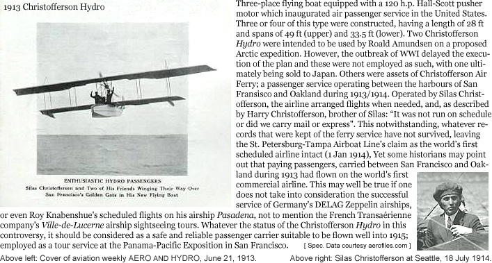
Christofferson Hydro 1913
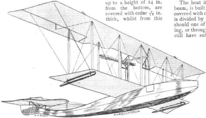
The Christofferson flying boat.
Flight, November 13, 1914.
AEROPLANE TYPES.
THE CHRISTOFFERSON TRACTOR BIPLANE.
ONE of the machines entered for the U.S. army trials is a 100 h.p. tractor biplane built by the Christofferson Aviation Co. of San Francisco, Cal., the constructors of the Christofferson flying boats. As will be seen from the accompanying sketch-plan and elevation, the design is more or less on German lines, although it possesses distinct features of its own. The planes are built up on two main spars, spaced well apart, somewhat after the fashion of monoplane practice, the rear spar being of small section. Spars and ribs are of spruce, and the wing section also follows monoplane design. The top plane is made up of three sections, being supported on the fuselage by two pairs of vertical tubular steel struts, and a pair of A struts, the latter situated between the rear pair. The outer sections are braced by cabanes, and hinged to the extremities of the rear spar are large-sized ailerons. The lower plane is in two sections, one on either side of and attached to the fuselage. Substantial stranded cable is employed throughout for the wing bracing. The fuselage is of rectangular section, very deep in front, and tapering to a vertical knife edge at the rear. The longitudinals are of spruce and ash, and the struts of the latter material, whilst the whole is cross-braced with stranded cable. Mounted in the nose is a 100 h.p. water-cooled Hall-Scott engine, which is entirely by a beaten aluminium hood, in which area of louvres in front and at the sides for the of admitting air to the radiator mounted the engine. This unusual position of the renders it most accessible, though it appears that the heated air passing from it into the passengers' cock-pit would not be very pleasant, except, perhaps, in cold weather. Underneath the radiator are the fuel and oil tanks, having a capacity for four hours' flight. Immediately behind the radiator, over the centre of gravity, is the passengers' cock-pit, accommodating two side by side, and behind this again is the pilot's cock-pit, situated well at the rear of the main planes, where an excellent view below and around can be obtained. The control consists of a Curtiss-type shoulder-yoke for operating the ailerons, and a rocking column carrying a hand wheel, the former for the elevator and the latter for the rudder. From the nose to the rear of the pilot's cock-pit the fuselage is wood covered, the remaining part being covered with fabric. The stabilising tail plane, to the trailing edge of which are hinged two elevator flaps, can be adjusted as to its angle of incidence. The chassis consists of two pairs of U struts, mounted to the fuselage immediately under the main planes, carrying an axle and pair of wheels, and a pair of V struts attached near the nose of the fuselage, carrying a single wheel. Another pair of struts connects the latter with the U struts. The axle carrying the two wheels is sprung by means of coil springs enclosed in cylindrical casings attached to the U struts. The principal dimensions are as follows:- Span, upper, 39 ft.; lower, 30 ft. 6 ins.; chord, 5 ft. 6 ins.; gap, s ft. 9 ins.; supporting area, 382 sq. ft. ; overall length, 32 ft.; weight, empty, 1,325 lbs.; speed, 35-75 m.p.h.; climbing speed, 4,000 ft. in 10 minutes.
"VEE JAY."

Flight, January 10, 1914.
A NEW AMERICAN STABILIZER.
FROM America comes some details of a new device for securing automatic stability that has just been tried and found to work satisfactorily. Briefly, it consists of a disc of fabric stretched over a light framework of wood, and mounted some distance above the main planes. The two transverse edges are turned upwards about 10 ins., thus presenting a slight side area to a cross-current of air. Mr. William S. Luckey, the Curtiss pilot, has just been testing the device for its inventor, Mr. H. C. Fiske, and found that it increased very materially the lateral stability of his Curtiss biplane. The action of the stabilizer is as follows: Suppose the aeroplane on which the device is mounted begins to side-slip to the left. The upturned left side of the stabilizer then offers a certain amount of side area to the current of air which is travelling across the path of the machine. As the point of application of this transverse air current is a considerable distance above the centre of gravity, the machine naturally tends to return to its normal position. It is not evident wherein this device differs in effect from the usual dihedral angle of the main planes, and we should be inclined to think that while it may possess the advantages of the dihedral angle it would also suffer from the same drawbacks.
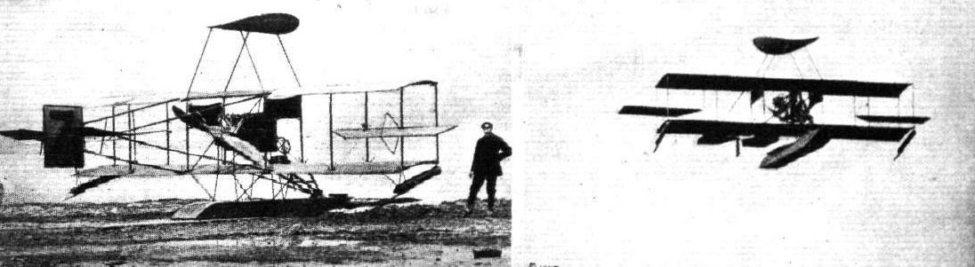
THE CURTISS HYDRO-AEROPLANE FITTED WITH DISC STABILIZER. - On the fight the machine in flight.
Flight, February 28, 1914.
SOME AMERICAN FLYING BOATS.
IN view of the announcement that an attempt is to be made during the coming summer to cross the Atlantic in a Curtiss flying boat, and bearing in mind the popularity this type of aircraft has attained in the United States, the following brief descriptions of some of the most successful American flying boats will enable our readers to form some idea of the stage to which this form of hydro-aeroplane has been developed. It is a fairly safe guess that for any attempts made under American auspices machines of the flying boat type will be employed, for in no other country have so many different constructors turned their attention to this particular type.
Since the Curtiss flying boat is the first to be entered, and as moreover its designer, Mr. Glenn Curtiss, is the pioneer of hydro-aeroplaning in America, it is only natural to begin this article with a description of one of the flying boats turned out by that most versatile constructor, more especially in view of the fact that the Curtiss machines are now being constructed in this country by Messrs. White and Thompson, Ltd., of Middleton, Bognor, Sussex. It is not easy to choose a model for description, for the dope has hardly had time to dry on the planes of one machine before a new and improved one is put through its trials. However, the flying boat built by the Curtiss Company for Mr. Harold F. McCormick, of Lake Forest, Ill., is fairly typical, as it embodies standard Curtiss features as well as several innovations which will be adopted in future machines. The boat, which is 23 ft. 7 ins. long, is built up of longitudinal members of ash I in. square, and placed 6 ins. apart, carrying the ribs, which are spaced 3 ins. apart. Over this framework is secured the planking, which for the sides of the boat consists of a thin spruce skin, whilst the bottom is covered with a planking of 5/16 in. thick mahogany and 3/4 in. spruce laid diagonally and having a sheet of very thick fabric, set in marine glue, between them. The whole outside of the hull is then covered with watertight canvas. Eight bulkheads divide the boat into watertight compartments, each of which is provided with an inspection door, which permits examination of the interior of the boat. Two of these compartments are claimed to possess sufficient buoyancy to keep the machine afloat should the remaining seven, for some reason or other, spring a leak. The bottom of the boat has a step of rather unusual shape. Instead of the usual box step, the step in this machine is of triangular form when viewed in plan, and has its apex pointed forward. Air is admitted to the step by two 1 1/2 in. copper tubes extending upwards through the hull. From the step the boat slopes upwards in order to facilitate getting off without the rear portion dragging. The body tapers to a vertical knife's edge at the rear, where are mounted the tail planes, consisting of fixed tail planes mounted a short distance above the hull and a divided elevator, hinged to the trailing edge of the fixed plane, a vertical fin and the rudder.
Just in front of the lower plane, and arranged side by side, are the pilot's and passenger's seats. In front of them are the dual controls, which consist of two rotatable hand wheels mounted on a single column, so that the machine can be controlled by either pilot or passenger at will. A to and fro movement of the wheel operates the elevator, whilst rotation of the hand wheel actuates the rudder.
The ailerons are operated by means of the shoulder yoke fitted as standard on all Curtiss machines, but any other control may be fitted. The deck of the boat in front of the occupants is swept upwards to form a wind shield. The gap between the main planes, of which the lower one is mounted on the upper longerons of the boat, is 5 ft. 6 ins., and the chord is 5 ft. 7 ins. Mounted on very strong bearings between the planes is the engine - a 100 h.p. 8 cyl. Curtiss - driving directly a propeller situated behind the main planes. A very stout oblique strut runs from the front part of the engine bearers to the upswept nose of the boat, and serves to transmit the strains due to momentum from the engine to the boat on alighting. On either side of the engine, and slung from the struts by means of steel straps, are the two tanks which contain the fuel, of which a supply sufficient for a six hours' flight can be carried. Outside the tanks, and immediately under the top plane are situated two blinkers, the object of which is to counteract, to a certain extent, the side area of the boat. The ailerons, which are of the usual Curtiss type, are pivoted approximately at their centre of pressure, so that little or no power is required to operate them, and they are inierconnected in such a manner that the drag on that of the lower wing is the same as that on the higher wing, so that there is no necessity to use the rudder in conjunction with the ailerons in order to maintain the direction of the boat. The general dimensions of the machine are :-
Span 42 ft, 2 ins.; Area 400 sq. ft.
Length 23 ft. 7 ins.; Weight 1,520 lbs.
Chord 5 ft. 7 ins.; Speed 53 m.p.h.
Gap 5 ft. 6 ins.
Flight, July 3, 1914.
TESTING THE SPERRY-CURTISS STABILIZER.
SOME very interesting demonstrations are reported to have been made with the Sperry stabilizer fitted on a Curtiss flying boat, in connection with the "Concours de la securite en aeroplane" on Friday week. The scene of the demonstrations was the Seine at Bezons, and the tests were carried out under the official observation of the judges of the competition. Piloted by Mr. Sperry, Jun., the son of the inventor of the gyroscopic stabilizer, the Curtiss flying boat left the water easily and rose to a height of about 400 ft. The mechanic was then seen to leave his seat and walk out along the lower plane, whilst the pilot held his hands above his head in order to show that the machine was controlled by the stabilizer only. This performance was repeated several times, and on another flight Mr. Sperry was accompanied by one of the judges - Commandant Barres - in order to make absolutely certain that the pilot did not use the controls.
The Sperry gyroscopic stabilizer consists of a quadruple gyroscope actuating the ailerons and elevator, and driven by the engine at the rate of 12,000 r.p.m. The longitudinal attitude of the machine is regulated by means of a small wind vane (which is seen in our photograph at the top left, attached to one of the engine struts) actuating one of the gyroscopes. If the speed of the machine drops below a certain limit, the vane depresses the elevator through the intermediary of the gyroscope. If, on the other hand, the speed is increased owing to a dive, the elevator is pulled up so as to "flatten out" the path of the machine. A clutch is provided by means of which the gyroscopes can be brought into or put out of action at the will of the pilot.

WATERPLANE RACING AT LAKE MICHIGAN. - A snap of a Curtiss flying boat, with two passengers on board, by the passenger in another Curtiss flying boat when racing neck and neck along Lake Michigan. Beyond is seen Lincoln Park (Chicago) Yacht Harbour.
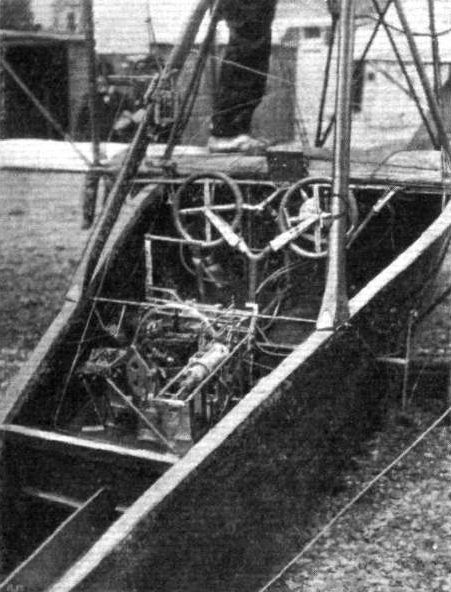
The gyroscopic installation on the Sperry-Curtiss machine.
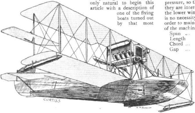
The Curtiss flying boat.
Flight, June 26, 1914.
THE TRANS-ATLANTIC FLIGHT.
LIEUTENANT PORTE'S NEW ROUTE.
THE Curtiss flying boat, "America," on which Lieutenant J. C. Porte, R.N., proposes to attempt the flight across the Atlantic, is now finished, and has been erected at Hammondsport, N.Y. Preliminary tests are being made over Lake Keuka, the first, in which the machine carried Lieut. Porte, Mr. Hallett, the mechanic, and Mr. Glenn Curtiss, being made on Tuesday and giving the results expected. If the tests justify anticipations, the machine will be dismantled and sent to St. John's, Newfoundland, to await favourable weather, and it is hoped to start on July 15th or 16th. The original plan, it will be remembered, was to take the direct route from Newfoundland to the Irish coast, but this has now been abandoned, and Lieut. Porte and his companion will set their course for the Azores, whence they will proceed to the coast of Spain. Arrived here they will follow the steamship route as far north as Ushant, a small island off the cost of Normandy, and from here it is intended to set the course for England.
By adopting this route, the greatest distance to be covered is approximately 1,200 miles between Newfoundland and the Azores, and Lieut. Porte feels confident that the two Curtiss engines will be able to stand up to a run of sufficient duration to complete this distance. In their tests on the bench, under conditions approximating as near as possible to those of actual flight, the two motors have completed 30-hour non-stop runs.
The principal difficulties which the trip presents are navigational ones, and to solve these Lieut. Porte has had the best expert assistance. It is understood that he may possibly have the advantage of the assistance of Capt. Creagh-Osborne, R.N., in the adjustment of his compasses and other navigational problems, as this officer, who is Superintendent of the Compass Department at the Admiralty, will be on leave of absence in Canada, and has accepted an invitation from Lieut. Porte to inspect the Curtiss flying-boat and witness the start at St. John's should his other engagements allow of it. It is hoped that the Washington Meteorological Office will render most valuable assistance in enabling the start to be made at the right moment, and all experts who have been consulted admit that Lieut. Porte, in choosing the route that he has selected, has adopted the course most likely to have the greatest number of factors in his favour.
A possible opportunity for a favourable start from Newfoundland would be afforded by a large high-pressure area south of latitude 40° N., and a constant succession of shallow cyclonic systems travelling eastwards north of that latitude, advantage being taken of the north-west wind in the rear of one of these, and the welt wind on the north side of the high-pressure system to start for the Azores, trusting to a south-west wind to assist on the eastern side of the Atlantic, due to the presence of a low-pressure system in that section. A start cannot be made with any prospect of success unless some such conditions prevail.
The machine to be used for the trip will not, as originally intended, be a tractor biplane with a single 200 h.p. Curtiss engine, but a large flying boat somewhat similar in its general arrangement to the standard type Curtiss. Pilot and passenger will be accommodated in a roomy cockpit entirely covered in and fitted with sliding windows for purposes of observation and ventilation. Behind the two seats, which are arranged side by side, will be the sleeping quarters furnished with a mattress on which the pilot and his passenger may in turn lie down to have a rest, and which will moreover serve as a floating "raft" in case of accidents.
The dual control will be slightly different from the standard Curtiss control, which, it will be recalled, consists of a rotatable handwheel for steering, a to-and-fro movement for the elevator, and a shoulder yoke for the ailerons. As the trans-Atlantic machine has very large ailerons, it has been thought inadvisable to employ the yoke, which imposes a considerable strain on the pilot's shoulders, and in its stead a pivoted foot-bar is fitted, by means of which the ailerons are operated. Rudder and elevator are controlled by means of a rotatable wheel on a rocking column.
The boat itself is more or less of the usual Curtiss type, but has been more carefully streamlined in order to reduce head resistance. In spite of its large size - it has an overall length of 32 ft. and a beam of 4 ft. - the hull is very light, weighing only about 550 lbs. It is built up of a framework of ash and spruce covered with a planking of cedar 1/4 inch thick, which is coated with oiled canvas. The wings, in addition to being much larger than those of the standard type Curtiss - the span of the upper plane is 72 ft. and that of the lower plane 46 ft., whilst the chord is 7 ft. - are of a different section, being of a curvature similar to the N.P.L. section, which is expected to considerably increase the efficiency.
Instead of the single 200 h.p. engine which it was originally the intention to use and which was actually constructed, two Curtiss engines of the type known as the O.X., each of 100 h.p., will be employed. Each engine will drive a single propeller of 8 ft. diameter. The total weight of the machine in flying trim is stated to be 5,000 lbs., divided up in the following manner: Fuel, 2,000 lbs., made up of 300 gallons of petrol, and 25 gallons of oil; hull, 550 lbs.; pilot and passenger, 300 lbs.; engines, wings, tanks, and supplies, 2,150 lbs.
In the accompanying map is shown the route which will be followed, and the various distances that have to be covered. It will be noticed that for a considerable portion of the first stage, from Newfoundland to the Azores, the route will intercept numerous steamship routes, so that on this part of the journey at any rate the ntervals between sighting ships should not be very long. It is hoped that captains of vessels will render assistance by flying the following signals to indicate on which side of the aviator's route they are :-
When on the north side of the route fly the following signals from the foremast:
If 90 miles to 60 miles from route, fly square flag, ball, square flag.
If 60 miles to 30 miles from route, fly square flag, square flag.
If 30 miles to o miles from route, fly square flag.
When on the south side of the route the same signals are to be flown, but from the mainmast.
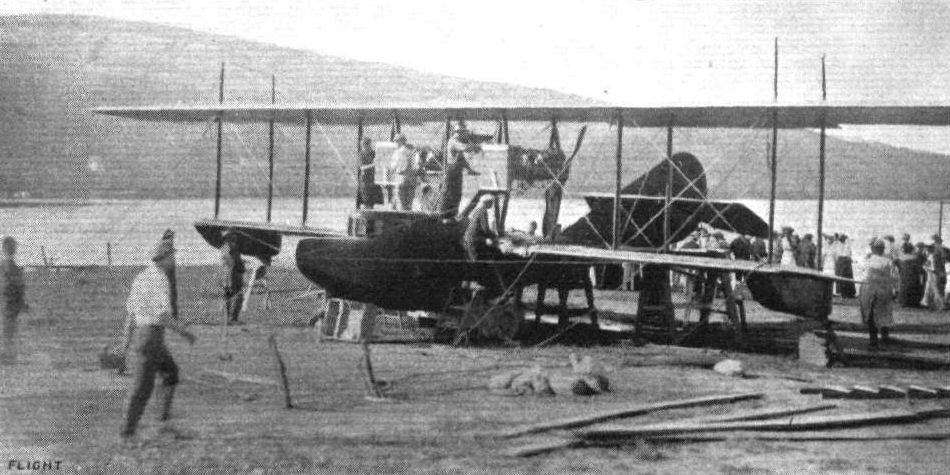
THE "AMERICA," THE CURTISS TRANS-ATLANTIC FLYING BOAT. - The following are the chief dimensions: Length over all, 34 ft.; length of hull, 30 ft.; width of hull, 4 ft.; depth of hull, 6 ft.; length of cabin, 7 ft.; height of cabin, 5 ft.; width of cabin. 4 ft; span of upper plane, 74 ft.; span of lower plane, 4 6 ft.; chord, 7 ft.; gap, 7 ft. 6 ins.; weight, empty, 3,000 lbs.; weight, fully loaded, 5,000 lbs.; speed, 62-65 m.p.h.

The Curtlss flying boat "America," at rest on the water.
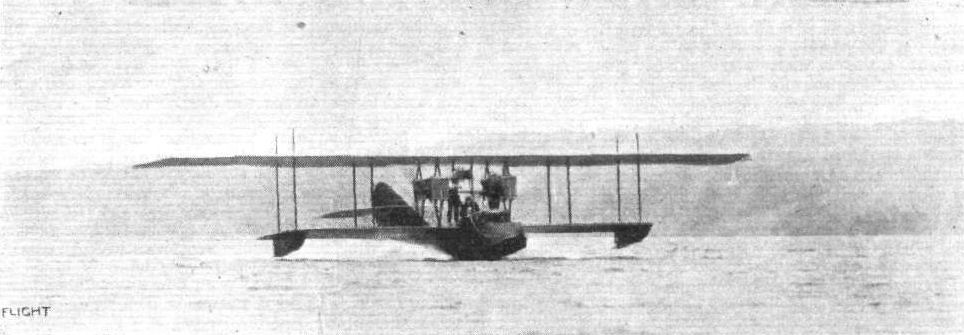
The "America" hydroplaning.
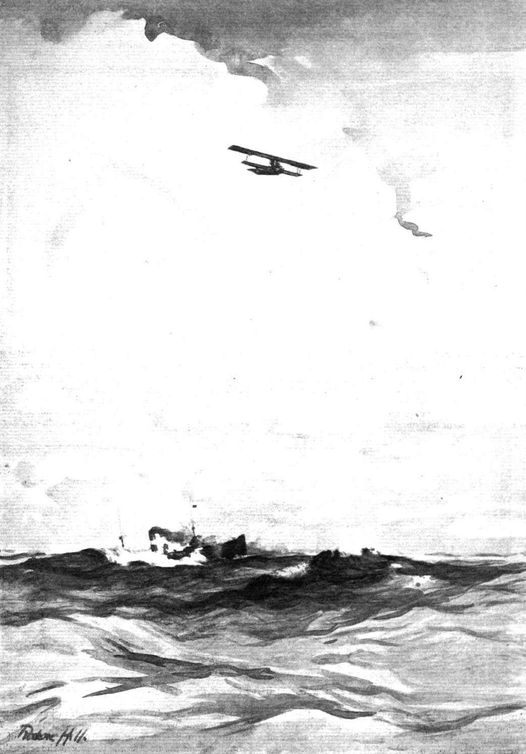
THE ATLANTIC FLIGHT AS IT MAY BE. - From an original drawing by Roderic Hill.
Flight, December 11, 1914.
AEROPLANE TYPES,
THE CURTISS TRACTOR BIPLANES.
FOR some time past the Curtiss Co. of Hammondsport, NA., have been experimenting with tractor biplanes - a type that has only just recently come into favour in the U.S.A. - and have as a result of their experience turned out some machines that compare very favourably with European practice. These have given very satisfactory results, and several have already been delivered to the U.S. Government. Two or three different types of these Curtiss "model J" tractors have been manufactured, but they only differ in dimensions and details. The model shown in the accompanying sketch-plan and elevation is a two-seater reconnaissance type with pilot and passenger seated in tandem. The planes are similar in construction to those employed on the Curtiss flying boats, but having a different wing section. They are of one-piece construction, with main spars of I section ash, hand-grooved and shaped. The ribs are built up of spruce, and all the important joints are copper bound, whilst the whole frame-work is strongly braced with piano wire internally and with stranded cable for the interplane bracing. The planes are covered with unbleached linen doped with Curtiss oil and water proof dope. Large ailerons, measuring 10 ft. by 2 ft, are hinged to the rear spars of the top plane, which has a greater span than the lower. Top and bottom planes are separated by two pairs of laminated spruce struts on either side of the fuselage, and in the centre by four struts forming extensions of the fuselage struts. The interplane struts are mounted in quick detachable fittings bolted to the spars. The planes are perfectly straight: that is, they have no dihedral angle, but the top plane is slightly staggered forward.
The fuselage is of rectangular section tapering to a vertical knife-edge at the rear, and with a turtle-back extending behind the pilot's seat. It is built up of ash longerons and nine sets of ash and spruce struts joined by steel clamps in such a manner that the longerons are not pierced. Cross bracing is by steel wire and Binet turn-buckles, which permit easy adjusting for the necessary rigidity. Mounted in the nose of the fuselage, on a laminated ash and spruce bed, is the 90 h.p. 8-cyl. V water-cooled Curtiss OX engine, immediately in front of which is the radiator. The whole of the engine is enclosed by a Duralumin bonnet, in the sides of which are louvres. The front of the engine bed is bolted to the fuselage nose plate, to which are anchored the longerons. At the rear the engine bed is supported by a hard wood cross member connected to the second vertical pair of fuselage struts, which are made extra strong for the purpose. Coupled direct to the engine is an 8ft. Curtiss tractor screw. Just behind the engine is the passenger's cockpit, and behind the latter, at the rear of the main planes, is the pilot's, both being protected by streamline cowels. Dual controls are provided, either of the Curtiss shoulder-yoke type or Deperdussin pattern. The maximum depth and width - at the cockpits - of the fuselage is 2 ft. 11 ins. and 2 ft. 2 ins. respectively.
The tail consists of a semi-circular stabilising plane, to the trailing edge of which are hinged two elevator flaps, mounted on the top longerons of the fuselage, and a partly balanced vertical rudder pivoted to the last strut of the fuselage. This strut is also extended below the latter in order to carry a sprung tail skid. The chassis consists of two skids 6 ft. long, attached to the lower longerons of the fuselage by three pairs of struts each. Sprung to the skids by means of rubber bands is a tubular steel axle carrying a pair of disc wheels. The principal dimensions of this machine are as follows :- Span, upper plane, 40 ft. 2 ins.; lower, 30 ft.; chord, 5 ft.; area of main planes, 346 sq. ft.; area of stabilising plane, 30 sq. ft.; area of elevator, 16 sq. ft.; area of rudder, 7 sq. ft.; overall length, 26 ft. 4 ins.; speed range, 45-75 m.p.h.; climbing speed, 400 ft. per min.
Another model made is a scout, which differs from the model just described in that the main planes have a span of 24 ft. top and bottom, and that ailerons, 7 ft. by 2 ft., are fitted to both top and bottom planes. The chassis is also somewhat modified. This model has a speed range of 45 to 80 m.p.h. and a climbing speed of 500 ft. per minute. Both these models can be converted into hydro-biplanes for over-water flying by the fitting of a single pontoon float to the chassis in place of the wheels, and as such have been very successful.
<...>
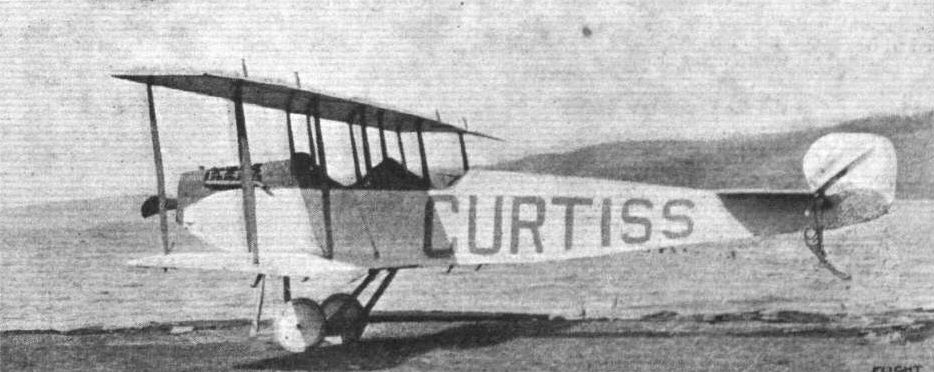
Fig. 2. - One of the Curtiss model J scouts.
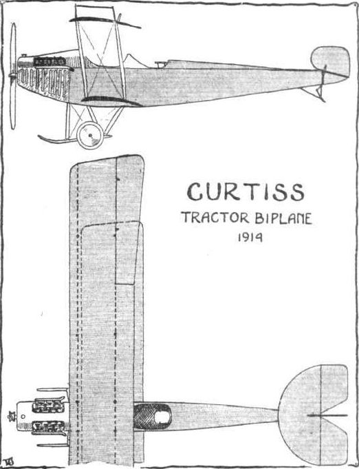
Fig. 1. - Sketch-plan and elevation of the Curtiss model J reconnaissance tractor biplane.
Flight, February 21, 1914.
THE CURTISS MONOPLANE FLYING BOAT.
AN extremely interesting machine has been turned out just recently at the Hammondsport factory, where the Curtiss machines are built. It has been specially built for Mr. Raymond V. Morris, of New Haven, Con., and differs very considerably from the other machines turned out by the Curtiss firm. In the first place, it is a monoplane; and secondly, the design and construction of the hull are new. Early in January its owner put it through some tests on Lake Keuka, New York, with very successful results. Perhaps the most interesting feature of this new Curtiss machine is to be found in the wings. These are of the form that is so popular in Germany, known as the "arrow plane," in which the wings are swept back so that in plan form they resemble an arrow-head. The wing section employed on this new machine is similar to that of the Bleriot XI bis and the B.E. 2, and the method of wing bracing is like that found on many of the "taube" machines in Germany. The wings are mounted some 4 ft. above the hull and are attached to a steel superstructure forming the engine bed, whilst the bracing consists of four pairs of "V" struts, two on each side of the hull, the apex of each pair joining a single transverse spar extending under the wings from each side of the hull. In construction the wings follow usual practice, being built up of two main spars with ribs spaced at intervals of about one foot. The leading edge of the plane curves rearwards at the tips to a point where it meets the ailerons. The latter are almost triangular in shape, and are counter-balanced, that is, when one goes up the other goes down. The tail consists of a triangular plane with two elevator flaps hinged to the trailing edge mounted above the stern of the boat, together with a vertical fin, triangular in shape, and a rudder. The engine, as previously mentioned, is mounted in the centre and on the top of the plane, the propeller being situated immediately at the rear of the trailing edge of the latter. The type of engine fitted is one of the latest 90 h.p. 8-cyl. Curtiss OX models water cooled, with the radiator mounted in front on the leading edge of the plane. In addition to two pairs of tubular steel struts supporting the engine bed, a pair of stout wood struts extend forward from the engine to the hull to a point just in front of the pilot's cockpit, and serve to take the thrust of the propeller. In shape the hull is very like a torpedo, except that the stern tapers to a vertical knife-edge, and that the bottom from bow to about midships, where there is a step, is of the double concave type employed on the latest navy pattern Curtiss boats. The framework of the hull is built up of ash longitudinals and ribs. On the framework is a diagonal layer of 3/32 in. mahogany planking, and over this is a covering of heavy "Sea Island" cotton set in marine glue. Another layer of mahogany planking of the same thickness, but laid longitudinally, forms the outer covering. Immediately under the plane is the pilot's cockpit, the seat being placed low down in the hull in order to afford ample protection for the pilot from wind and spray. A second hole has been cut in the top of the hull, just behind the pilot, for a passenger, but when the pilot only is on board this hole is covered up. An auxiliary float is attached to each outer extremity of the transverse bracing spar. The control is of the usual Curtiss pattern, shoulder yokes for the ailerons, rocking column for the elevator, and foot-bar for the rudder. The principal dimensions of this new air-boat are as follows :- Overall span from tip to tip of ailerons, 34 ft.; span of wings, 28 ft.; maximum chord, 5 ft.; wings swept back 7; Supporting surface, 120 sq. ft.; length of hull, 22 ft.; maximum beam, 2 ft. 6 ins.; maximum depth, 3 ft.; weight with pilot and fuel, 1,200 lbs.
In view of the success of the new craft it is anticipated that the new model will prove to be very popular during the coming season. It will be remembered that Messrs. White and Thompson, Ltd., of Middleton, Bognor, are the representatives of the Curtiss firm in Great Britain.

The Curtiss monoplane flying boat.
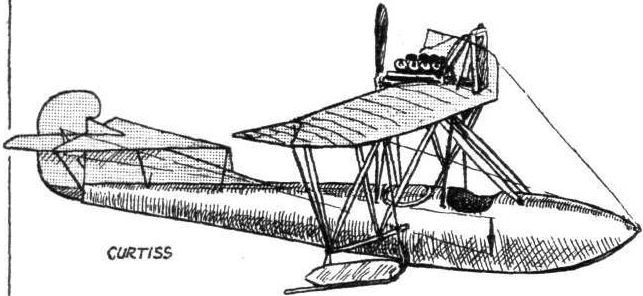
The Curtiss monoplane flying boat.
Front view of boat.
THE CURTISS MONOPLANE FLYING BOAT. - Plan, side and front elevations to scale.
Flight, December 11, 1914.
AEROPLANE TYPES,
THE CURTISS TRACTOR BIPLANES.
<...>
The latest Curtiss tractor (Fig. 3), built for the abandoned U.S. Military Trials, shown in one of the accompanying illustrations which we reproduce from our American contemporary Flying, differs from the model J tractors in the main planes and chassis. The former, which have a Morane-Saulnier plan form - larger span at the trailing edge - are set at a pronounced dihedral angle, and top and bottom planes are of equal span. The ailerons, of which there are two, are of substantial size, and are mounted between the top and bottom planes on the two outer rear struts.
The chassis consists of two skids, upturned at their forward ends, which project beyond the tractor screw, connected to the fuselage by three struts each. Two of the latter are connected to the skids close together, one on either side of an axle carrying a pair of running wheels and sprung to the skids. In other respects this machine is very much the same as those previously mentioned.

Fig. 3. - The latest Curtiss tractor biplane, built for the U.S. Army Trials.
Flight, June 12, 1914.
TESTING THE LANGLEY "AERODROME."
As briefly announced in our issue of June 5th, the well-known American aeroplane constructor and aviator, Glenn H. Curtiss, succeeded, on May 28th last, in making a flight on the tandem monoplane built by Dr. S. P. Langley in 1903. Contrary to a common report, this was the original Langley machine, and not a copy, as, although originally refused by the Smithsonian Institution, they subsequently agreed to let the original structure be used. Some of the ribs, which had been broken, were replaced and the wings resurfaced, but the original engine and propellers were used, as well as all of the framework and most of the original cross-wiring. During the first test, the object of which was to determine if the balance of the machine had been adversely affected by the added weight and head resistance of the floats and other fittings, Mr. Curtiss was taxying along the surface of the water at a moderate speed when the machine quietly lifted into the air and sailed steadily along for some distance.
This performance is all the more remarkable in view of the fact that the machine lifted not only the load which Dr. Langley had designed it to carry, but in addition lifted an extra weight of 340 lbs., in the form of floats and other fittings attached to the machine in order to facilitate launching it from the water. In previous trials, eleven years ago, the "Aerodrome," as Dr. Langley called his machine, was launched from a catapult on top of a house-boat, and wrecked through the failure of this launching apparatus.
Among those who witnessed the tests were Dr. Charles D. Walcott, Secretary of the Smithsonian Institution, and Dr. A. F. Zahm, Recorder of the Langley Aerodynamical Laboratory, and a number of well-known aviators. In a statement for the press, Dr. Walcott said: "I was well pleased with the launching this morning. Although the machine and pilot weighed 340 pounds more than the machine and pilot of 1903, it rose gracefully from the water on the very first trial, and maintained remarkable stability both in the air and on the water. I assigned to Mr. Curtiss the task of rehabilitating the original machine and of testing it over the water, first, for the purpose of vindicating Dr. Langley's design, and, secondly, to ascertain the practical value of his design in the present state of aviation. It is my hope that succeeding trials will amply justify the good opinion which aeronautical engineers, both here and in Europe, have long entertained of Dr. Langley's design."
Below we publish the abbreviated history of Dr. Langley's study and experiments as communicated to us by Mr. Glenn H. Curtiss :-
"The story of Samuel Pierpont Langley's study and experiments in connection with aeronautics begins in 1887, some years before serious-minded people considered aerial navigation with machines heavier than the air practical, and extends over nearly sixteen years. During that time Mr. Langley established and successfully demonstrated many principles which have since proved invaluable to the science of aviation.
"Mr. Langley's main object was to establish by experiment the possibility of, and the conditions necessary for, transporting a body heavier than the air through that medium. He began with studies of toy aeroplanes propelled with rubber bands, which led to more elaborate experiments with planes, propellers, steam and gas engines, and other accessories, and to his final experiments with a man-carrying machine propelled by a gasoline engine which, although built eleven years ago, is nearly as efficient as those evolved by the engineers of today. In his early experiments he met with many discouragements, but his persistency led finally to those results which entitled him to be called 'The First Bird Man.'
"The results of his experiments were printed in popular form in several magazines and periodicals, while his technical scientific reports were issued by the Smithsonian Institution during his term as Secretary from 1887 to 1906. His first real contribution to the science of aeronautics was entitled 'Experiments in Aerodynamics,' published in 1891, which covered his early physical researches in relation to aerodynamics, and showed that the real problems of aviation were those of guiding and elevating a plane rather than of supporting it. Mr. Langley had already established the possibility of the latter by means of his suspended planes, the plane dropper, and other apparatus.
"The second aeronautical treatise of Mr. Langley was on the 'Internal Work of the Wind' published in 1893, in which he pointed out the various internal forces of the atmosphere upon which objects might rely for support apart from their own power.
"In 1911, a complete and detailed account of his investigations relative to the models and the large machine was issued under the title of the 'Langley Memoir on Mechanical Flight.'
"Having secured a grasp upon the fundamental principles of air resistances, and matters pertaining to aviation generally, Mr. Langley undertook the construction of the first heavier-than-air model machine in 1892. He felt that it would be impossible to conduct further investigations regarding flight without studying flight itself. The first model aeroplane, or 'aerodrome' as he termed it, was completed after four years of experimentation. It was a steam-driven machine, with two sets of monoplane wings arranged in tandem, and a tiny steam plant which weighed only 7 lbs. complete and yet developed 1 1/4 h.p. Many boilers, burners, and frames were built and discarded before the aerodrome was finished, and then the problem of launching it confronted him. This was finally accomplished by means of an overhead track from which the machine, when ready to fly, was shot into the air by a series of springs.
"The first successful flight was made on May 6th, 1896, at Quantico, on the Potomac River, by this tandem type plane, which had a wing spread of 13 ft. and a total weight of 30 lbs. The flight occupied 1 min. 20 secs., during which time the little machine covered a distance of 3,000 ft. It was immediately started again, and made a flight of over 2,300 ft. These were the first flights of a machine heavier than air and propelled by its own power ever made in the history of the world. Subsequent nights of this machine and others with both steam and gasoline power proved their efficiency, and also demonstrated the correctness of Mr. Langley's theory of the practicability of flight.
"Early in 1898, the Government became interested in the possibility of employing large flying machines in time of war, and the President, through the Board of Ordnance and Fortification of the War Department, requested Mr. Langley to build a man-carrying machine. This the inventor undertook, and finally in 1903 he had completed the construction of the full-sized steel machine, despite many handicaps and delays encountered in securing a suitable engine and other accessories.
"The large engine is a gasoline one, built in the Smithsonian shops under the direction of Mr. Charles M. Manly. It is a five-cylinder engine, developing a little over 52 actual horse-power, and weighing, with radiators, batteries, and 20 lbs. of cooling water, only 207 lbs., a little less than 4 lbs. per horse-power. The complete aerodrome ready for flight weighed about S50 lbs., including the aviator, and had a total supporting area of 1,040 sq. ft., or a total of 1.25 sq. ft. of surface to the pound.
"Before the completion and test of the large machine, however, a quarter-size gasoline model was constructed, and flown with success on August 8th, 1903.
"Two attempted flights with the man-carrying machine were made on October 7th and December 8th, 1003, but owing to an inefficient launching apparatus the aerodrome was not successfully launched into the air, but fell into the water before it got free from the track and launching ways. It was immediately taken out of the water, carefully cleaned, and has since been stored in the Smithsonian Laboratory.
"The War Department did not make an additional allotment for further experiments, and Mr. Langley, owing to lack of funds, never undertook to fly the machine again. During recent years, progress in aviation has brought much to the attention of the world regarding flying machines which Mr. Langley not only knew but could have demonstrated had further support been accorded."
Flight, July 17, 1914.
THE LANGLEY MACHINE TESTS.
BEING in the United States on a visit to the Wright Bros., Mr. Griffith Brewer made a special trip to Hammondsport to get at first hand details regarding the trials which were recently made by Mr. Glenn Curtiss with the Langley machine. According to Mr. Brewer's enquiries opinion seems to be very divided as to whether the machine did actually rise so that all the floats were completely clear of the water. Mr. Brewer, in sending the photo, of the machine in flight, which he says is the best secured from a boat by the local photographer, writes :-
" - the tail float is in the water, and it is doubtful if the front floats are really off. I also enclose two photos, taken by myself, one showing the old restored machine standing out in the open, where it is daily exposed to thunderstorms except for a cloth over its middle, and the other showing one of the Curtiss mechanics sewing extra pieces of wood stick on to the tail ends of the ribs, in order to improve the curvature ready for the next trials to be made when the weather is again absolutely calm."
Apropos of his visit to Hammondsport Mr. Griffith Brewer addressed, under date June 21, to the New York Times the following letter upon the subject of the Langley machine, which will doubtless be of interest to many of our readers :-
"In view of the statements that have been appearing in the American newspapers since I arrived over here ten days or so ago, I should like to give a few facts for the benefit of aviation in America:
"1. The Langley machine did not fail to fly in 1903 for want of power. It had 52 horse-power to drive it, and weighed about 750 pounds, whereas the Wrights had only 12 horse-power, and their machine weighed 741 pounds. Langley, therefore, had four times the power that the Wrights had, yet he failed where they succeeded. The reasons Langley did not succeed were as follows:
"2. The machine was inefficient. Langley was under the mistaken impression that it was necessary to have extreme lightness and large surface in order to fly. The result was that he designed wings of very small strength, which were extremely inefficient in lift, and also which possessed unnecessary resistance.
"3. The propellers designed by Langley were very inefficient. The propellers made by Langley gave an efficiency considerably less than 40 per cent., compared with the 66 per cent, efficiency given by the propellers constructed by the Wrights, and used on their first machine in 1903. The original Wright propellers have since been copied on the best machines to-day, and form the standard from which modern propellers are designed. More than 80 per cent, of the propellers in use on modern machines to-day are less efficient than the propellers designed and used by Wilbur and Orville Wright on their first machine.
"4. Langley had no practical means of balancing an aeroplane in the air during flight. Langley employed wings fixed at a dihedral angle to each other in order to maintain balance, and this method had been suggested by others many years before. Many experimenters have tried this system of balance and failed because the first side gust of wind will upset the machine and cause it to dive to the ground. The Wrights did not use the dihedral angle for maintaining balance, but they invented and used means for altering the angle of the ends of the wings, and this method or an equivalent is employed to-day on all machines which fly in the air.
"5. Langley had no practical means of launching his machine. The first attempt to launch it resulted in a portion of the machine catching in the launching apparatus, and the second attempt resulted in another portion catching, with the same result of plunging the machine into the water below. The Wrights succeeded in producing a practical launching apparatus which launched their machine successfully the very first attempt, and which repeated this successful launching thousands of times afterward.
"6. Even if Langley's machine had been successfully launched, and had been able to sustain itself in the air with its inefficient surfaces, and had been able to maintain the necessary flying speed by means of its inefficient propellers, it could only have been flown in the calmest of air, because the first gust would have upset it. The Wright machine, on its very first flight, was flown in a 27-mile-an-hour wind, which would have upset any machine ever thought of then or since which was not fitted with the adjustable wing control invented by the Wrights.
"Langley is very rightly credited with having made a number of scientific experiments with miniature wings and surfaces, in order to ascertain data of 'lift and drift.' This is greatly to his credit, but it should not be forgotten that the Wrights also made independent experiments and obtained a number of readings from which they compiled scientific tables and drew diagrams of pressure curves far more complete and accurate than any previously made, either by Langley or by any other scientist. Unfortunately, the Wrights have been unable to publish these data hitherto, owing to the tardy protection afforded by the patent laws, which necessitate the guarding of exclusive knowledge, to supplement the incomplete patent protection of new inventions.
"Why, in view of all these facts, are the American newspapers making such a fuss of what Langley might have done had his machine been built differently and had he known more facts on the subject of flying?
"Why has Langley's most interesting machine been taken out of the Smithsonian Institution and altered from its original historic state to try to make it fly?
"Why, if such a demonstration were considered desirable, was not the old historic relic left untouched and a copy made to satisfy an insane curiosity?
"Why, if such a demonstration were decided on, was not some impartial, unprejudiced person chosen to make the tests instead of the person who has been found guilty of infringement of the Wright patent?
"Why, if the Langley flying machine was a practical flying machine, did not those in charge of the machine try to make it fly without alteration? With the knowledge gained during the past ten years this should have been easy if the machine as invented by Prof. Langley was really capable of flight.
"Why were Langley's old propellers taken off and propellers of more modern shape substituted?
"Why, if the tests have been successful, are there no photos available of the old machine in flight?
"All these things are incomprehensible to me, especially as I have just arrived from England, where the Aeronautical Society of Great Britain has only last month been paying its annual tribute to the memory of its honored member, the late Wilbur Wright, whom it regards as the joint inventor with his brother Orville of the first actual flying machine.
"GRIFFITH BREWER."

Front wings and main floats of the Langley tandem monoplane.

Side view of Langley tandem monoplane.
The machine, minus its wings, in its open-air "garage," and on the right, one of the wings of the old Langley machine being strengthened at the Curtiss works at Hammondsport.
Rear view showing cruciform tail planes and large dihedral angle on main planes of Langley tandem monoplane.
The Langley machine over the surface of Lake Keuka.
Flight, December 11, 1914.
EDDIES.
Among the many pupils who benefited from Jas. V. Martin's tuition at Hendon, was Miss Lily Irvine, who, as will be recalled, became Mrs. Martin in the summer of 1911, and later went with her husband across the "pond." Mrs. Martin, or, to preserve her nom de vol, Miss Irvine, has still retained all her old enthusiasm for flying, and has to her score a considerable number of successful flights, which in July culminated in a splendid bit of air work - a flight with a passenger of 70 miles across Lake Erie from Cedar Point to Euclid Beach in 59 minutes.
Starting from Cedar Point at 2.10 p.m. on July 23rd, Miss Irvine, having climbed to a height of 1,200 ft., steered in a north-easterly direction so as to clear the point at Vermilion. Huron was passed at 2.18, so that the first 11 miles were covered in 8 minutes. The rest of the time-table panned out as follows :- Vermilion, 2.30; Lorain, 2.40; Dover .Bay, 2.52; Eagle Cliff, 2.53; arrival at Euclid Beach, 3.09. On landing, Miss Irvine received her reward in an enthusiastic and well-deserved welcome, for the flight was one which any aviator might well be proud to have to his credit. At the commencement of the flight a rich banker offered to follow her in his fast motor boat so as to be at hand in case of accident, but Miss Irvine was not to be "mothered " thusly, and settled the matter in the following characteristic words, "We'll go it alone or not at all!"
Miss Irvine is now flying her husband's machines, and we shall look forward to recording more of her doings in the future.
"AEOLUS."

Miss Irvine in her professional aviation costume at Avondale, New Jersey, where she is now flying Capt. J. V. Martin's machines.
Flight, June 19, 1914.
AEROPLANE TYPES.
THE KANTNER-MOISANT MONOPLANE.
AMERICA has not produced many monoplanes that could be called original in design, most of them being of the Bleriot type, but in fairness it must be said that they possess many interesting points in details and construction. Such is the case with the Kantner-Moisant monoplane, which was built by the Moisant Aviation Co. to the designs of Mr. Harold Kantner, who has piloted the machine himself with some considerable success. At first sight this machine resembles the Morane-Saulnier monoplane, but on closer inspection it will be seen that there are two or three distinct differences. In the first place, the main planes are almost rectangular in plan-form, the leading and trailing edges being of the same span; secondly, the landing chassis is of the Bleriot type. The tail is of the balanced elevator type. The fuselage is of rectangular section from the nose to a point level with the trailing edge of the main planes, from whence it tapers to a horizontal knife-edge at the tail; it also decreases slightly in width from this point. The fuselage is built up in the usual box-girder style, wire braced, and is divided in the middle for the purpose of facilitating transport. The pilot's cockpit is situated well forward, while observation below is improved by cutting away a portion of the main planes at the leading edge of the main planes, and also from the rear spar to the trailing edge. The 50 h.p. Gnome engine is mounted in front of the fuselage, and is protected by an aluminium cowl or shield which extends to the cockpit, protecting the pilot from both wind and oil. The main planes are built up on two large spars, and taper slightly from root to tip. The top cabane, a pyramid of four steel tubes, is mounted well forward, and the wing cables have specially designed attachments whereby the detachment of the planes is easily and quickly accomplished. The chassis, of the Bleriot type, slopes forward in order to bring the wheels well forward to prevent the machine from turning over on its nose. The principal dimensions of this monoplane are: Span, 30 ft.; length, 21 ft.; chord, 6 ft. (root) 5 ft. 9 ins. (tip); supporting area, 698 sq. ft.; speed, 70 m.p.h.
"VEE JAY."

Flight, January 31, 1914.
SOME EXPERIMENTS WITH DIFFERENT SYSTEMS OF LATERAL CONTROL.
Mr. W. E. SOMERVILLE, of Coal City, Illinois, U.S.A., sends us the following interesting account of some experiments with different systems of lateral control, which he has carried out during the years 1910, 1911, 1912 and 1913, in order to determine the best form of ailerons:-
"Machines Nos. 1, 2 and 3, as shown in the accompanying photographs, all had shutters, which were not interconnected, and which were operated by opening the shutters on the higher wing, thereby partly reducing the area and consequently the lift, whilst the added resistance caused a drag, which retarded the speed of the higher wing tip.
"System No. 1 was found to be inefficient when the machine was near the ground, and so was discarded in favour of No. 2. This was quite good, and the machine would right itself almost immediately, while this form of ailerons also proved to be quite good as a rudder, in fact while the experiments were being carried out the rudder was very seldom used. However, as the shutters were kept closed by means of a heavy spring the action of opening them against the pull of the spring entailed some rather hard work, so this system was discarded.
"System No. 3 was fairly good, but not so effective as No. 2. It was used, however, on the 1912 machines by the aviators E. Korn and E. S. Daugherty. On my 1913 biplane a new design (No. 4) was tried. This system is practically the same as the Farman, but operates exactly the opposite way.
In order to correct a bank the aileron on the higher side is raised, thus causing a downward pressure as well as a drag on the higher wing. This, of course, accelerates the speed of the lower wing, and consequently increases the lift so that the machine rights itself without the use of the rudder. Then another system was tried in which the ailerons were interconnected, as in the modern Farman and Curtiss machines, but with the exception that when in their normal position the ailerons presented a negative angle of incidence to the line of flight. The ailerons were so adjusted that when the controls were moved to their full limit the aileron on the lower wing was in line with the trailing edge, whilst that on the higher wing presented the necessary resistance and downward pressure to right the machine. I consider this system the best because it is easy to operate, and produces practically no resistance on the lower side. It also appears to add considerably to the general stability of the machine. My object in testing so many systems was to produce a design which would be effective, efficient and safe, without causing any drag on the lower wing, and one which would at the same time work independently of the rudder. Nos. 2 and 4 are particularly suitable, since either ailerons or rudder may be used for both purposes.
"Although my machine has been flown repeatedly by M. Daugherty without ailerons and with only the rudder to maintain lateral stability, it is my opinion that ailerons are necessary if only to make one feel secure. The upturned wing tips assist greatly in giving one this confidence, as it prevents that sideslip which has proved fatal to many an aviator. Not only that, but they practically maintain lateral stability. This may seem a very strong claim, but it is a fact which has been proved on numerous occasions.
"I engaged a supposed aviator to fly my machine (later he informed me that he had never been in an aeroplane before). However, the 80 h.p. H. Scott was started, and away he went, climbing at a terrible angle. It was evident from the start that he knew nothing whatever about flying. When he had reached an altitude of about 250 ft. he did a banked turn, climbing all the while, and in this critical position he stopped the engine! The machine of course lost all headway and began to drop vertically. Gradually the lower wing and the tail rose to a level, and the machine commenced to glide forward and landed heavily, smashing two wheels and the skids, but suffering no further damage. The 'pilot' escaped without a scratch, but was half dead from fright!
"The upturned wing tips have saved my life on more than one occasion, for in my early experiments my machine was underpowered and very unreliable. I unfortunately, one day in June, 1910, gave a private exhibition to my family and a few friends in order to demonstrate my ability as an aviator. Well, the flight terminated with half of the machine in some trees, and the other half, with myself, piled on the ground. The engine being in front I was not much hurt, but the same cannot be said about my feelings, seeing that my family and friends had witnessed the performance. This finished my ambition to become a great aviator, and later, when I have occasionally tried my machines I have always taken good care to do so when my friends were not in sight."
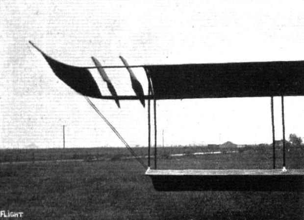
THE SOMERVILLE BIPLANE. - Type 1 Aileron fitted on 1910 experimental biplane, and also used in 1911.
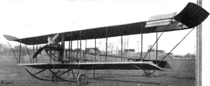
THE SOMERVILLE BIPLANE. - Type 2 Aileron used in 1910 experimental biplane.
Flight, January 31, 1914.
SOME EXPERIMENTS WITH DIFFERENT SYSTEMS OF LATERAL CONTROL.
Mr. W. E. SOMERVILLE, of Coal City, Illinois, U.S.A., sends us the following interesting account of some experiments with different systems of lateral control, which he has carried out during the years 1910, 1911, 1912 and 1913, in order to determine the best form of ailerons:-
"Machines Nos. 1, 2 and 3, as shown in the accompanying photographs, all had shutters, which were not interconnected, and which were operated by opening the shutters on the higher wing, thereby partly reducing the area and consequently the lift, whilst the added resistance caused a drag, which retarded the speed of the higher wing tip.
"System No. 1 was found to be inefficient when the machine was near the ground, and so was discarded in favour of No. 2. This was quite good, and the machine would right itself almost immediately, while this form of ailerons also proved to be quite good as a rudder, in fact while the experiments were being carried out the rudder was very seldom used. However, as the shutters were kept closed by means of a heavy spring the action of opening them against the pull of the spring entailed some rather hard work, so this system was discarded.
"System No. 3 was fairly good, but not so effective as No. 2. It was used, however, on the 1912 machines by the aviators E. Korn and E. S. Daugherty. On my 1913 biplane a new design (No. 4) was tried. This system is practically the same as the Farman, but operates exactly the opposite way.
In order to correct a bank the aileron on the higher side is raised, thus causing a downward pressure as well as a drag on the higher wing. This, of course, accelerates the speed of the lower wing, and consequently increases the lift so that the machine rights itself without the use of the rudder. Then another system was tried in which the ailerons were interconnected, as in the modern Farman and Curtiss machines, but with the exception that when in their normal position the ailerons presented a negative angle of incidence to the line of flight. The ailerons were so adjusted that when the controls were moved to their full limit the aileron on the lower wing was in line with the trailing edge, whilst that on the higher wing presented the necessary resistance and downward pressure to right the machine. I consider this system the best because it is easy to operate, and produces practically no resistance on the lower side. It also appears to add considerably to the general stability of the machine. My object in testing so many systems was to produce a design which would be effective, efficient and safe, without causing any drag on the lower wing, and one which would at the same time work independently of the rudder. Nos. 2 and 4 are particularly suitable, since either ailerons or rudder may be used for both purposes.
"Although my machine has been flown repeatedly by M. Daugherty without ailerons and with only the rudder to maintain lateral stability, it is my opinion that ailerons are necessary if only to make one feel secure. The upturned wing tips assist greatly in giving one this confidence, as it prevents that sideslip which has proved fatal to many an aviator. Not only that, but they practically maintain lateral stability. This may seem a very strong claim, but it is a fact which has been proved on numerous occasions.
"I engaged a supposed aviator to fly my machine (later he informed me that he had never been in an aeroplane before). However, the 80 h.p. H. Scott was started, and away he went, climbing at a terrible angle. It was evident from the start that he knew nothing whatever about flying. When he had reached an altitude of about 250 ft. he did a banked turn, climbing all the while, and in this critical position he stopped the engine! The machine of course lost all headway and began to drop vertically. Gradually the lower wing and the tail rose to a level, and the machine commenced to glide forward and landed heavily, smashing two wheels and the skids, but suffering no further damage. The 'pilot' escaped without a scratch, but was half dead from fright!
"The upturned wing tips have saved my life on more than one occasion, for in my early experiments my machine was underpowered and very unreliable. I unfortunately, one day in June, 1910, gave a private exhibition to my family and a few friends in order to demonstrate my ability as an aviator. Well, the flight terminated with half of the machine in some trees, and the other half, with myself, piled on the ground. The engine being in front I was not much hurt, but the same cannot be said about my feelings, seeing that my family and friends had witnessed the performance. This finished my ambition to become a great aviator, and later, when I have occasionally tried my machines I have always taken good care to do so when my friends were not in sight."
SOME EXPERIMENTS WITH DIFFERENT SYSTEMS OF LATERAL CONTROL.
Mr. W. E. SOMERVILLE, of Coal City, Illinois, U.S.A., sends us the following interesting account of some experiments with different systems of lateral control, which he has carried out during the years 1910, 1911, 1912 and 1913, in order to determine the best form of ailerons:-
"Machines Nos. 1, 2 and 3, as shown in the accompanying photographs, all had shutters, which were not interconnected, and which were operated by opening the shutters on the higher wing, thereby partly reducing the area and consequently the lift, whilst the added resistance caused a drag, which retarded the speed of the higher wing tip.
"System No. 1 was found to be inefficient when the machine was near the ground, and so was discarded in favour of No. 2. This was quite good, and the machine would right itself almost immediately, while this form of ailerons also proved to be quite good as a rudder, in fact while the experiments were being carried out the rudder was very seldom used. However, as the shutters were kept closed by means of a heavy spring the action of opening them against the pull of the spring entailed some rather hard work, so this system was discarded.
"System No. 3 was fairly good, but not so effective as No. 2. It was used, however, on the 1912 machines by the aviators E. Korn and E. S. Daugherty. On my 1913 biplane a new design (No. 4) was tried. This system is practically the same as the Farman, but operates exactly the opposite way.
In order to correct a bank the aileron on the higher side is raised, thus causing a downward pressure as well as a drag on the higher wing. This, of course, accelerates the speed of the lower wing, and consequently increases the lift so that the machine rights itself without the use of the rudder. Then another system was tried in which the ailerons were interconnected, as in the modern Farman and Curtiss machines, but with the exception that when in their normal position the ailerons presented a negative angle of incidence to the line of flight. The ailerons were so adjusted that when the controls were moved to their full limit the aileron on the lower wing was in line with the trailing edge, whilst that on the higher wing presented the necessary resistance and downward pressure to right the machine. I consider this system the best because it is easy to operate, and produces practically no resistance on the lower side. It also appears to add considerably to the general stability of the machine. My object in testing so many systems was to produce a design which would be effective, efficient and safe, without causing any drag on the lower wing, and one which would at the same time work independently of the rudder. Nos. 2 and 4 are particularly suitable, since either ailerons or rudder may be used for both purposes.
"Although my machine has been flown repeatedly by M. Daugherty without ailerons and with only the rudder to maintain lateral stability, it is my opinion that ailerons are necessary if only to make one feel secure. The upturned wing tips assist greatly in giving one this confidence, as it prevents that sideslip which has proved fatal to many an aviator. Not only that, but they practically maintain lateral stability. This may seem a very strong claim, but it is a fact which has been proved on numerous occasions.
"I engaged a supposed aviator to fly my machine (later he informed me that he had never been in an aeroplane before). However, the 80 h.p. H. Scott was started, and away he went, climbing at a terrible angle. It was evident from the start that he knew nothing whatever about flying. When he had reached an altitude of about 250 ft. he did a banked turn, climbing all the while, and in this critical position he stopped the engine! The machine of course lost all headway and began to drop vertically. Gradually the lower wing and the tail rose to a level, and the machine commenced to glide forward and landed heavily, smashing two wheels and the skids, but suffering no further damage. The 'pilot' escaped without a scratch, but was half dead from fright!
"The upturned wing tips have saved my life on more than one occasion, for in my early experiments my machine was underpowered and very unreliable. I unfortunately, one day in June, 1910, gave a private exhibition to my family and a few friends in order to demonstrate my ability as an aviator. Well, the flight terminated with half of the machine in some trees, and the other half, with myself, piled on the ground. The engine being in front I was not much hurt, but the same cannot be said about my feelings, seeing that my family and friends had witnessed the performance. This finished my ambition to become a great aviator, and later, when I have occasionally tried my machines I have always taken good care to do so when my friends were not in sight."
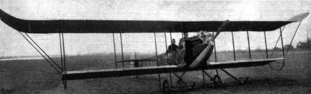
THE SOMERVILLE BIPLANE. - Type 3 Aileron used on 1912 biplane.
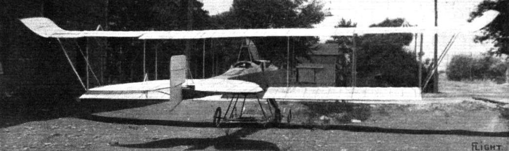
THE SOMERVILLE BIPLANE. - Type 4 Ailerons on 1913 machine.
Flight, December 18, 1914.
EARLY AMERICAN STABILITY BIPLANES.
Two interesting examples of early attempts at stability aeroplanes hailing from America are the Steco and Carey biplanes, illustrated by the accompanying sketches, and incidentally it may be noted that it is claimed for both these machines that they circumvent the Wright aeroplane control patents. The Steco biplane was designed during the latter part of 1910, a favourable verdict having been expressed by the late Octave Chanute, to whom the drawings were submitted. In the spring of 1911 the machine was completed, but owing to the lack of a suitable motor no actual tests were made. It was not until the autumn of 1913 that a 50 h.p. Gnome engine was obtained, and as it was decided to test the machine over water a pair of Burgess floats were ordered. The machine was then dismantled and taken to the Stevens hangar on Lake Michigan at Chicago, where it was re-assembled. The first test flights were made last July, under the pilotage of Ralph S. Stevens, with entirely satisfactory results, the machine flying well with two up. Trial flights are still being carried out, but the experiments are somewhat hampered by bad weather. This machine is a tractor biplane of the nacelle and outrigger type, and is, therefore, bearing in mind the date of design, one of the forerunners of the now popular tractor biplane. Natural stability, longitudinally and laterally, is obtained by virtue of the peculiar formation of the planes, which, it is stated, is an adaptation of the principles of the Zanonia leaf that have also been embodied in the Dunne, Etrich, Handley Page, and other machines, only in the case of the Steco biplane they take a different form. The main planes are of rigid construction, and, as will be seen from the top view in Fig. 1, have a maximum gap in the centre and a minimum gap at the tips. In other words, both the top and the bottom planes are arched in the centre for about two-thirds the span, whilst the remaining portions at the tips are parallel and set at a dihedral angle. The top plane is set a little in advance of the lower one, and also has a slightly-increased angle of incidence. The planes are built up on more or less orthodox lines, upper and lower planes being separated by eight pairs of struts, and extending rearwards form from the second rear struts; from the centre are four outriggers carrying the tail plane. The top and lower pairs each converge to a point where they are attached to a single vertical strut, which carries the tail plane. This latter is, perhaps, the most interesting feature of the whole machine, for it is the only controllable surface employed in the steering of the machine in any direction. It is universally mounted on the aforesaid vertical strut in such a manner that it can be rocked in any direction longitudinally and laterally, and thus acts both as elevator and rudder, and incidentally as balancing plane. These combined movements are obtained by means of a single control lever, somewhat similar to a bicycle handle-bar, a forward or backward movement of which causes the machine to descend or ascend respectively, whilst turning it to the right or left steers the machine in those directions. In fact, tilting the control lever in any direction will cause a similar directional tilting of the plane, so that its movement in performing the functions of steering are such that it automatically compensates the banking of the machine when turning, thereby serving the same purpose of the movement of the vertical rudder covered by the Wright patent. Normally the tail plane is adjusted so that the machine will fly straight ahead when the engine is running, and will automatically assume its minimum gliding angle downwards when the engine is stopped.
Working automatically in conjunction with the tail plane are two vertical surfaces mounted one between each of the second pair of interplane struts from the wing tips. These two surfaces may be likened to check valves, for, co-operating with the formation of the planes at the outer ends, they maintain the correct banking angle when a turn is being made and prevent the machine from side-slipping outward for want of sufficient banking, and inwards through over-banking. They are hinged so that they can swing freely in an outward direction, but not inwards. When, therefore, the machine tends to side-slip outwards, the outer vertical surface acts as a brake to the movement in this direction, and assisted by the wing-form and relative dihedral angles, creates an additional lift on that side of the machine, which assumes its correct lateral angle for turning. The inner vertical surface is neutral because it is free to swing with the outward motion of the machine. A downward or inward side-slip is similarly checked.
As regards the rest of the machine, there is little at variance with usual practice. The 50 h.p. Gnome engine is fixed in the nose of a coracle-like nacelle mounted on the top and in the centre of the lower plane, passenger and pilot being seated in tandem. The two floats are set 11 ft. apart, and are connected to the lower plane by four struts each, with diagonal cross-struts to the centre. The principal dimensions of the Steco hydro-biplane are as follows :- Span, upper 41 ft. 8 ins.; lower 36 ft.; chord, 6 ft. 2 ins.; supporting area, 464 sq. ft.; area of tail plane, 74 sq. ft.; overall length, 31 ft.; weight, empty, 1,320 lbs.; speed, 50 m.p.h.
<...>

The Steco hydro-aeroplane.
Flight, February 7, 1914.
THE THOMAS FLYING BOAT.
DURING the past season the Thomas Brothers Aeroplane Co., of Bath, N.Y., turned their attention to the construction of flying boats with marked success. The biplanes produced by this company in the past have held the American Endurance Record for pilot and passenger, and also the American altitude record for pilot alone (12,575 ft.). It should be noted that the machines used for these flights were standard models.
The flying boat, of which we publish illustrations herewith, has been flown extensively with great success, and has, in the hands of Mr. Walter E. Johnson, chief pilot of the Thomas Brothers Aeroplane Co., proved successful as a pleasure craft for use on inland waters. Mr. Alfred W. Lawson, of New York City, has purchased one of these boats for private use between his residence on the Hudson River and his office in the City.
The body of the boat acts as a combined float and fuselage, in which are the pilot's and passenger's seats arranged side by side in a very roomy cockpit. They are well protected against the rush of air, as well as against flying spray when the boat is taxying on the water, by a shield rising from the nose of the boat and extending back to the pilot's seat. The boat consists of a very strong framework of wood, covered in front with a metal skin, and in the rear portion with a specially prepared fabric, the whole being painted with waterproof paint. The rear portion of the boat, which carries the tail planes, may be detached as a separate unit in machines which have to be packed for shipment.
Mounted on strong bearers attached to the struts of the inner cellule, is the engine; a 90 h.p. Austro-Daimler directly drives the propeller, which is placed behind the main planes, the rear portion of which are cut away in order to provide clearance for the propeller. As will be seen from the accompanying photographs, the upper plane has a slightly larger span than the lower plane. Lateral balance is maintained by two large ailerons of the compensated type, while directional control is effected by means of rudder and elevator of the usual type, carried on the rear extremity of the boat. Two small floats on the tips of the lower plane protect that member against contact with the water. Below we give a table of the leading dimensions of the machine :-
Upper plane 43 1/2 ft. span
Lower ,, 33 1/2 ,,
Chord 5 1/2 ,,
Gap 5 1/2 ,,
Length of body 24 ft.
Weight, empty 1,180 lbs.
Useful load 400 ,,
Speed with 2 people and 3 hours' fuel: 60 m.p.h.
Alighting speed 40-45 m.p.h.
Flight, March 7, 1914.
SOME AMERICAN FLYING BOATS.
The Thomas Flying Boat.
The flying boat built by the Thomas brothers follows along conventional lines, no startling innovations being manifest either in design or construction, but, as our American cousins put it, it does the trick every time.
The boat itself, which is 26 ft. long, 2 ft. deep, and with a 3 ft. beam, is built up of internal crossed ribs spaced 8 ins. apart, and covered with cedar planking in cross diagonal narrow strips. The boat is divided by bulkheads into four watertight compartments, so that should one of the compartments spring a leak through a heavy landing, or through some other cause, the remaining compartments would still have sufficient buoyancy to keep the machine afloat.
As will be seen from the accompanying sketch, the upper main plane has a very considerable overhang, the weight of which is taken, when the machine is at rest, by two steel tubes running from the lower socket of the outer plane struts to a point about a foot from the tip of the upper plane. Wing tip floats of cylindrical shape are fitted under the lower wing tip in order to keep these clear of the water. The wings are built up of laminated spruce ribs, spaced roughly a foot apart, and joined to the main spars by metal strips. The front spar is D-shape in section, measuring 1 1/8 in. by 1 3/4 in., whilst the rear spar is of approximately the same cross section size, but rectangular. The distance between the spars is 44 1/2 ins. The interplane struts, which are of spruce and, of course, streamlined, join the spars by quickly detachable sockets of a special design.
The engine - a 90 h.p. Austro-Daimler - is mounted on ash engine bearers between the inner plane struts, the whole structure being stiffened by diagonal steel tubes. On the two front struts and in front of the engine, are mounted the two radiators, whilst immediately under the top plane and outside the inner cellule, is mounted the petrol service tank, from which petrol is fed to the engine by gravity. The main petrol tank from which petrol is forced to the service tank, is situated in the hull of the boat.
The boat, which is of the usual one-step type, possesses a very high free board which slopes slightly outwards, the passengers being further protected by a windshield sloping up from the nose of the boat. Easy entrance to the boat is gained by two side doors, similar to those employed in motor cars, whilst the windshield, which is detachable, further facilitates access to the boat. The lower main plane is bolted to the gunwales of the hull and further braced by diagonal steel tubes. At the rear of the boat are carried the tail planes, consisting of a triangular fixed tail plane to the trailing edges of which is hinged the divided elevator. The rudder is hinged to an extension of the sternpost of the boat, whilst a small fin of roughly triangular shape and projecting a slight distance above the fixed tail plane, completes the tail unit. The controls are of the Curtiss type, consisting of a rotatable hand-wheel mounted on a vertical column. Rotation of the wheel operates the rudder, and a to and fro movement of the column actuates the elevator. The ailerons, which are hinged to the trailing edge of the upper plane only, are operated by a shoulder yoke, similar to that fitted to Curtiss machines.
The dimensions of the Thomas flying boat are :-
Span of upper main Plane, 43 ft. 6 in.
Span of lower main Plane 33 ft. 6 in.
Chord 5 ft. 6 in.
Gap 5 ft. 4 in.
Total area 350 sq. ft.
Weight, empty 1,200 lbs.
Useful load 750 lbs.
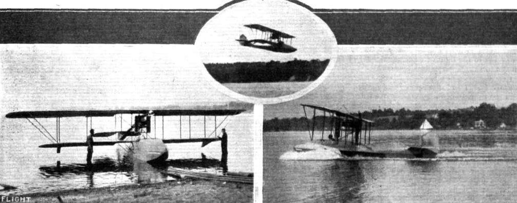
THREE VIEWS OF THE THOMAS FLYING BOAT. - Left: The machine at rest on the water. Right: Starting. Inset: The boat in flight.
Flight, August 28, 1914.
EDDIES.
The visitors to the Hendon Aerodrome on Saturday were treated to several very fine exhibition flights by Messrs. Beatty, Manton and Lillywhite. Beatty was first out, and gave some excellent demonstrations of steeply banked turns, spirals and switch-backs. He was followed a little later by Manton, who proved to have lost none of his skill in handling the bi-rudder 'bus. Shortly afterwards Lillywhite, who was on leave from the R.F.C., took up the same machine and executed some steep banks and dives, much to the delight of the spectators.
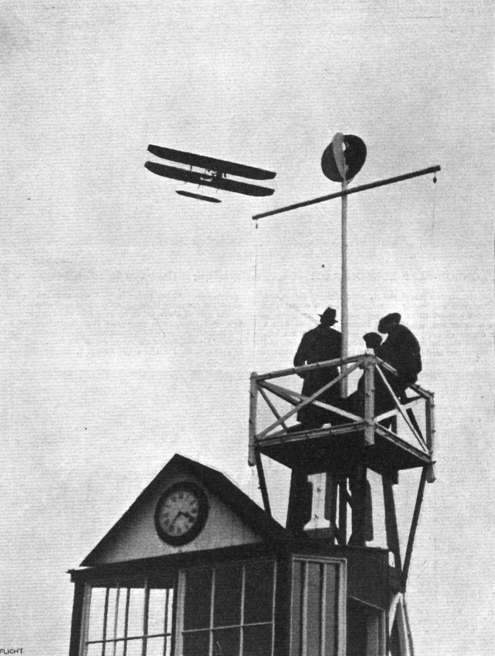
E. Baumann at Hendon Aerodrome passing over Pylon I on the Wright biplane.
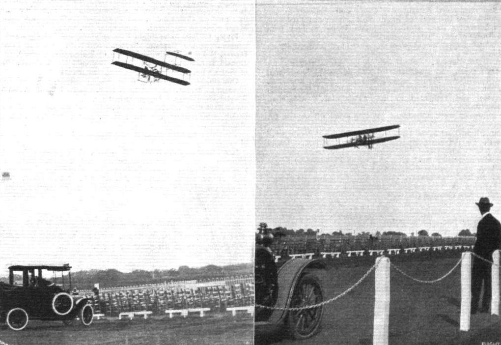
Mr. Beatty flying the Wright school biplane at Hendon recently.
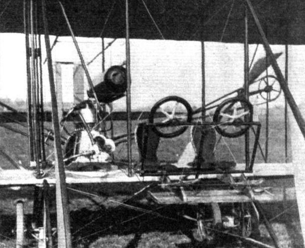
The dual control and power plant of the Wright flyer at the Beatty School, Hendon Aerodrome.
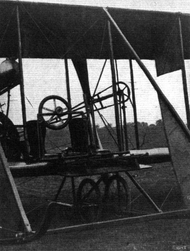
THE DUAL CONTROL ON MR. BEATTY'S WRIGHT BIPLANE. - As Mr. Beatty is accustomed to and prefers the original Wright control, the school machines are equipped with this type for the instructor, whilst the pupils' controls are similar to those most favoured by European designers, consisting of a hand wheel for the warp, mounted on a steel tube structure to which is connected the elevator, and a foot bar for the rudder. These are ingeniously interconnected with the Wright control so that both act simultaneously.
Flight, January 3, 1914.
AEROPLANE TYPES.
THE MODEL E WRIGHT BIPLANE.
SOME little time ago the Wright Factory at Dayton turned out a new type of biplane specially designed for exhibition work, which has given very satisfactory results in the air. It more or less follows the usual Wright practice, the only way in which it differ, being that a single propeller is employed instead of the two that have previously characterised these pioneer machines. There are, of course, several differences in constructional details necessitated by the new method of propulsion. One important feature consists of the rapidity with which it can be dismantled and vice versa. The planes are built up in three sections or panels, the centre one of which is carried on the chassis and bears the pilot and power plant. The latter consists of a water-cooled 30 h.p. 4-cylinder Wright motor, which is mounted on the lower plane alongside the pilot, on his right, and driving a seven-foot propeller by means of a single chain and a short length of shaft. The propeller is centrally situated at the rear of, and midway between the top and bottom planes, and its shaft is supported by a strut and three steel tie rods. The tail is carried by two pairs of V outriggers connected to the rear spar so that they are clear of the propeller. The tail is of the orthodox Wright pattern, consisting of a single elevator plane with a flexing trailing edge and a pair of directional rudders. Right in front of the machine are two "blinkers," which differ from those on other Wright models in that they are constructed of wood and are rigidly fastened at the bottom to the extremities of the skids. They are connected at the top by a thin tie rod, and the only other bracing required is a pair of diagonal wires from one to the other. The two outer cellules or panels are very easily detached from the centre one, the time taken to dismantle the machine for transport being well under fifteen minutes. The principal dimensions of this machine are:- Span, 32 ft.; overall length, 28 ft.; chord, 5 ft. 1 in.; supporting area, 316 sq. ft.; weight ready for the air, 730 lbs.
"VEE JAY."
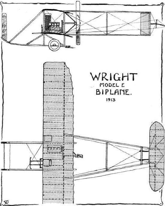
Flight, November 20, 1914.
THE NEW WRIGHT BIPLANE.
ALTHOUGH changes have been made in the Wright biplanes since the first radical change of discarding the front elevator, it is remarkable how the main characteristics have been adhered to, even in the latest model that has just been turned out from the Dayton works. As will be seen from the accompanying illustration of this new Wright biplane, in spite of the fact that a distinct departure from usual Wright practice has been made, it is still the Wright biplane of old. The principal alteration in the machine in question consists of the covered-in fuselage, following somewhat tractor biplane practice. This fuselage is of rectangular section tapering to a vertical knife-edge fore and aft, giving a good streamline form. Mounted in the nose is the engine, a 60 h.p. 6-cyl. water-cooled Wright, which is enclosed by a stream-lined bonnet that can readily be removed so as to give access to the engine. Pilot and passenger are seated side by side in the fuselage immediately behind the engine, and level with the leading edge of the planes. The latter are of the usual Wright type, set at a slight dihedral angle. The lower plane is divided into two parts and attached to the fuselage. Two propellers are mounted at the rear of the planes in the orthodox Wright style, and are driven by chains and shaft from the engine. The radiator for cooling the engine is mounted between the planes behind the pilot and passenger. A single-tail plane and elevator, similar to those on previous Wright machines, is mounted on the rear extremity of the fuselage, with the vertical rudders above. A pair of running wheels are mounted immediately underneath the lower plane, one on either side of the fuselage. Here another Wright characteristic is retained, for the wheels being close to the lower plane brings the machine very close to the ground. The principal dimensions of this machine are: Span, 32 ft.; overall length, 26 ft. 5 ins.; supporting area, 350 sq. ft.; speed, 70 m.p.h.; climbing speed (two up and fuel for 4 hrs.), 400 ft. per min.
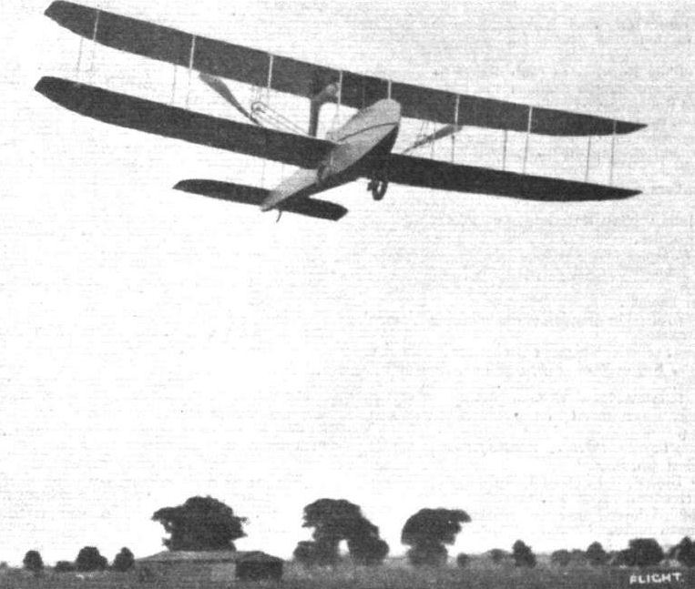
The new Wright biplane in flight.
Flight, January 17, 1914.
THE 60 H.P. WRIGHT AERO-BOAT.
THE popularity of the "flying-boat" type of hydroaeroplane in America is emphasized by the fact that the Wright Co. has now listed a machine of this type, known as model G. An interesting point in connection with this machine is that it is the result of the collaboration of two pioneers: Orville Wright, of course, being responsible for the aeroplane, while Grover C. Loening - one of the earliest experimenters with the flying boat - has contributed his share of the design in respect to the latter. Although this new Wright model is of the flying-boat type, it really possesses one or two of the characteristics of the single-pontoon type of machine - like, for instance, the Wright hydro-biplane described in FLIGHT for September 6th last. It is, in fact, a combination of both systems, possessing, it is claimed, the advantages of each without the disadvantages of either. This will readily be appreciated by a glance at the accompanying scale drawings, for it will be seen that the boat differs from the usual type in that, instead of stern-tapering to the tail planes, it is comparatively short, like a pontoon, yet at the same time the seaworthiness of the boat system is retained and the tendency of the pontoon to dive under water is reduced to a minimum. Again, the pilot and passenger are not in such close proximity to the water as in other boats, for they sit on the deck and are thus in a somewhat safer position in case of the boat being swamped by a wave. The boat consists of an alloy metal hull, built up on a strong wooden framework. It is 18 ft. long, with a maximum depth of nearly 3 ft. and a beam amidships of 3 ft. 7 ins. The bow is pointed and the stern tapers to a horizontal knife-edge. It is fitted with a single hydroplane step and the curvature of both fore and aft surfaces has been very carefully worked out. The boat is divided up into six watertight compartments and weighs, complete with engine-bed, seats and "cabin," only 305 lbs. The outer surface of the metal hull is specially treated to resist the action of sea water, &c. Two auxiliary floats, also of metal, are mounted on the leading edge of, and below the lower planes, one on either side of the boat, midway between the latter and the wing-tips. Mounted on the deck of the boat amidships are the main planes and the engine, and just forward of the leading edge of the lower plane are the two seats for pilot and passenger, side by side, whilst right in front is a cowl forming a cockpit. The main planes, as with the rest of the aeroplane component, follow the usual design of the Wright land machines, being built up of hollow spars and spruce ribs, the front spars forming the leading edges. Extending back from the rear spars is the orthodox Wright tail outrigger carrying a flexing elevator, somewhat larger than usual, mounted in front of which are the twin rudders. It will be seen that the engine is not mounted alongside the seats as in former models, but behind them, exactly in the centre of the lower plane. The power plant consists of one of the latest 60 h.p. 6-cyl. Wright motors (water-cooled), 4 3/8 ins. by 4 1/2 ins. bore and stroke, which drives a pair of propellers by chains in the conventional style. The propellers are placed a little higher in order to clear the water, and a corresponding alteration has been made to the elevator so that it comes level with the line of thrust. A foot throttle as well as a hand lever on the instrument board is provided for controlling the engine. The engine may be started by means of a hand crank situated just behind the seats, or a self-starter can be fitted if desired, whilst provision has been made for the fitting of a silencer. The machine is controlled in the air from either seat by the usual Wright system of levers, whilst the steering of the machine when hydroplaning is facilitated by two paddles mounted on the lower wing tips and operated from the cockpit. No front "blinkers" are employed, and instead of using a piece of string to indicate the machine's attitude, a small flag is carried by a mast in the bow, which, besides serving its useful purpose, adds to the appearance of the aero-boat. The total weight of the machine empty is 1,200 lbs., and the useful load is about 600 lbs. During the past few months Orville Wright has been carrying out some exhaustive tests with one of these aero-boats with entirely satisfactory results, a speed varying from 38 to 60 m.p.h. being obtained with two up. It rises from the water after a run of not more than 200 ft., and it is very stable in high winds.
Flight, March 7, 1914.
SOME AMERICAN FLYING BOATS.
Wright Flying Boat.
The Wright flying boat is the result of the collaboration of the Wright Company and Mr. Grover C. Loening, Mr. Loening being responsible for the boat, whilst the wings are of the usual Wright type. It will be seen that this flying boat differs considerably from those previously described, the main characteristics of this machine being the comparatively short boat, which does not carry the tail planes. These are carried on tail booms in a similar way to that employed in the usual Wright machine.
Perhaps the most interesting part of this machine is the boat hull itself, which is of novel design and construction. The hull is V-bowed, and the hydroplaning bottom consists virtually of two hydroplane surfaces, both presenting their most efficient angle to the water, while at the same time allowing for the best lifting angle of the planes, and the best thrust line combination. The rear plane has been studied with great care, since the angle of this plane for its highest efficiency requires consideration of the wave action induced by the front hydroplaning surface. The hull is of alloy metal, precaution being taken to make it impervious to the action of salt water by a special surface treatment. The hull, which is 3 ft. deep, 18 ft. long and 43 in. wide, weighs, fully equipped with engine bed, seats, dashboard and hood, 305 lbs. The hull is divided by bulkheads into six watertight compartments, and, since the motor and seats are set above the top of the watertight portion, the hull itself is really a sealed pontoon.
The seats are arranged side by side in front of the lower wings, inside a very neat cockpit, the arrangement of which is reminiscent of motor car practice. On a very neat dash in front of the seats is a complete set of instruments. Entrance to the cockpit is by side doors, and the upswept deck in front of the occupants' seats forms a very effective shield for the protection against wind and water spray. Instead of the usual "string" fitted on all Wright machines, a small flag is fitted at the bow, which serves to indicate the slightest tendency of the machine to side-slip. Double control levers are disposed in front of the seats, and the engine is controlled by a foot throttle combined with a hand lever throttle placed convenient to either operator. The engine, a 6-cylinder 60 h.p. Wright, fitted with an electric self-starter, is set low behind the seals and drives two propellers in the customary Wright fashion. The propellers are 8 ft. 6 ins. in diameter, and revolve at 600 revolutions per minute, at full throttle. The hand starting mechanism consists of a safety starter geared up from the engine. The fuel tanks are situated in a separate compartment in front of the engine. The aeroplane part of this machine follows standard Wright lines, the wings being built up in the usual way, of ribs with spruce flanges, and web blocks over hollow spars. As usual, the front spar forms the entering edge of the main plane. The usual Wright control is fitted, wing warping being employed for the maintenance of lateral stability. The elevator, which is of the usual Wright flexing type, has been raised approximately to the thrust line, and has an area of 48 sq. ft. The vertical rudders and elevator are carried by the conventional Wright tail-outriggers, which are tapered and hollowed out for lightness.
In addition to the main float or boat, two auxiliary floats are fitted. These are also of an alloy metal, and weigh 11 lbs, each. In order to facilitate manoeuvring while on the water, a curious paddle control system has been applied. The paddles are hinged to the front spars near the lower wing tip, and are operated by a separate system of wires running from the cockpit. When it is desired to turn to the left, the left-hand paddle is lowered and, causing a drag on the left side, turns the boat in that direction, whilst the opposite procedure is followed for making a right-hand turn. The characteristics of the Wright flying boat, of which scale drawings appeared in our issue of January 17th, are :-
Span of boat planes 38ft.
Length overall 28 ft. 4 1/2 in.
Chord 6 ft.
Gap 5 ft .
Total lifting surface 432 sq. ft.
Total weight 1,200 lbs.
Speed . 38to 60 m.p.h.
Flight, August 7, 1914.
THE LATEST WRIGHT FLYING BOAT,
THE subject of our scale drawings this week is a development of the Wright flying boat which was illustrated and described in our issue of January 17th last. A comparison of the scale drawings and other illustrations of the two machines will reveal that two main alterations have been effected in this latest product of the Wright Company. In the earlier model the engine was placed behind the pilot's and passenger's seats, whilst in the new machine it is mounted in the nose of the boat. Another innovation is to be found in the arrangement of the tail planes, which now follows more or less standard lines.
An interesting point in connection with the construction of the boat, and one which is not apparent from the illustrations, is the fact that this structure consists of two parts. The lower portion of the boat forming the hydroplane surfaces and step is virtually a sealed pontoon, the deck of which is shown by the dotted line in the side elevation of the scale drawings. The second part of the hull is formed by extending the sides of the pontoon upwards to form an enclosed body for the engine and occupants, protecting them very effectively from water spray. Constructionally, the boat is built up of an exceedingly strong framework of ash and spruce, covered with a thick metal sheeting, which has been carefully treated both inside and out to protect it against the deteriorating action of sea water. The streamline hood over the engine and around the seats has been made stronger than usual, and is now built up of a combination of metal and double planking of wood covered with fabric. Air is admitted to the step of the float by means of tubes running from the deck in the vicinity of the seats, through the watertight pontoon, and out at the step. These tubes serve not only to ventilate the step but drain the cockpit, in which the seats are located, of any water shipped in bad weather, in a similar manner to that employed in self-bailing lifeboats. With this provision there is no danger of flooding the cockpit, as the water will immediately flow off either through the tubes or out to the rear along the water-tight deck.
The engine - a six-cylinder 60 h.p. Wright - is mounted on top of the watertight deck and in front of the seats. Transmission is by means of a central shaft passing under the seats and thence by chains to the two propellers, which are, as usual, situated behind the main planes. As customary in Wright practice, one of the driving chains is crossed in order to make the propellers revolve in opposite directions. As in the land machines, the propellers are geared down and rotate at approximately 580 r.p.m., but in the reverse directions customary in previous Wright models.
A refinement not usually found on aeroplanes has been introduced in the transmission system by incorporating shock absorbers in the coupling between the engine and the driving shaft.
The metal covering over the engine is made in the form of two large sliding hatches, which, when removed, give access to the engine, and when closed serve as a practically watertight covering. As we have already mentioned, this covering has been considerably strengthened in the new machine, so that it is possible for the boat to plunge head on into a large wave without any danger of having the water flood the "engine room" with detrimental effect to the running of the engine, whilst the large removable hatches allow minor adjustments being made with the engine running.
As will be seen from the accompanying scale drawings, the main planes are of the same plan form as previous models, but differ considerably from previous Wright practice in that they are set at a slight dihedral angle, and have a section of much greater thickness than has been previously employed. The ribs are now made of solid I-section, and the depth of the spars has been considerably increased, resulting in a much stronger wing construction. The very highest grade of steel wire is used throughout, and wire strainers and other joints, apt to become loosened, have been almost entirely eliminated, and all the important lift wires, as well as the control cables, are in duplicate.
Under the tips of the lower wing are mounted auxiliary floats, attached to the wing spars by strong steel braces. In the previous model, it will be remembered, paddles were fitted to the wing tips for the purpose of steering the machine on the water, but as these were found to be unnecessary they have not been used in the new machine, which answers the rudders well when taxying.
One of the features which have characterised Wright machines has disappeared, i.e., the flexing tail plane. In its stead is fitted a fixed tail plane bolted to the upper tail booms, to the trailing edge of which is hinged the elevating plane. Below the tail planes, and pivoted around two steel tubes, forming at the same time the rear struts of the tail outrigger, are the twin rudders, which also differ in shape from those of earlier Wright machines.
Dual control is fitted, and provision has been made for mounting either standard Wright controls or the new Wright wheel control.
The weight of the machine empty is 1,300 lbs., and the speed variation ranges from 40 to 60 m.p.h.
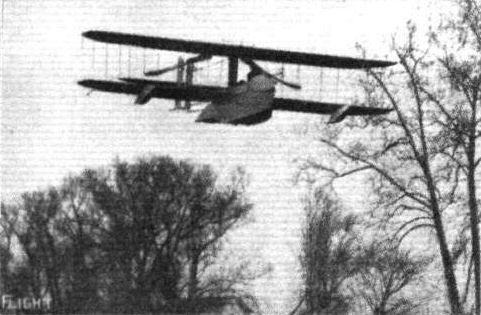
A view of the Wright aero-boat in flight.
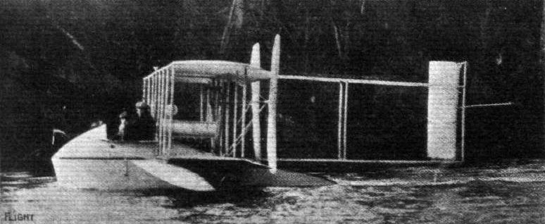
The new Wright aero-boat, as seen from the side.
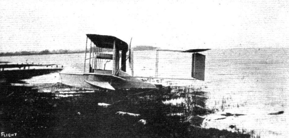
The Wright flying boat on the beach.
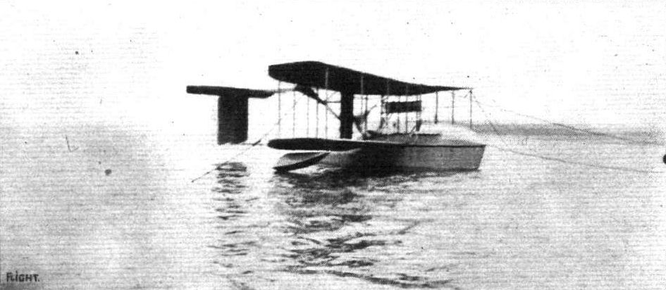
The latest Wright flying boat at its moorings.

Photograph showing how admittance to the pilot's cockpit is gained through a small side door similar to those of a motor car.
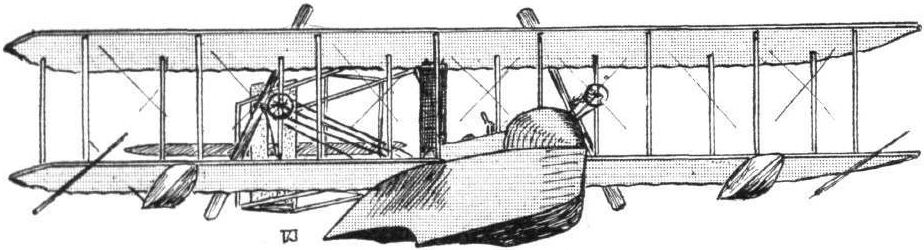
Sketch of the Wright aero-boat.
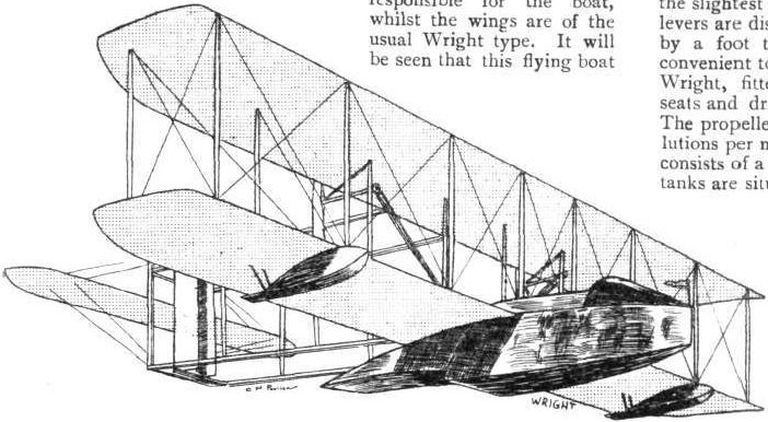
The Wright flying boat.

THE NEW WRIGHT AERO-BOAT. - Plan, side and front elevation to scale.
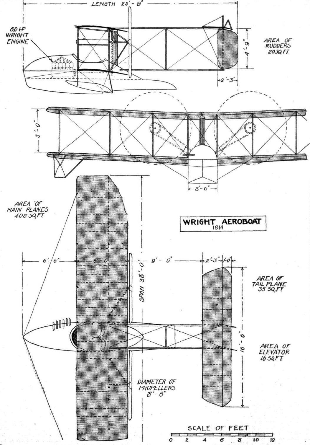
THE WRIGHT AEROBOAT. - Plan, front and side elevations to scale.
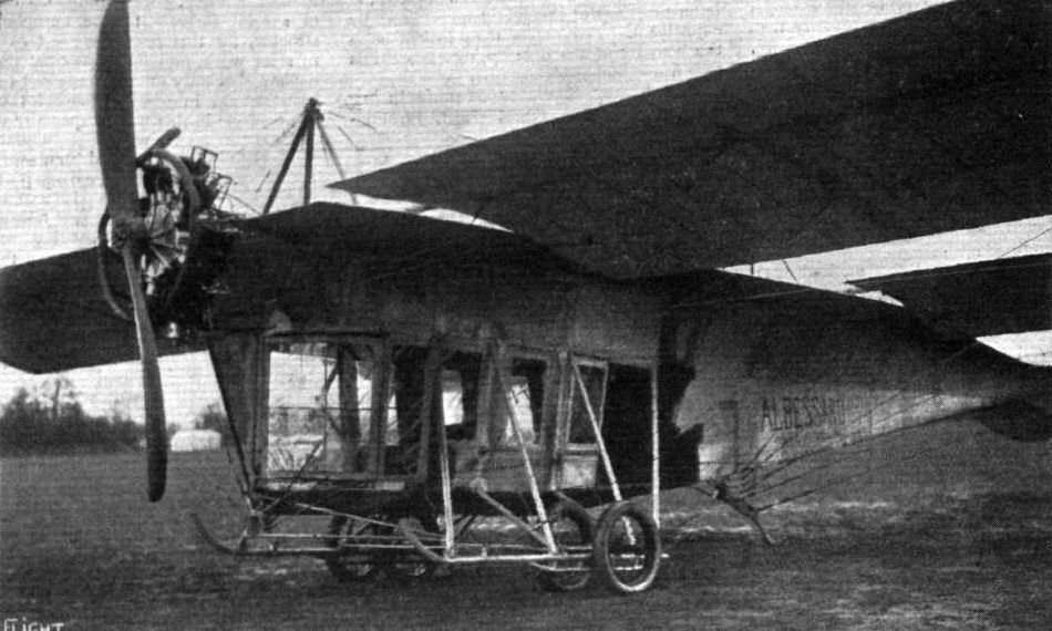
View of the cabin on the Albessard monoplane, which accommodates three passengers.
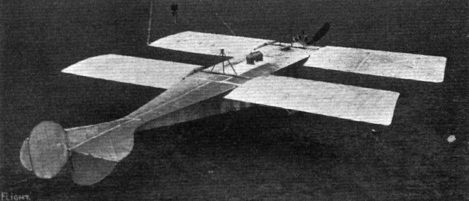
View from above of the Albessard double monoplane, which is fitted with a pendulum automatic stability device. The span is 11 metres and the overall length 12 metres. It is fitted with a 100 h.p. Anzani motor, and weighs 750 kliogs. empty.
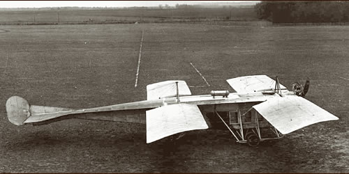
From the beginning of aviation people had fantastic visions of future possibilities and a few made first efforts to bring them into practice. Like Albessard who built a tandem monoplane with a passenger cabin in 1912. He gave up on the aircraft after unsuccessful tests which were performed with only the pilot aboard.
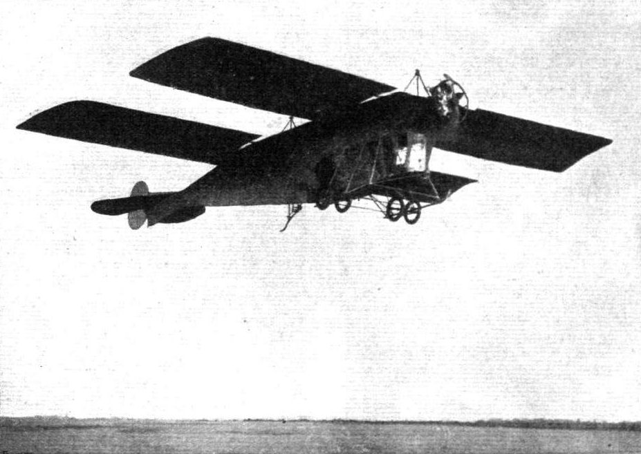
The Albessard monoplane, which was illustrated in FLIGHT the week before last, in the air.
Flight, May 9, 1914.
THE SANCHEZ-BESA BIPLANE.
THE subject of our scale drawings this week, the Sanchez-Besa biplane, which paid a brief visit to Hendon aerodrome during last week-end, is similar in its general arrangement to the machine exhibited at the last Paris Aero Show, when it was fully described in these columns. The chief alteration appears to be that this machine is fitted with an 80 h.p. Salmson engine, whereas the one at the Paris Show had a Renault engine. Also the tail planes have been slightly altered, so that now the rudders are mounted on and move with the elevator. The machine is built of steel almost throughout, and is mainly characteristic on account of its rather unusual type chassis, which consists of two stub axles universally pivoted to the rear end of the very long ash skid, and carrying two large diameter wheels which are sprung by means of rubber shock absorbers attached to telescopic tubes running from the outer end of the stub axle to the rear end of the lower longerons of the nacelle. The front end of the skid is supported on a structure of three steel tubes. Two smaller wheels mounted on a short tubular axle, prevent the machine from turning over on her nose on landing.
The nacelle is built up in the usual way, and provides accommodation for pilot and two passengers, the latter being seated side by side between the pilot's seat and the leading edge of the wings. A wind shield in the nose of the nacelle deflects the air above the heads of the occupants. Behind the passengers' seat and inside the nacelle is mounted a large petrol tank, containing a supply sufficient for a flight of 4 1/2 hours' duration.
The engine, an 80 h.p. Salmson, is mounted between double bearings in the rear of the nacelle, and drives through a spur reduction gearing the large diameter propeller which is situated behind the main planes. The propeller-shaft, which is mounted some seven or eight inches above the upper longerons of the nacelle, is supported on a structure of steel tubes, and has at its rear end a combined thrust and journal ball-bearing. The engine can be started from the passengers' seat by means of a starting handle, thus doing away with the usual swinging of the propeller.
The main planes, which have a comparatively small gap in relation to the chord, are built up of wooden ribs over steel tube spars. Inter-connected ailerons are fitted to both upper and lower planes, and the chord of the ailerons is greater at the tip than at their inner ends in order to render them more efficient. The tail planes are carried on an outrigger formed by four steel tubes, and are unusual in that the two divided rudders are mounted on and move with the elevator, so that when the latter is moved up or down the rudders move backwards and forwards with it. This arrangement necessitates a rather unusual control gear, which consists of the usual central universally pivoted hand lever which operates the elevators through a series of quadrants underneath the nacelle. By means of these quadrants the movement of the elevator is geared up so that for a small movement of the hand lever the elevator is rotated through a comparatively large arc. The whole control gear seems unnecessarily complicated, and it is a question whether a different type tail, which would do away with the use of the quadrants, would not be an improvement. However, the present system appears to work quite satisfactorily, and the machine certainly answers the controls very well, doing right angle turns in apparently less than her own length.
When doing a turn with the rudders only these do not seem to be any too large, but by using the ailerons in conjunction with the rudders exceedingly sharp turns can be effected. The machine appears to be perfectly stable spirally, in spite of the comparatively large side area of the nacelle in front of the centre of gravity, and last Sunday, at Hendon, the pilot - Delaporte - flew the machine in a high wind with both hands off the controls.
A refinement worth noticing in the machine, and one illustrated by the accompanying sketches, are the wheel brakes fitted on the rear wheels. By means of these brakes, which are operated from the pilot's seat, the machine can be held back by the pilot whilst running the engine all out, so that it is possible, by the aid of these brakes, and the starting handle behind the passengers' seat, to start the machine without any outside assistance whatever, a feature which should prove useful for cross-country work where, after having made a forced landing en route, experienced assistants are not always available, and where the help of inexperienced, though willing, assistants may easily cause considerable damage to the machine. Another advantage of the wheel brakes is that on making a landing in confined areas the machine can be stopped after a very short run along the ground; in fact, it appears to be possible to bring it to a standstill after a run of about twice its own length.
The weight of the machine empty is 1,750 lbs., her maximum speed is 65 m.p.h., and the minimum flying speed about 35 m.p.h.
The machine described above has already gone back to France, but we understand that a similar machine, fitted with a 130 h.p. engine, will be coming over here shortly.

A view from above of the Sanchez-Besa biplane.
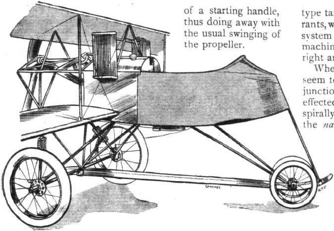
Nacelle and chassis of Sanchez-Besa biplane.
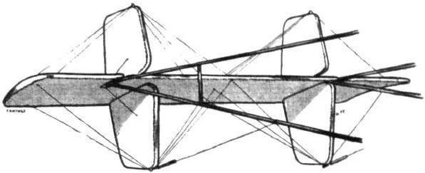
Tail planes of the Sanchez-Besa biplane.
Left: Inter-plane strut attachment and control-cable pulleys on Sanchez-Besa biplane. On the right: Detail sketch of wheel brake.

SANCHEZ-BESA BIPLANE. - Plan, side and front elevation to scale.
Flight, August 28, 1914.
EDDIES.
Among the pilots who are leaving Brooklands is Mr. Harold Treloar, of Ballarat, who, as recorded in "Eddies" some time ago, obtained his brevet at the Bristol school after only three weeks' tuition, and who has since been taking an extended course at the Bleriot school in order to get some experience in the handling of a monoplane. Mr. Treloar is leaving for Australia on the R.M.S. "Osterley" this week, and hopes, as soon as the war is over, to purchase a Bleriot monoplane of the same type as the machine that he has been flying at Brooklands lately, and which he considers ideal for the pilot-owner. It is to be hoped that Mr. Treloar may arrive safely at his destination, and soon be able to help on the good work of assisting the cause of aviation under the Southern Cross. Bon voyage!

Mr. Harold Treloar in his Blerlot at Brooklands.
Flight, January 10, 1914.
FLYING AT HENDON.
<...>
On Friday, the 2nd inst, some New Year's records were put up by Gustav Hamel, who looped the loop with Miss Trehawke Davies on his 80 h.p. Morane-Saulnier monoplane. This not only constitutes the first time that a pilot has looped the loop with a passenger in this country, but it is the first time on record that one of the fair sex has participated in this feat. Previous to looping the loop with Miss Davies, Hamel made a number of loops, semi-loops, and steeply banked turns and many other startling evolutions. He also took up Miss Gladys Cooper, the popular actress, for a flight. At four o'clock Miss Davies and Hamel were securely strapped in their seats. He climbed to a height of 1,000ft., and at this height executed one loop and what has been called a "side loop," in which he turns the machine over sideways until it is on its back, and then nose-dived to regain the normal position. From the passenger point of view this performance was all the more remarkable when it is remembered that Miss Davies had practically left her sick bed to loop the loop, and, in fact, after it was all over she returned home, where her doctor was to perform a minor operation.
<...>
EDDIES.
So Miss Trehawke Davies has been the first woman to loop the loop after all. Keen on it? Well, she left abed of sickness, drove to the aerodrome, looped the loop - or did the Apple Turnover, as they call Hamel's stunt down Hendon way - and was back in bed when the doctor called to perform a minor operation. Oh! no, not keen; meant to be first, that's all.
Flight, March 14, 1914.
WHAT THERE WILL BE TO SEE AT OLYMPIA.
THE EXHIBITS.
Bleriot (L. Bleriot). (60.)
M. BLERIOT will have a most comprehensive exhibit, no less than four machines being shown, as well as sand yachts.
The first of these is the Bleriot No. XI-2 tandem two-seater monoplane, on a similar machine to which the then world's distance record with a passenger of 815 miles in one day, and the world's height record of 16,326 ft. were established in 1913. The same type of machine was used by Vedrines in his flight from Nancy to Constantinople, and by Bider in flying over the Pyrenees and the Alps. This machine, the essential features of which are already known to our readers, when ready for transport, occupies a width of 5 ft. 7 ins. only, and is 6 ft. 2 ins. high, while four mechanics can re-erect the wings ready for flight in half an hour.
<...>
Flight, March 21, 1914.
THE OLYMPIA EXHIBITION.
THE EXHIBITS.
BLERIOT L. (BLERIOT). (69).
NEATLY displayed on the largest stand at the Show are the Bleriot monoplanes - a tandem two-seater of the well-known type, a hydro-monoplane, and a single-seater military monoplane.
<...>
The 80 h.p. Tandem Two-seater, which otherwise appears to be similar in every way to those already in use in this country, and with which the majority of our readers are familiar.
The fuselage is of a similar construction to that of the Visibility type machine, but is slightly longer. The pilot's and passenger's seats are arranged in tandem, the pilot occupying the front seat, which is situated between the front and rear spars. The passenger's seat is immediately behind that of the pilot, while the trailing edges of the wings have been cut away near the body in order to give the passenger a better view in a forward and downward direction.
The chassis is of the usual Bleriot type, but joins the body behind the engine instead of in front of it, as in the single-seater. The cylindrical oil and petrol service tanks are mounted longitudinally inside the fuselage between the pilot and engine, whilst the main petrol tank is carried in the fuselage behind the passenger's seat. In the machine shown, this tank is covered by a streamline cowl.
The tail planes are as usual, consisting of a fixed tail plane mounted under the rear end of the fuselage and graced by steel tubes, to the trailing edge of which is hinged the divided and negatively cambered elevator. The rudder is partly balanced by a portion of it projecting in front of the rudder bar.
A swivelling tail skid carried on a structure of steel tubes, and sprung by means of rubber bands, protects the tail planes against contact with the ground.
In addition to the three machines described above, there is shown one of the aeroplages, or sand yachts, which have attained no small measure of popularity in France, and which would provide quite a lot of sport if introduced at some seaside resorts. It consists of a framework of steel tubes, carrying the four wheels; of which the front ones have the wider track than those at the rear. On top of these transverse tubes are mounted two ash members running longitudinally from which the seats are slung. A steering column slopes backward to the driver's seat, and carries at its upper end an ordinary steering wheel, whilst at its lower extremity it has a bobbin, over which cables piss to the rear wheels via two pulleys on the ash members. The whole affair is very lightly built, and should be capable of a fair speed in a wind.
Flight, April 4, 1914.
BRITISH NOTES OF THE WEEK.
Mr. Hewitt at Rhyl.
ON Tuesday of last week Mr. Vivian Hewitt flew on his rebuilt Bleriot for about an hour round about Rhyl, and went up the Vale of Ciwyd as far as Rhuddlan and back. On Thursday he was up again over Rhyl for 1 1/2 hrs., and also went over to Abergele, about five miles from Rhyl. The next day he was up again for one hour, and had as passenger a small black lamb, this being, no doubt, the first time that a lamb has been carried in an aeroplane. A descent was made on the shore at Rhyl, in order that the accompanying photo might be taken. The lamb seemed to take it quite as a matter of course, and trotted back to its mother after the flight as if nothing had happened.
Salmet's Paris-London Trip.
A FINE flight from Paris to London was made by Mr. H. Salmet, accompanied by T. Elder Hearn, on a Bleriot monoplane, on Saturday last. Buc was left at 10 a.m., and a nonstop trip made to Folkestone, which was reached about half-past twelve. Resuming at 4 p.m., good progress was made until nearing the Metropolis when the machine ran into mists, and a descent had to be made at Staines in order to ask the way. Eventually Hendon was reached about ten minutes past six.
Flight, April 25, 1914.
OVER THE ROYAL YACHT IN MID-CHANNEL.
By B. C. HUCKS.
ONE of the jolliest trips I have ever made. That's how I feel about my flight last Tuesday, when I was successful in bringing to London the first pictures of Their Majesties' Channel crossing and arrival at Calais.
I first heard of the project on Friday last at 2 p.m., when Mr. Harold Perrin took my manager, Mr. J. C. Savage, and myself along to the Savoy to meet Mr. Hugh Spottiswoode of The Sphere and Mr. Croxton of the London Coliseum, the two gentlemen who were working the "stunt." Final details were settled on Saturday mid-day, a float procured in case the machine dropped in the Channel and my 80 Bleriot two-seater packed up at Coventry where I looped on Easter Monday and trained to Folkestone, the point decided on for the start of the flight, owing to Dover being within prohibited area.
On Sunday a landing ground at Calais was chosen and a starting ground at Folkestone. The latter was a field at Capel, right on the top of the cliffs and about three miles from Folkestone. My machine arrived at Folkestone on Monday midday, was conveyed by motor to the ground and was erected and ready for flight by 5 p.m. I made a trial trip over the sea front at Folkestone about six o'clock the same evening, with Mr. Harold Pontefract in the passenger seat, and found everything in order. On Tuesday morning after a trial flight with the operator to get him used to his peculiar position - he faced towards the tail - I started off across the Channel at exactly 11 a.m. in brilliant sunshine and very little wind, exactly half an hour after the departure of the Royal Yacht from Dover. It took me some time to pick up the Royal Yacht as there was a considerable mist on the surface of the sea, but after about fifteen minutes' flying, I noticed a haze of smoke and as this was the only sign of activity in the neighbourhood I made for it and discovered my quarry. The French cruisers had already joined the escort, and to give my operator every facility I dived down to about 400 ft. and enabled him to get a fine picture of the mid-Channel scene.
I circled the fleet completely on three occasions, being then right out of sight of land. As we were nearing Calais I hovered about and flew over Calais Harbour at the precise moment of the entry of Their Majesties' Yacht, when my photographer obtained what turned out to be a most magnificent and novel film. I then made direct for the Calais Aerodrome, flying over the town at 800 ft, I landed at 12 noon, when I was presented with a bouquet from the Mayor of Calais and also learnt that I was the first English airman to land at Calais.
The operator then extracted the exposed film which I fixed in the passenger seat of my machine together with the bouquet, and at 1.45 I started off for Hendon. I struck the English coast at the exact point of my departure, followed the railway line to Ashford, and on reaching the outskirts of London, I took last year's Aerial Derby course to Hendon, where I arrived at 2.35. I had covered the 125 miles in n o minutes. The journey overland was a very bumpy one, there being a terrible lot of remous owing to the extreme heat of the sun.
On landing, the film was handed to a representative of the Warwick Bioscope Chronicle Film, and rushed off to Charing Cross Road, where it was developed, a print made, and a complete record of the King's journey from London to Calais was shown at the matinee performance at the Coliseum at 5.20. Actually, the film was delivered to the Coliseum at 4.45.
Flight, June 26, 1914.
EDDIES.
Mr. Summerfield, of Melton Mowbray, who has recently been flying the Watson rocking wing machine at Buc, had a narrow escape whilst flying his Bleriot monoplane recently. He was coming down in a steep spiral, and, when trying to flatten out at a height of about 50 ft., found that one of his rudder control wires had come adrift, thus rendering the rudder useless. Taking his feet off the rudder bar and placing them on the tank he awaited the smash. The machine struck the ground with great force and was totally wrecked, but Mr. Summerfield escaped practically unhurt. He is of the opinion that had he kept his feet on the rudder bar he would have broken his legs.
Flight, May 9, 1914.
EDDIES.
Marcel Desoutter, the young pilot who, it will be remembered, had his leg injured in a smash on his monoplane last year, made a cross-country flight from Brooklands to Hendon on Sunday last. Starting from Brooklands at 6.10 p.m., on Lord Edward Grosvenor's Bleriot monoplane, he set his course for Hendon, after first having made one or two preliminary flights round the Brooklands aerodrome. Owing to a slight ground mist he lost his way, however, and came down in a field to ascertain his whereabouts. As he was afraid to stop his engine he kept switching on and off whilst shouting to some people who had rapidly gathered in the field when they saw him come down, to tell him in which direction lay Hendon. It was very amusing, Desoutter tells me, to see the nervousness of the people. Whenever he switched off his engine the people drew a little closer, but every time he switched on again they scattered like a flock of chickens, and he had the greatest difficulty in getting one of the men to come close enough to hear what Desoutter wanted. He was then told to follow the railway line, which would take him right past the Hendon aerodrome, where he did not arrive until 7.30, owing to the delay caused by having to come down and enquire his way.
It appears that Desoutter is going to profit in a somewhat unexpected way by his mishap last year, in which he lost one of his legs. When he got well he had a wooden leg made, but finding this a bit too heavy for his liking, and being of an ingenious turn of mind, he set to work to make one himself, and a very good job he has made of it. The leg is made of a framework of a special aluminium alloy covered with leather, and he has succeeded in getting down the weight as low as 2 lbs. Since it became known how successful Desoutter has been in making this leg, he has had a great number of letters from people who have lost one of their legs asking him to furnish them with legs of a similar construction to that which he has made for himself, and he has now patented the process of making artificial legs.
"AEOLUS."
Flight, May 22, 1914.
THE AERIAL DERBY.
THE PILOTS AND HOW TO RECOGNISE THE MACHINES.
No. 6. The 80 h.p. Bleriot Monoplane
will be easily recognised, as it has rounded wing tips and differs from the other monoplanes entered in that the rear portion of the fuselage is left uncovered.
THE MACHINES AND HOW TO RECOGNISE THEM.
No. 6. The 80 h.p. Bleriot two-seater is already so well known as to need little description here. The pilot's and the passenger's seats, it will be remembered, are arranged tandem fashion, the passenger occupying the rear seat, just behind the trailing edge of the wings, from where he obtains an excellent view of the country beneath.
Flight, June 5, 1914.
BLERIOT ACTIVITY.
ALTHOUGH the Bleriot works at Brooklands have been in operation a few weeks only, M. N. Chereau, their general manager, has already made an excellent start by turning out a number of 80 h.p. two-seater British built Bleriots. These machines, which were ordered by the British Government, are built at the Brooklands works throughout, and the workmanship is equal to, if not indeed better, than that of the French built machines. As one would expect from so capable a manager as M. Chereau, the works are excellently arranged.
Five of the hangars have been turned into one large erecting shop, the size of which may be easily realised by a glance at the accompanying photographs. About half a score of machines may be erected at one time, whilst in the woodwork department adjoining the erection shop are to be found all the latest improvements in woodworking machinery. The various departments are in charge of experienced foremen, each of whom is an expert in his own particular line of work.
The hangars adjoining the works have been turned into roomy well lighted offices, whilst another hangar is at present being turned into club rooms for the Bleriot pupils. The front portion of this hangar will, when finished, be a lounge in which pupils can discuss the events of the day over a pipe, and at the back of this lounge the building will be divided into a number of small cabins, each assigned for a pupil, so that those of the pupils who wish to do so, may bunk in his cabin so as to be at hand early in the morning, and thus save valuable time, and draw advantage of the morning calms without wasting time in getting down to the aerodrome. We understand from M. Chereau that arrangements have been made with the authorities to train officers of the reserve and to offer facilities for those officers who have already obtained their brevets to practice at the Bleriot school. With the works close at hand to effect repairs, and with the extensive accommodation for the personal comfort of the pupils, the Bleriot school should become very popular both among officers and civilians.
The instruction will be in the hands of M. Jules Teulade-Cabanes, who has been appointed chief instructor, whilst Mr. Edwin Gower, who has been flying Bleriots at Buc, will be chief pilot. Several 80 h.p. two-seaters of the new type will be manufactured shortly in addition to a number of school machines ranging from 50 h.p. brevet machines down to pingouin taxying machines.
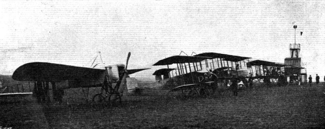
A start for a cross-country race at Hendon Aerodrome with the opening of the present season.
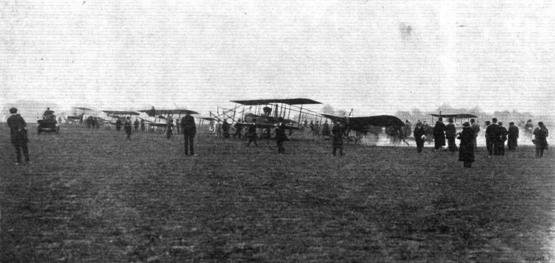
THE START FOR THE AERIAL DERBY AT HENDON AERODROME. - Filip Bjorkland running his engine on his Bleriot just prior to getting away.
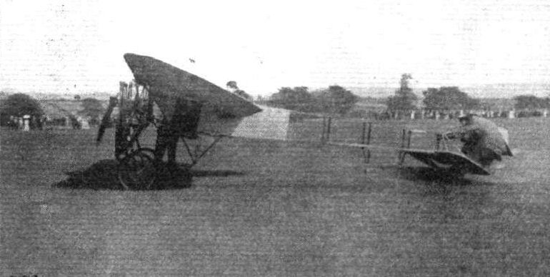
Mr. S. Summerfield about to start on a flight at Melton Mowbray on his Bleriot. Note the little mascot cat above the wings.
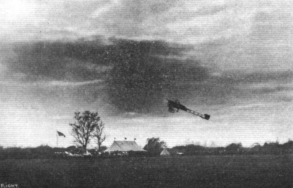
A sharp rise by Mr. B. C. Hucks on his Bleriot during his recent visit to Leicester for exhibition flying.
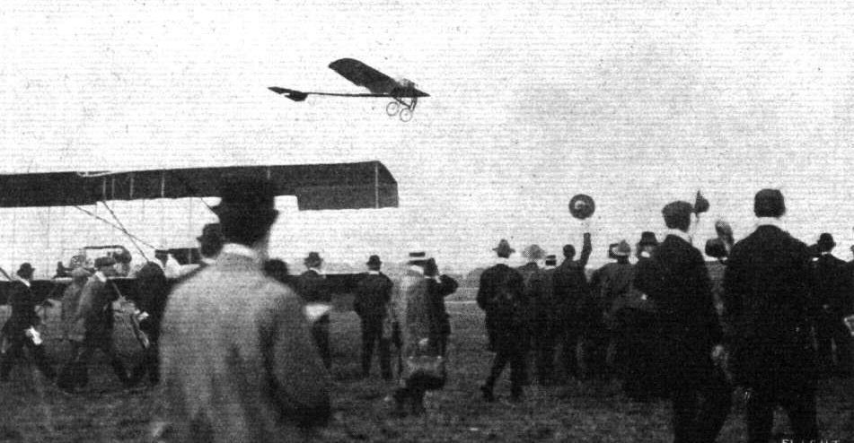
Sopwith on his Bleriot, the first man back to the London Aerodrome on Saturday, June 8th, 1912, in the First Aerial Derby, who, however, was disqualified for passing inside the Purley control.
Louis Noel on the Bleriot overtaking Louis Strange flying the Grahame-White Boxkite during a race at Hendon on 14 March, 1914.
RACING AT HENDON. - The second heat of the Speed Handicap on Whit Saturday. From left to right the machines are: Messrs. R. J. Lillywhite (G.-W. twin rudder), Verrier (Maurice Farman), W. Birchenough (G.-W.-Maurice Farman), and L. Noel (Bleriot).
The two-seater Bleriot Monoplane (No. 6).
In connection with M. Bieriot's candidature for the Seine General Council, as we mentioned last week, Bleriot monoplanes were utilised for the dissemination of handbills and other election literature on behalf of M. Bleriot. Above is seen one of the machines used at Buc, on the left being M. Bleriot and in the pilot's seat M. A. Bidot, who piloted this 80 h.p. military machine in a 90 kilometre wind, the handbills being thrown out by Mr. T. Elder Hearn, who is also seen in the above machine.
Tandem two-seater Bleriot.

The above snaps are of considerable historical interest from the fact that they show the scene at Buc uoon the occasion when Pegoud for the first time "looped the loop" on his Bleriot. On the left Pegoud is seen pointing out to those concerned the exact spot where he Intended to make his first loop. In the centre picture is the late M. Perreyon, and in the righ-hand picture from right to left MM. Pegoud, Domenjoz and Perreyon.
THREE HISTORIC MACHINES IN LINE AT HELIOPOLIS. - In the centre is Marc Pourpe's 60 h.p. Gnome-Morane-Saulnier, which he flew from Cairo to Khartoum and is now flying back - this is the identical machine on which Garros crossed the Mediterranean on the left is Vedrines 80 h.p. Gnome Bleriot which was flown from Paris to Cairo; while on the right is Bonnier's 80 h.p. Gnome-Nieuport, which has also been flown from Paris to Cairo.
Two Bedouin watchmen, known locally as Gafirs, on guard over Mr. W. Oswald Watts' Bleriot at Heliopolis.
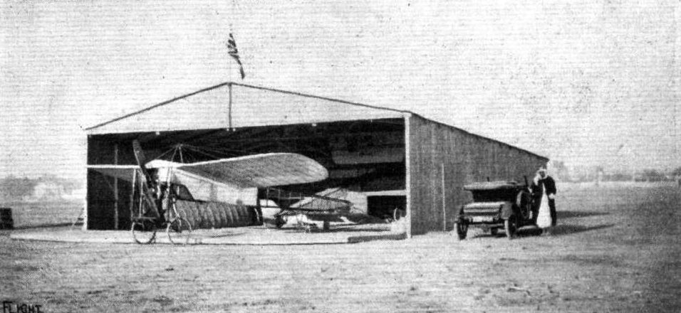
FLYING AT HELIOPOLIS. - The first Hangar in Egypt to fly the British flag. The machine in front is Mr. W. Oswald Watts' 60 h.p. Blerlot single-seater, and behind inside may be noticed Marc Pourpe's Khartoum 60 h.p. Morane-Saulnier on which, half an hour after the photograph was taken, he started away and flew to Suez in 1 hr. 10 mins., very fine going.

A couple of interior views of the new British Bleriot works at Brooklands. On the left a view of half a dozen machines in the shop, and on the right a portion of the wood-working department is seen.
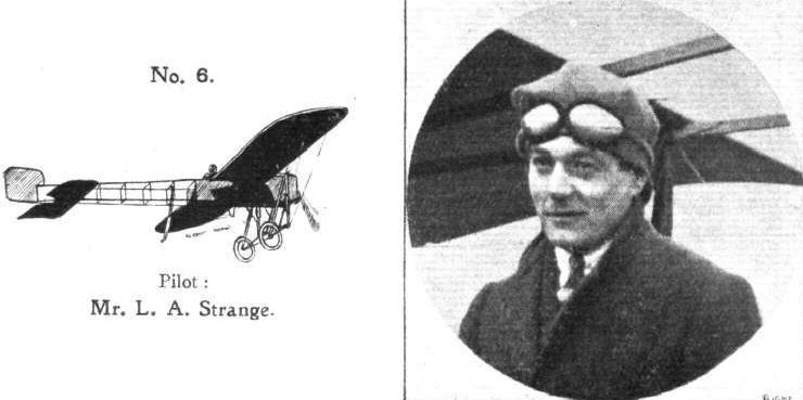
Pilot: Mr. L. A. Strange.
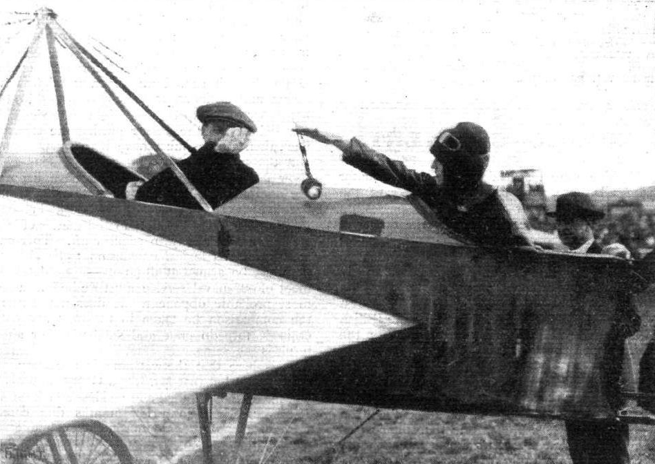
Miss Trehawke Davies handing Mr. Gustav Hamel his goggles prior to ascending with Mr. Hamel in his monoplane at Hendon on Friday, January 2nd, for the purpose of looping the loop, Miss Davies being the first woman to go through this remarkable experience in Great Britain.
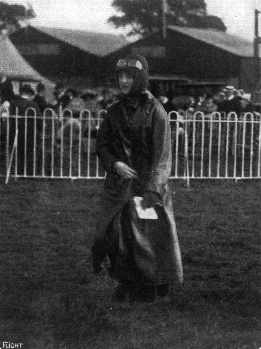
MISS TREHAWKE DAVIES.
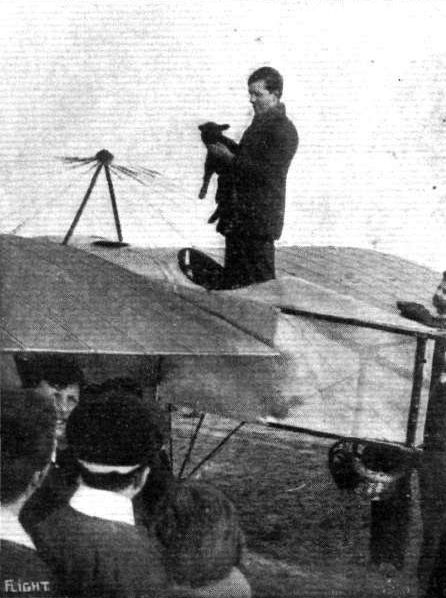
Mr. Vivian Hewitt and his lamb passenger.

Mr. T. Elder Hearn, who was just taken his brevet in France, after 4 hrs. 40 mins. work at the Bleriot School at Buc. He writes that after some further practice he intends to try the "loop" and thereby score a record for rapid advance in piloting, and hopes to follow it up immediately afterwards with a flight from Paris to London.
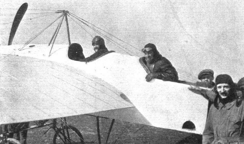
Mr. Salmet and his passenger, Mr. T. Elder Hearn, just before their flight from Buc to Hendon last week. Mr. Hearn hopes to make the same trip as pilot himself in about three weeks' time.
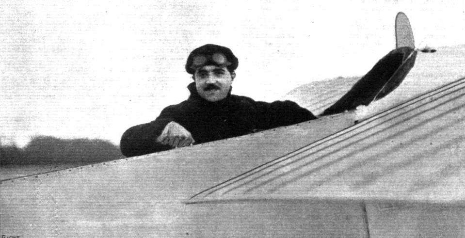
Marcel Desoutter, who is now flying again, about to leave Brooklands on Sunday last for Hendon on Lord Edward Grosvenor's Bleriot.
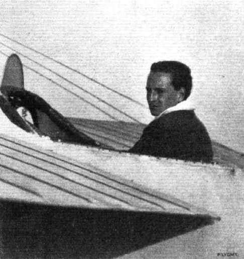
Mr. R. Skene in the pilot's seat of Lord Edward Grosvenor's Bleriot.
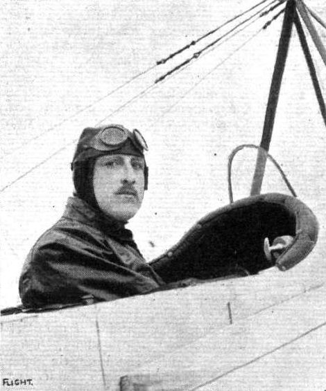
Mr. Landry, the first French Canadian to take his F.A.I. brevet at Buc.

OUR FLIGHT OFFICERS AT THE FRONT. - Lieut. James Valentine, R.F.C., with his Bleriot at ---.
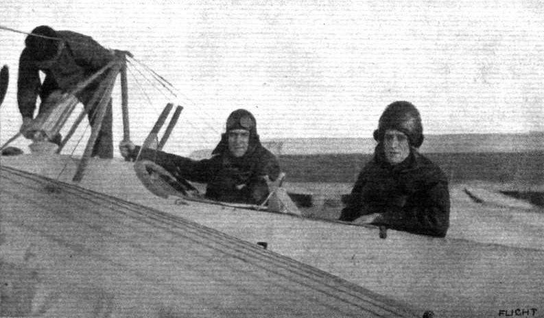
Capt. Oswald Watt (now with the French Army) starting for a flight, with Mr. Wallace Barr as passenger, from the aerodrome at St. Cyr.
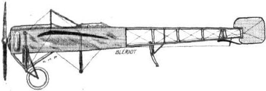
The 70 h.p. Bleriot two-seater monoplane.
Flight, March 14, 1914.
WHAT THERE WILL BE TO SEE AT OLYMPIA.
THE EXHIBITS.
Bleriot (L. Bleriot). (60.)
M. BLERIOT will have a most comprehensive exhibit, no less than four machines being shown, as well as sand yachts.
<...>
The third type of machine is similar in design to the No. XI-2 monoplane referred to above, the principal difference being in its adaptation for sea service by the substitution of floats for the ordinary wheels. The landing gear follows the usual Bleriot practice, excepting that the struts are placed wider apart to as to give greater stability to the machine on the water, and the floats are capable of articulating independently of one another, to allow of ample freedom of movement when landing or riding a rough sea.
<...>
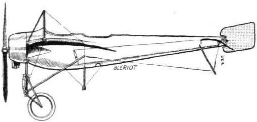
The 80 h.p. Bleriot cocque monoplane.
Flight, March 14, 1914.
WHAT THERE WILL BE TO SEE AT OLYMPIA.
THE EXHIBITS.
Bleriot (L. Bleriot). (60.)
M. BLERIOT will have a most comprehensive exhibit, no less than four machines being shown, as well as sand yachts.
<...>
In the remaining machine, which made its appearance at the Paris Aero Show (See FLIGHT December 20th, 1913), is a "coque fuselage " monoplane, and is a speed machine, capable of travelling at 75 miles per hour and climbing at the rate of over 450 ft. per minute. It normally carries sufficient fuel to last for four hours, and is a two-seater, the observer being placed behind the pilot, and by lying down in the fuselage can observe the country over which the machine may be travelling, through an aperture in the bottom of the coque. A speaking tube, fitted with a microphone, is fitted to enable the passenger to communicate with the pilot.
The Bleriot sand yachts will complete a very interesting exhibit.
Flight, March 21, 1914.
THE OLYMPIA EXHIBITION.
THE EXHIBITS.
BLERIOT L. (BLERIOT). (69).
NEATLY displayed on the largest stand at the Show are the Bleriot monoplanes - a tandem two-seater of the well-known type, a hydro-monoplane, and a single-seater military monoplane.
<...>
The 80 h.p. Seaplane does not differ materially from the machine exhibited at the Paris Show and fully described in our report at that time. One of the chief alterations appears to be a shortening of the chassis by carrying the cross member under the lower longerons instead of, as then, under the upper longerons.
The chassis is illustrated by the accompanying sketches and photographs which are self explanatory.
The two main floats, of the non-stepped type, have been built by the well-known Tellier firm.
A small float protects the tail planes against contact with the water, and a water rudder mounted on an extension of the rudder post enables the machine to be steered when taxying at low speeds.
The two seats are arranged tandem fashion as in the land machines, but appear to have been moved closer together, no doubt with a view to reducing the longitudinal moment of inertia. The same applies to
<...>
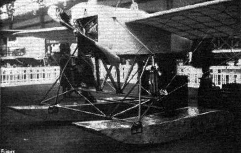
Chassis of the Bleriot hydro.

The 80 h.p. Bleriot seaplane.
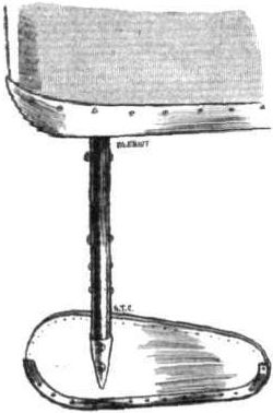
The water rudder on the Bleriot hydro.

Attachment of chassis forks to float on Bleriot hydro.

Attachment of front chassis members on Bleriot hydro; on the right the tail float.
Flight, March 14, 1914.
WHAT THERE WILL BE TO SEE AT OLYMPIA.
THE EXHIBITS.
Bleriot (L. Bleriot). (60.)
M. BLERIOT will have a most comprehensive exhibit, no less than four machines being shown, as well as sand yachts.
<...>
The "Total Visibility" type of machine is somewhat similar in construction and arrangement to the well-known No. XI type, but the wings have been slightly raised so as to enable the pilot to make his observations underneath the wings. The advantage to be gained from the adoption of this construction in a scouting aeroplane will be readily understood.
<...>
Flight, March 21, 1914.
THE OLYMPIA EXHIBITION.
THE EXHIBITS.
BLERIOT L. (BLERIOT). (69).
NEATLY displayed on the largest stand at the Show are the Bleriot monoplanes - a tandem two-seater of the well-known type, a hydro-monoplane, and a single-seater military monoplane.
Total Visibility Type Monoplane. - This is probably the most interesting of these machines. The most characteristic feature is the disposition of the wings, which have been raised some distance above the fuselage, to provide an unrestricted view in all directions. The height of the wings above the fuselage is such, that the rear spar, which is situated immediately in front of the pilot, is on level with his eyes, so that there is only the thickness of the plane to obscure his view, and this can easily be overcome by either stooping slightly in order to look under the plane or by stretching slightly in order to look over it. For scouting purposes this arrangement would seem to be ideal, and we understand that the French Army has purchased several of this model, which was only adopted as a standard type following the success of the first experimental machine in the hands of French officers. One gathers that there is no appreciable difference between flying one of these machines and one of the standard monoplanes with the wings placed further down, so that with all the good qualities of the standard Bleriot and the added advantages of total visibility, this machine should be a valuable addition to the list of military machines in this country, where they will be built as soon as the factory at Brooklands is ready.
Except for the raising of the main planes this machine is similar to the already well-known No. XI type. The engine - an 80 h.p. Gnome - is mounted between double bearings in the nose of the fuselage. Between the engine and the pilot's seat inside the fuselage are the two cylindrical petrol and oil tanks, whilst an additional supply of petrol is carried in another tank behind the pilot's seat. Petrol is forced from this main tank to the service tank in front by means of a hand-operated pressure pump on the right-hand side of the pilot's seat. Control is by means of a single vertical lever mounted on a longitudinal rocking shaft which carries at its rear end a sprocket from which a chain passes to another sprocket on the lower end of the bottom pylon. The warping wires pass round a pulley on the same shaft as the pylon sprocket and it will thus be seen that the "cloche" has been discarded. This applies to all the machines exhibited and we gather, to all future machines.
The main planes are mounted on four short struts resting on the upper longerons of the fuselage as shown in one of the accompanying sketches. Owing to the raised wings the angle on the lift wires is particularly good, as is also the angle on the upper bracing wires which are secured to a cabane of the usual type.
The tail planes are similar to those of earlier machines and they are protected against contact with the ground by a Malacca cane skid.
<...>
Flight, July 17, 1914.
A NEW TWO-SEATER TYPE BLERIOT.
AMONG the machines exhibited by the Bleriot firm at the last Olympia Aero Show was, it will be remembered, a single-seater with the wings mounted a slight distance above the fuselage, so that the rear spar came practically on a level with the eyes of the pilot. The object of this arrangement, as explained at the time of the Show, is to give the pilot an unobstructed view in all directions. This type of machine has proved so successful after thorough tests that M. Bleriot decided to bring out a two-seater of the same type, and the accompanying photograph gives a good idea of its general arrangement. As in the ordinary Bleriot two-seater, pilot's and passenger's seats are arranged tandem fashion, the pilot occupying the rear seat. The observer's seat is placed immediately above the centre of gravity thus making it possible to fly the machine minus a passenger without any adjustments of the tail plane. Should it not be desired to carry a passenger, an auxiliary tank can be fitted in its place thereby increasing the range of flight of the machine. The centre portion of the wings has been cut away in order to provide an unrestricted view in an upward direction for the observer. This machine can be fitted with a 9-cylinder 90 h.p. Rhone engine or with a 100 h.p. monosoupape Gnome.
As it has been chiefly designed for military purposes, the question of dismantling has been carefully studied. The landing chassis can be lowered in ten seconds, thus letting the machine as a whole down close to the ground to facilitate removing or fitting the wings without the use of any trestles. The top pylon is hinged, and by undoing a single wing-nut the pylon can be brought down close to the fuselage without interfering with any of the wires or cables supporting the wings, so that no readjustment has to be made in erecting the wings again. As it is fitted with spring hinge-clips the rudder can be removed instantaneously, a safety lock preventing the clip from coming undone.
The width of the chassis of the new two-seater, is slightly greater than that of the standard type, being, in fact, exactly the same as the diameter of the propeller, so that there is no necessity for removing the latter for packing - a valuable feature in a military machine, which may have to be frequently transported on a lorry.
Total visibility type Bleriot monoplane.
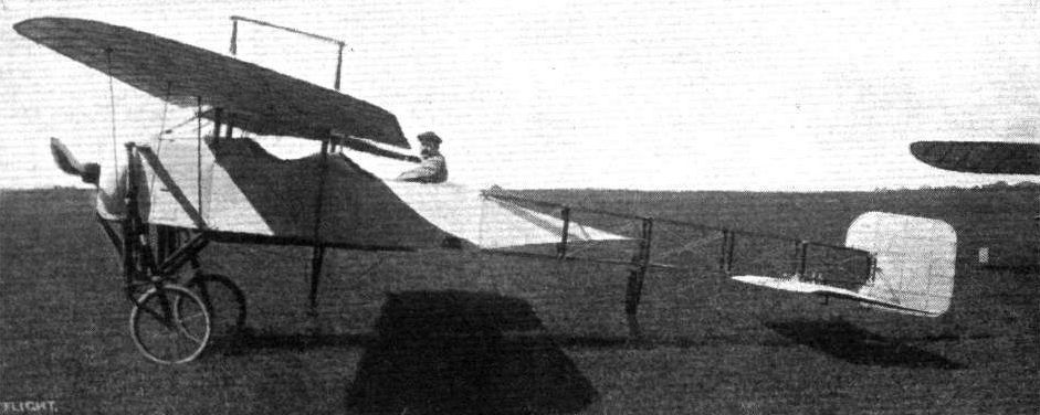
The XI-2 Vision Totale of July 1914: the Xl-2 Tandem was modified as a parasol to take an observer.

The new 80 h.p. Bleriot single-seater.
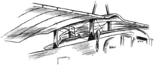
Sketch showing method of mounting the wings on the visibility type Bleriot.
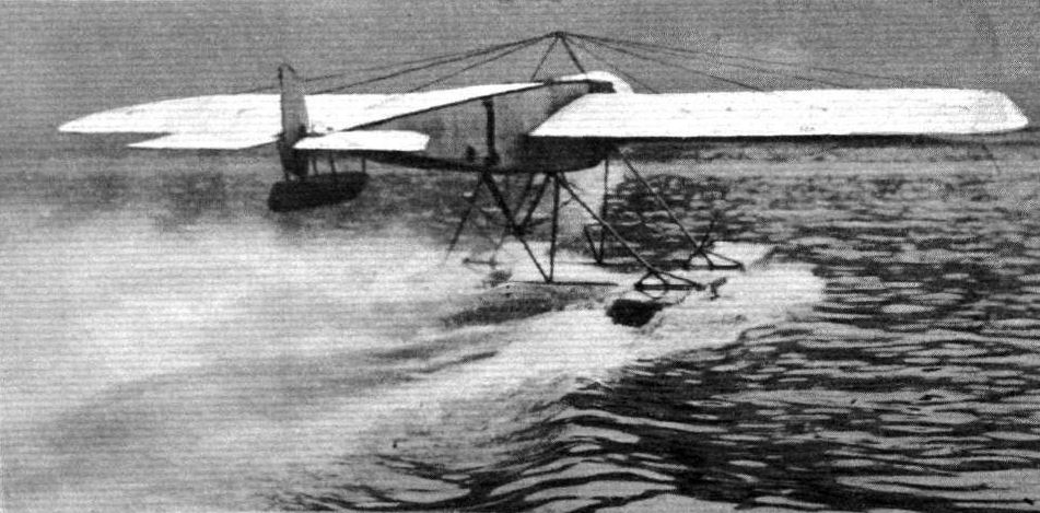
A Borel waterplane taxying, as seen from behind.
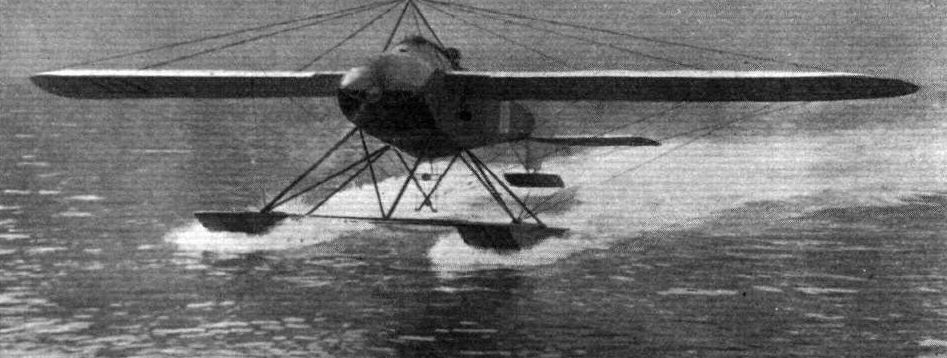
A Borel hydro-aeroplane getting under way.

Lieut. Oliver, R.P.C, N.W., arriving at Leven from Dundee on Borel 89 in dirty weather.
Flight, May 2, 1914.
AVIATION IN NEW ZEALAND.
JUDGING from some details which are to hand from Mr. J. W. H. Scotland, who has been flying a 45 h.p. Anzani-Caudron out there, New Zealand is anything but an aviator's Paradise. In spite of many difficulties, however, Scotland, on March 6th, succeeded in making a splendid flight of about a hundred miles from Timaru, South Canterbury, to Christchurch. After a preliminary flight at 6.30 a.m. at Timaru, Scotland effected a few adjustments and got away on his journey at half-past eight, the machine quickly rising to a height of 2,500 feet. When passing over Temuka a parcel was delivered by being dropped from the aeroplane, and then, as the conditions were very bumpy, the machine was elevated to 5,000 ft. There was no improvement, however, and Scotland decided to come down at Orari, where several adjustments were made to the machine, and it was not until 3.20 that the re-start was made. Then owing to the gusty wind Scotland went up to 6,000 ft. Finding no improvement he came down to an altitude of about a thousand feet, where the atmosphere was calmest, he reached Christchurch at 5 o'clock, and after circling round the town made a fine landing at Addington. During the journey both the Caudron biplane and the Anzani engine performed splendidly in spite of having to fight their way through most trying conditions. Interviewed after the flight, Mr. Scotland said that if he had not been mounted on such an excellent combination, he would have come to grief several times, as the wind from the hills seemed to form funnels and whirlpools which tossed the little Caudron about like a cork on the sea. On March 21st Scotland was at Wellington, and arranged to give an exhibition at the Athletic Park. The weather, however, was too bad, and the crowd which assembled were given tickets for the following Tuesday. On Sunday and Monday the weather was comparatively calm, but in view of the arrangement made with the ticket holders Scotland was asked not to go up. On Tuesday the weather was bad again, and it was decided to postpone the flying until the following afternoon. Then there was an improvement, although the wind was still very gusty. At half-past three Scotland decided to make a start, and after running for a short distance across the ground, the machine rose into the air. The ground was very restricted, however, and it was necessary to turn, and then it was that the utter unsuitability of the ground as an aerodrome was seen. The wind from the surrounding hills, which was broken into descending currents, eddies and puffs, made it practically impossible for any progress to be made. Realising that it was impossible to go on, Scotland very pluckily, by a great deal of exertion, got the machine over Newton Park, and eventually landed between the branches of two pine trees, the machine being suspended about 20 ft. from the ground. The nacelle and engine were practically undamaged, but, of course, the ends of the planes were crumpled up. Scotland himself climbed down one of the trees, and barring one or two rather severe cuts and bruises, was not very much the worse for his adventure. It was an unfortunate end to what promised to be a most successful tour of the country, and it is to be hoped that some patriotic New Zealanders will come forward with financial assistance to enable Scotland to continue his very useful work for the cause of aviation in New Zealand.
In the meantime, Mr. A. W. Schaef, who, as our readers will remember, has built a monoplane, fitted with a 35 h.p. Y Anzani, which was illustrated in these pages some months ago, has made one or two short flights at Lyall Bay and at Newton Park, Wellington, New Zealand. On March 16th, three flights of about 100 yards each at a height of 20 ft. were made over the beach at Lyall Bay, but unfortunately in landing on the last one a part of the chassis gave way with the result that the wings and propeller were damaged. Mr. Schaef, who, it will be recalled, is the representative of General Aviation Contractors, Ltd., in New Zealand, immediately set to work to get the machine repaired, and hopes that it will not be long now before he is able to make some really long flights.
Flight, May 22, 1914.
THE AERIAL DERBY.
THE PILOTS AND HOW TO RECOGNISE THE MACHINES.
No. 1. The 35 h .p. Caudron Biplane.
This machine is of the tractor type, but may be easily identified by the very short nacelle and by the tail booms, of which the lower ones are continued forward to form the skids.
THE MACHINES AND HOW TO RECOGNISE THEM.
No. 1. The 35 h.p. Caudron Biplane. - This machine is a standard type Caudron biplane, already familiar to our readers through descriptions in FLIGHT. The only alteration is that a different type nacelle has been fitted in order to accommodate the 35 h.p. Statax engine. Great interest will attach to the performance of this machine, since it is the first public appearance of the Statax engine. It will be remembered that a small engine of this type was exhibited at the last Olympia Aero Show, when it was described in these columns.
Flight, July 24, 1914.
EDDIES.
Mr. J. J. Morgan, manager for Mr. A. W. Jones, who took a British-built Caudron biplane, 35 h.p. Anzani engine, out to Australia, where Mr. Jones has been flying it for about eighteen months, sends us the following interesting communication:-
"When being shipped from London the machine was badly smashed, and had to be practically rebuilt on arrival at Brisbane, Queensland. Since then Mr. Jones has given exhibitions at all the principal towns in Queensland, N.S.W. and South Australia. One of his best flights was made in South Australia on January 2nd of this year, when he flew over Adelaide at a height of 3,500 ft., covering about 20 miles. He is practically the pioneer of aviation in Australia, as outside of Sydney and Melbourne there had not been any flying at all. We have found great difficulty in securing grounds especially in such out-back places as Charters Towers (North Queensland) and Broken Hill (N.S.W). The temperature at the latter was 115 degrees, rather trying for an air-cooled engine. The Caudron has covered in all about 3,000 miles in Australia, and has proved itself ideal for flying, its one great drawback for exhibition work being the cost of transport; in a country like this, where you have to travel thousands of miles, it costs a small fortune in freight. The little 35 h.p. Anzani has done exceptionally well, not having given the slightest trouble till we came to Perth a week or so ago, when we were unable to get the right lubricating oil. No doubt the weight of the pilot (9 stone) has something to do with its success. Perhaps these notes and photo, may be of use to you, and I may state that I have come across your paper in all sorts of outback places in Australia. Mr. Jones is giving exhibitions in Perth and Kalgoorlie and other towns in this state."
Flight, August 21, 1914.
EDDIES.
SINCE I referred recently to the doings of Mr. A. W. Jones and his Caudron, in Australia, a further letter is to hand from his manager, Mr. John J. Morgan, which throws some sidelights upon the conditions under which exhibition is carried on down under. From the time the machine arrived in Australia it, up to July 10th, had been erected and dismantled 28 times, while it had travelled 24,200 miles by rail and 21,000 miles by boat. On June 29th, Mr. Jones made some flights at Boulder, W.A., by permission of the Colonial Secretary, and 25 per cent, of the proceeds went to enrich the "Worn-Out Miners' Fund." He flew to Boulder from Kalgoorlie racecourse, passing over the gold mines en route, and afterwards returned to Kalgoorlie. After giving exhibition flights in North Queensland Mr. Jones proposes to fit a 50 h.p. Gnome in his machine and attempt to fly from Melbourne to Sydney.
Flight, August 28, 1914.
An Australian-built Machine.
A FEW details have been sent along by the General Aviation Contractors, Ltd., regarding the work of Mr. Delfosse Badgery, who it may be recalled is agent for G.A.C. specialities, Anzani motors, Emaillite, &c. in Australia. Since returning to Australia after taking his brevet on an Anzani-Caudron at Hendon last January, Mr. Badgery has designed and built a biplane which has proved a very fine flyer. On July 19th, in one of several trials round Sutton Forest and Wollondilly, he went to a height of over 2,000 ft., climbing the first 1,000 ft. in 2 mins. 45 secs. At the first favourable opportunity Mr. Badgery intends to fly from Moss Vale to Sydney, N.S.W. The machine is fitted with a 40-45 h.p. 6-cyl. Anzani, 1914 type, a Rapid propeller, is Emaillite doped, and wherever possible the fittings are British made.
Flight, October 16, 1914.
EDDIES.
A further batch of news is to hand from Mr. Delfosse Badgery, the Australian agent for the G.A.C., dealing with his latest activities on his Australian-built Anzani-engined biplane, which was described in these pages recently. On August 12th last he made a cross-country flight from Moss Vale to Goulburn, a distance of 49 miles. At the latter place he later gave some very successful flights. The following is an extract from a letter sent by Mr. Badgery to the Delfosse Badgery Aviation Co., in which he describes his trip :-
"At 10 minutes to 7 a,m., I had the aeroplane in the straight near the house, and at 7 I gave the signal, and all hands let go. It was interesting for me, because the 'bus had her tanks brim-full. It made no difference to her marvellous lifting power, however, and two circuits of Mewbury was sufficient to give a mean altitude of 1,500 ft., which grew from there to Carrick, where I had attained 12,000 ft. to descend, as I was beginning to lose the use of my hands, owing to the intense cold.
"Not long after this the engine back-fired for some time, and the unfired gas discharging it into the exhaust pipe was fired by the other explosions entering, and this gave rise to a series of loud reports just like huge pistol shots.
"I have heard since a small boy ran into one house and said that there was a 'haroplane lettin' off' crackers coming this way.
"My entrance to the town was at 8,000 ft. - rather sorry I was to lose that other 4,000 - but I could not stand the cold.
"After leaving home behind, the smoke of the limited express was visible about at Kareela, so I steered for that part of the globe direct, where I afterwards picked up the railway line, like a pencil track in amongst a dense forest. It was then that I saw the smoke of the second express, emerging from the hills on to the plain near Carrick. The country was beautiful; Marulan was approaching me slowly on the left, and with the altimetre creeping round over the thousands a feeling of more security came over me, as I knew then that all the dangerous country was passed over.
"Goulburn itself was now very distinct; could see it well, and would have been able to tell it was a big town in a strange land, and yet I was 20 miles away.
"A huge vol plane concluded my flight."
One of the latest machines of the Caudron type to be turned out was tried last week by Mr. L. Hall, at whose works it has been built. This Anzani-engined machine leaves the ground after a very short run, and appears to possess remarkable climbing powers for a machine of only 35 h.p. It will be used as a brevet machine at the Hall school after the pupils have familiarised themselves with the handling of the older biplane of the same type which has now been in use at the school for some time.
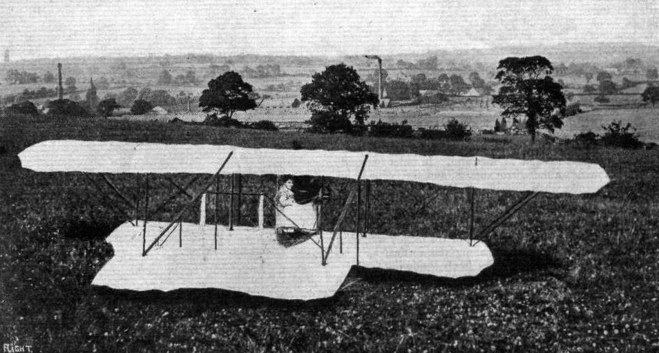
Recently Mr. Prosser had occasion to visit the Austin Motor Co.'s works at Northfield, Birmingham, when he required some work done to his engine, and he adopted the plan of making his call via the air. Our photograph shows Mr. Edwin Prosser in the pilot's seat of his biplane soon after landing in the field adjoining the Austin works, the extent of which may be gauged from the enormous range of buildings seen in the picture.

The 35 h.p. Caudron Biplane (No. 1).
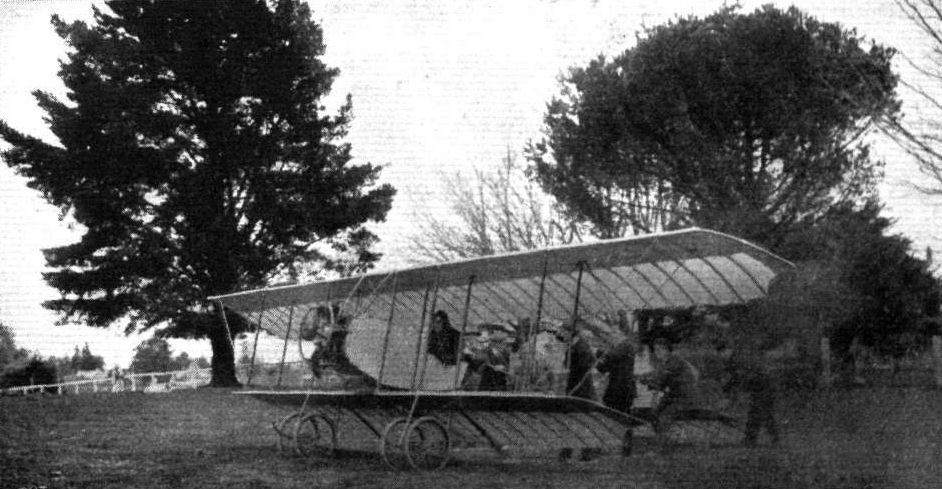
View of the biplane which Mr. Delfosse Badgery has built in Australia, and which is fitted with a 45 h.p. Anzanl motor.

Mr. A. Delfosse Badgery in the seat of his Anzani-engined biplane at Sutton Forest, New South Wales. On Sunday, July 19th, Mr. Badgery was up to over 2,000 feet, taking the air in 20 yards, and climbing the first 1,000 feet in 2 minutes 46 seconds. The distance travelled during the day was 30 miles, despite the somewhat high winds.
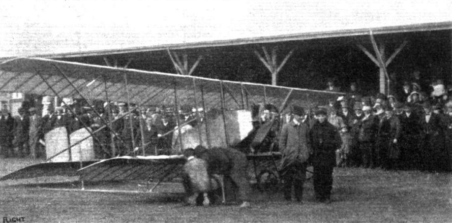
Mr. Scotland, the New Zealand aviator who has been making such good headway in introducing flying at the Antipodes, with his 45 h.p. Anzani-Caudron at Athletic Park, Wellington, on March 21st.
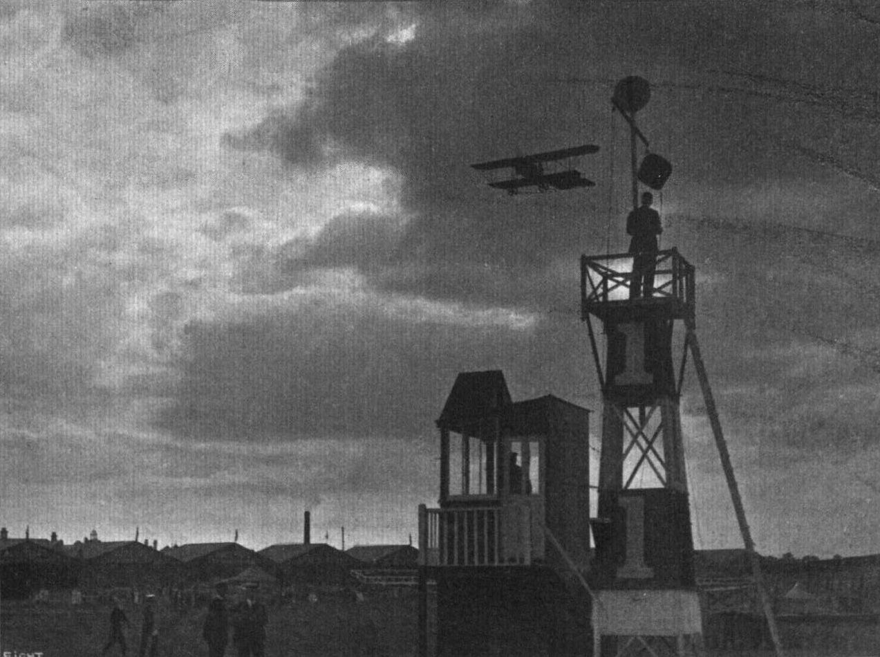
A recollection of Hendon during the past season, with Rene Desoutter negotiating No. 1 pylon on a Caudron. Very different are scenes there now under the regime of our Air Services.
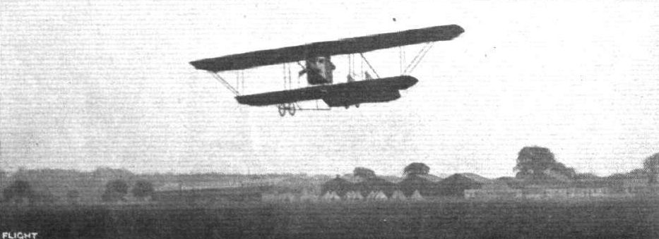
MR. L. HALL MAKING A TRIAL FLIGHT IN HIS NEW SCHOOL MACHINE. - In the background may be noted some of the tents of the R.N.R., and the big hangar which the Grahame-Whlte Aviation Co. have put up.
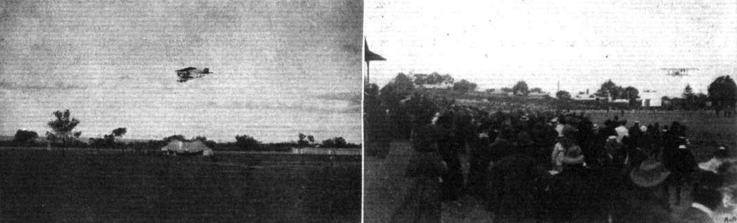
MR. A. W. JONES FLYING HIS ANZANI-CAUDRON IN AUSTRALIA. - On the left at Cheltenham Race Course, Adelaide, South Australia; on the right at Perth Oval, Western Australia.
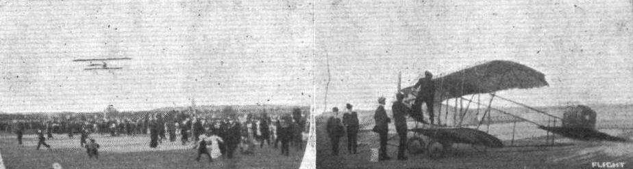
MR. A. W. JONES IN AUSTRALIA. - On the left, flying his Caudron at Kalgoorlie Race Course, June 15th; on the right at Boulder Race Course, June 29th. In both photos, the gold miner are seen in the background. In the right-hand photo. Mr. Jones is just re-filling his tanks.
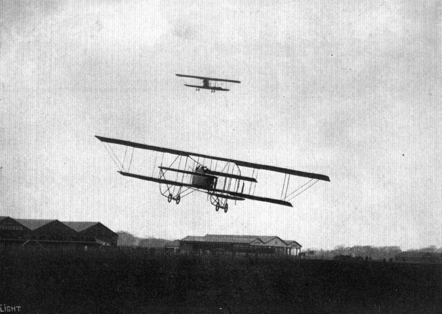
Mr. L. Noel on the Maurice Farman, flying hands off during the speed handicap on Saturday. Above is seen the Caudron piloted by Goodden.
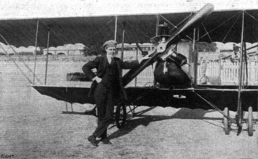
Mr. A. W. Jones and his Anzani-Caudron in South Australia.
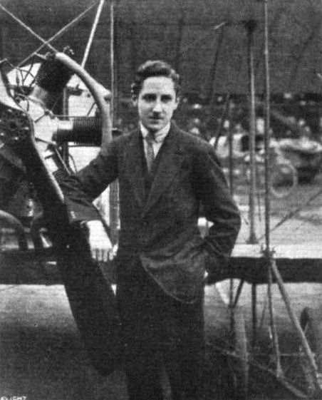
Mr. P. Legh. - One of two recent pilots who have secured their brevets on Mr. Prosser's Caudron biplane at Hendon aerodrome.
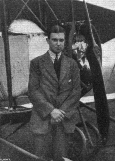
Mr. J. Rose, Instructor at the Hall School, Hendon, who recently obtained his brevet on the school 45 h.p. Caudron. His altitude in the test was 1,500 ft.
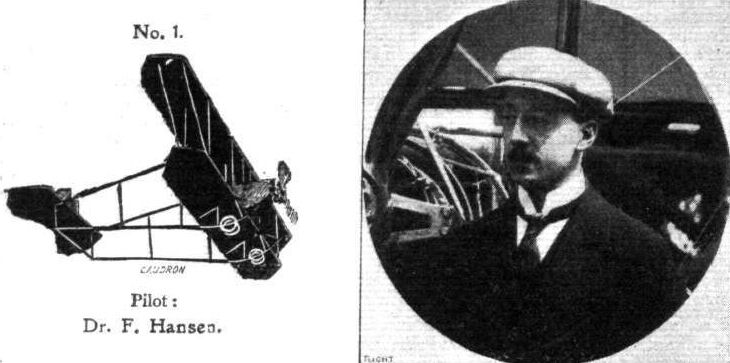
Pilot: Dr. F. Hansen.
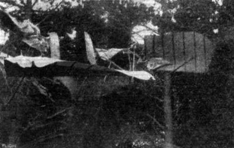
Mr. Scotland's machine in the tries after his mishap at Newton Park, N.Z. on March 24th.

Edward Baumann's "return from the stars" on his 60 h.p. Caudron biplane at Hendon Aerodrome.
Flight, May 22, 1914.
THE AERIAL DERBY.
THE PILOTS AND HOW TO RECOGNISE THE MACHINES.
No. 3. The 60 h.p. Caudron Biplane
is somewhat similar to machine No. 1, but may be identified by means of its nacelle which is differently shaped from that of the above-mentioned machine.
THE MACHINES AND HOW TO RECOGNISE THEM.
No. 3. The 60 h.p. Caudron Biplane is similar in its general arrangement to the Statax engined Caudron, with the exception that it has a standard type nacelle. The engine, a 60 h.p. Gnome, is partly enclosed in the usual way by an aluminium shield.
Flight, July 17, 1914.
EDDIES.
I HEAR very good accounts of the work done with the fleet of Caudron biplanes which were sent out to China some time ago. They are daily putting in a great amount of useful flying, and have fully justified the Chinese Government in selecting this type of machine on account of the ease with which they are mastered by pupils and their suitability for landing on the roughest ground, in addition to the other excellent qualities possessed by the products of the Caudron brothers. The accompanying photographs showing Pekin and Tientsin from above were taken by Mr. Rene Caudron, who, thanks to the stability of his mount, was able to let go of the control lever for considerable periods, in order to secure the snap-shots.
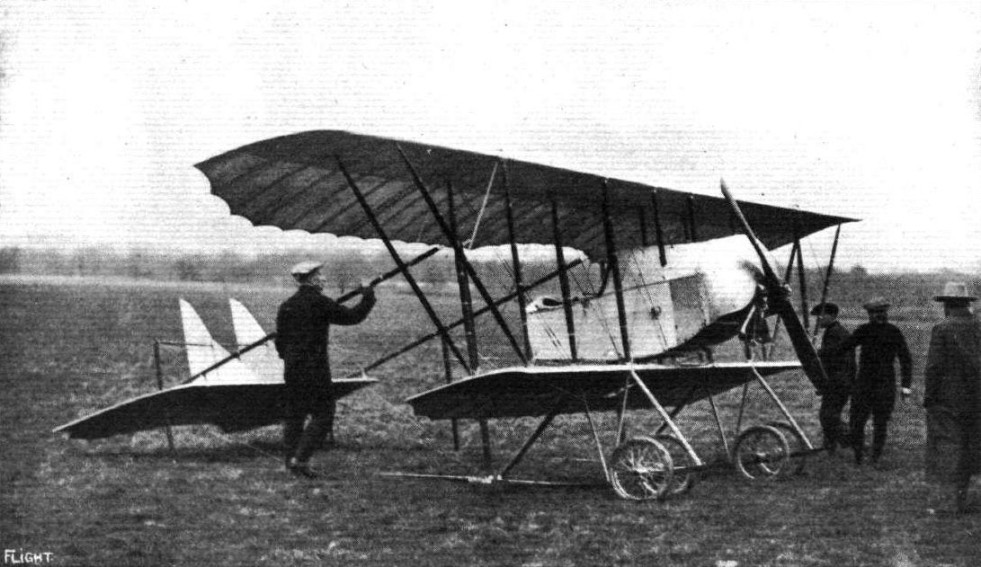
Chanteloup, the first aviator to loop the loop on a biplane in England, just about to mount his Caudron machine at Hendon on Friday last week.

Chanteloup descending on his Caudron biplane after carrying out his extraordinary loopings at Hendon on Friday.
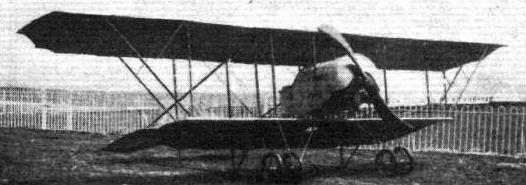
The 60 h.p Caudron biplane (No. 3).
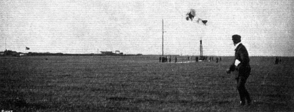
A QUICK-RISING COMPETITION AT THE RECENT VIENNA MEETING. - Our photograph shows Poulet, on an 80 h.p. Caudron biplane, winning the contest by clearing a wire 10 metres high, starting 30 metres away, giving a climbing angle of 1 in 3.
The "Temple of Heaven," Pekin, China. A photograph by Rene Caudron from a Military 80 h.p. Caudron biplane.
The French quarter of Tien-Tsin, China. A photograph taken by Rene Caudron from a Military 80 h.p. Caudron biplane.
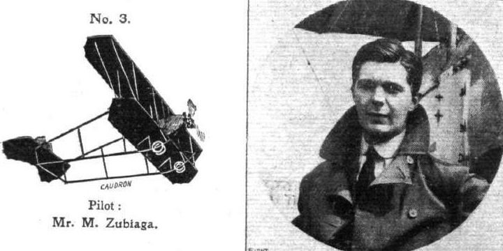
Pilot: Mr. M. Zubiaga.
THE NEW 100 H.P. 9-CYL. GNOME LAND AND WATER CAUDRON FOR THE FRENCH NAVY. - Ready for launching and getting away.

Rene Caudron in the pilot's seat of the new Caudron land and water biplane with, as passenger, the French naval pilot who will be flying this craft.

A NEW CAUDRON BIPLANE. - This machine, it will be noticed, is fitted with a fuselage similar to that of the small Caudron monoplane on which Mr. Ewen crossed the Channel in 1912. The span is comparatively short, and the usual overhang of the upper plane has been greatly reduced. Instead of the flexing tall a hinged divided elevator is fitted. The engine is a 100 h.p. Anzani.
Flight, March 14, 1914.
WHAT THERE WILL BE TO SEE AT OLYMPIA.
THE EXHIBITS.
Clement Bayard (Delacombe and Marechal). (67.)
A 100 H.P. Gnome-engined Clement Bayard armoured steel scouting monoplane will be exhibited on this stand, similar to that which was at the Paris Salon and described in our issue for December 27th last. The machine is a single-seater and a tractor, the fuselage being covered in on the underside from the engine, which is enclosed by a cowl, to the rear of the pilot, by a casing of nickel steel, for protection against rifle fire. Notwithstanding this, however, the machine is by no means as heavy as one would imagine, and it is possible that this is accounted for, in some measure, by the special system of bracing for the wings which is employed. As has been stated already, it may be said that an all-steel construction is employed, only the ribs for the supporting surfaces being made of wood. An uncovered wing will be on view at Olympia. The steel tubes for the landing chassis are of circular section, but, to reduce air resistance, they have been fitted with wooden streamlines.
In addition to the Clement dirigible engine, which is referred to elsewhere, the Avi-auto carburettor, for which special advantages are claimed, the Aerophote camera, specially designed for aerial work, the La Las Aeroplane telephone, and various forms of the C.A.D. Remote Control apparatus will be exhibited on this stand.
Flight, March 28, 1914.
THE OLYMPIA EXHIBITION.
THE EXHIBITS.
CLEMENT BAYARD (DELACOMBE AND MARECHAL).
THE armoured military single-seater scouting machine exhibited is very similar to the machine shown at the Paris Aero Salon in December last. It is built of steel practically throughout, consistent with the present practice of this famous French firm. The fuselage, which is of pentagonal shape in front running into a triangular section at the rear, is built up of steel tube longerons and struts. The rear portion of it is covered with fabric, whilst the nose and front part up to a point behind the pilot's seat is covered with an armour consisting of 3 mm. thick chrome nickel-steel plate. A cowl of the same material surrounds the engine totally, so that there should be little or no danger of this important member becoming damaged should the machine be subjected to rifle fire. The engine actually fitted in this machine is an 80 h.p. Gnome, but a 100 h.p. Gnome is the engine usually recommended for this type, which is naturally somewhat heavy on account of the armour.
The chassis, as will be seen from one of the accompanying sketches, is of a very simple type, and consists of two pairs of steel tube struts, streamlined with wood and forming a V, as seen from the side. The apexes of the two Vs are connected by two transverse steel tubes, between which move the stub axles resting in slots in the angle between the struts. Springing is provided by rubber cord.
The wings are of unusual construction in that they are built up of wooden ribs over steel spars. An uncovered wing on the stand shows the method of construction. The spars as well as the leading and trailing edges, are of thin channel steel, and very flexible, so that the amount of warp obtainable is enormous. One particular point, however, is open to criticism: there are no compression members between the spars, so that all the compression strains due to the internal cross bracing are taken by the somewhat slender ribs. However, it should be a comparatively simple matter to incorporate compression struts in the construction, and thus obviate this possibly weak point. The wing bracing is somewhat unusual in that the lower lift and warp wires are attached to the lower longeron of the fuselage instead of the chassis as it is usually done, to that should the latter give way in a heavy landing there is still a chance of keeping the wing bracing wires intact. This system also has the advantage that it practically does away with the possibility that collapse of the wings might result from going up in a machine, the chassis of which had been strained without actually breaking in a previous landing, but giving way once the machine was in the air.
The upper bracing cables are supported on a pyramidal cabane and are tightened up by means of an externally threaded tube working in the internally threaded head of the cabane. Control is by means of a single central column terminating in a fixed hand wheel which merely serves as a convenient handle. Swinging the column from side to side operates the warp, whilst a to-and-fro movement actuates the elevator. A pivoted foot-bar operates the rudder.
The tail unit consists of two members only: a balanced elevator of the divided type, having a tubular trailing edge working in a slut in the fuselage, and a balanced rudder.
In addition to the complete machine and the 850 h.p. engine described in last week's issue, there is to be seen on this stand various forms of the C.A.D. Remote Control Gear, the agency for which is held by Messrs. Delacombe and Marechal. This gear works with remarkable ease around right angle bends, and should prove particularly suitable for the various engine controls on an aeroplane.
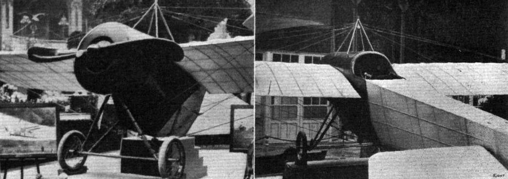
THE CLEMENT BAYARD MONOPLANE. - View of the chassis and front, and on the right a view from behind.
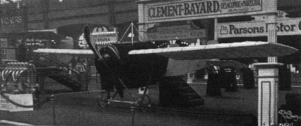
The Clement-Bayard monoplane.
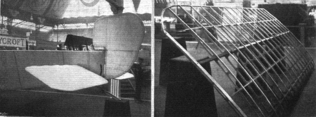
Tail planes of Ciement-Bayard monoplane, and on the right a Clement-Bayard wing with steel spars.
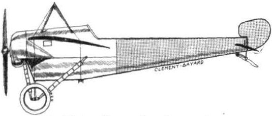
The 80 h.p. Clement Bayard monoplane.
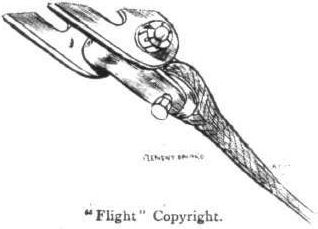
Attachment of lift cables to wing on Clement-Bayard monoplane.
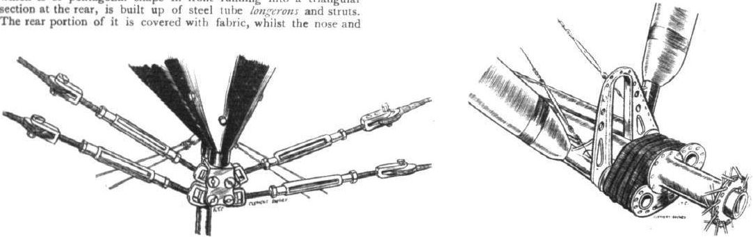
Attachment of lift cables to lower member of fuselage on Clement-Bayard monoplane, and a chassis detail.
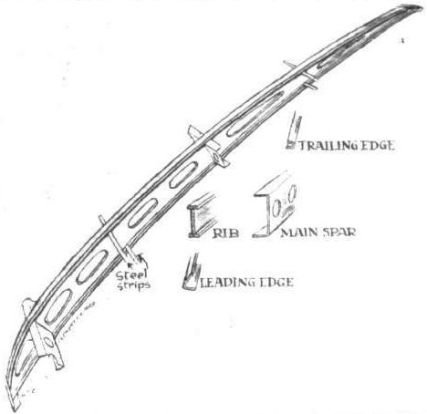
Clement-Bayard wing construction.
Flight, January 17, 1914.
THE PARIS AERO SALON - 1913.
RATMANOFF AND DE BEER.
On the Ratmanoff stand were to be seen two monoplanes, one of which was a Ratmanoff school type monoplane.
<...>
The other machine exhibited on this stand has been built by Mons. Ratmanoff to the designs of M. De Beer, and is chiefly interesting on account of the provision made for altering the angle of incidence while the machine is in flight. It is driven by an 80 h.p. Ansani engine, mounted on overhung bearings in the front portion of the fuselage. This is of rectangular section, and built up in the usual way of four longerons of ash, connected by struts and cross-members of spruce. The chassis is of a very simple type, and consists of two pairs of ash struts carrying on their lower extremities two very short skids, from which is slung by means of rubber shock absorbers the single tubular axle of the two wheels.
Inside the fuselage is the pilot's seat, from where he controls the machine by means of the control lever shown in one of the accompanying sketches. The main planes pivot round the front spar, which consists of a steel tube running right through from tip to tip, and is mounted on the fuselage. The two rear spars project slightly inside the fuselage covering, where they are secured to the system of control levers by which the angle of incidence is altered. By pulling the control lever back, the angle of incidence is increased, thus giving greater lift and causing the machine to climb, while a forward movement of the column decreases the angle of incidence, thereby causing it to descend. A side to side movement increases the angle of incidence of one wing and decreases the angle of incidence of the other, so that this operation takes the place of the warp. The elevator is connected up to the control lever, and works in conjunction with the main planes.
One point in the construction of this arrangement is open to criticism: the two rear spars are simply cut off just inside the fuselage covering, and no provision has been made for taking the compression due to the drift, which consequently has to be taken entirely by the bracing cables of the front spar. Otherwise the system appears to be quite good, although the desired object might be obtained in a somewhat simpler way.

De Beer monoplane.
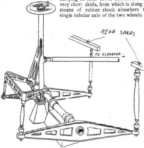
Diagrammatic sketch of the de Beer controls.
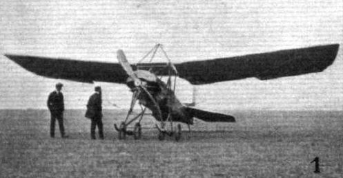
A FEW OF THE MACHINES COMPETING IN THE "CONCOURS DE LA SECURITE" EN AEROPLANE." - 1. The Deperdussin monoplane, total visibility type with automatic stability.
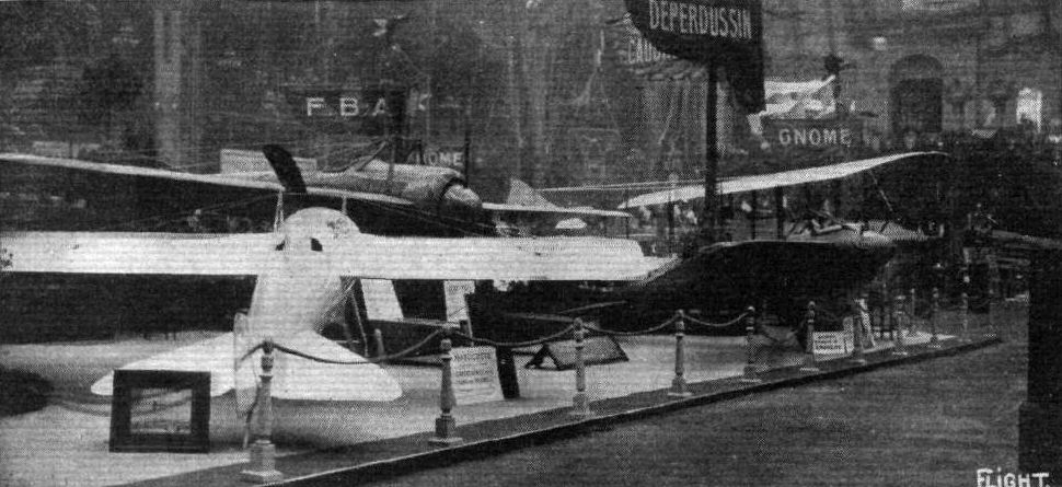
THE DEPERDUSSIN STAND. - On the left is seen the Gordon-Bennett racer, and in centre the Dep. hydro.
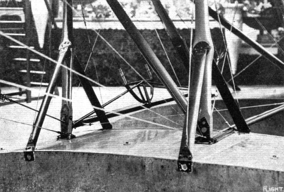
Details of the Dep. float attachment.
Flight, January 3, 1914.
THE PARIS AERO SALON - 1913.
DEPERDUSSIN.
All three of the machines exhibited on the Dep, stand had fuselages of the monocoque type, so that apparently this construction has been found satisfactory, and it certainly offers several advantages. In the first place a much better streamline may be obtained by this construction, as there are no sharp corners to cause edge disturbances. Secondly, for military purposes it would seem that this construction is less liable to get seriously damaged by bullets piercing it than would a fuselage of the ordinary girder type, for is is quite conceivable that a monocoque fuselage might be penetrated by a lot of bullets without its strength being very greatly affected, whereas a bullet hitting one of the longerons of a girder type fuselage would weaken that structure tremendously.
One of the machines shown was the actual monoplane on which Prevost won the Gordon-Bennett Race, and which was described fully in FLIGHT only a short time ago. The other land machine is the one flown by Gilbert in his famous flight from Paris to Putnitz on the Baltic Sea, a distance of 1,050 kiloms., which he covered in 5 hrs. 11 mins., or at an average speed of over 200 kiloms. an hour. The tanks necessitated by so long a flight were mounted on the outside of the fuselage in such a manner that they did not disturb the symmetry of the machine, but on the contrary were utilised to form the excellent streamline. Except for the fact that this machine has more serviceable wings braced in a more secure manner, it was practically the same as the Gordon-Bennett racer.
<...>
Flight, January 3, 1914.
THE PARIS AERO SALON - 1913.
DEPERDUSSIN.
All three of the machines exhibited on the Dep, stand had fuselages of the monocoque type, so that apparently this construction has been found satisfactory, and it certainly offers several advantages. In the first place a much better streamline may be obtained by this construction, as there are no sharp corners to cause edge disturbances. Secondly, for military purposes it would seem that this construction is less liable to get seriously damaged by bullets piercing it than would a fuselage of the ordinary girder type, for is is quite conceivable that a monocoque fuselage might be penetrated by a lot of bullets without its strength being very greatly affected, whereas a bullet hitting one of the longerons of a girder type fuselage would weaken that structure tremendously.
<...>
The third machine shown was a hydro-monoplane which does not seem to differ materially from previous Dep. hydros. It was a two-seater monoplane, with the pilot's and passenger's seats arranged tandem fashion.
Flight, February 7, 1914.
FOREIGN AVIATION NEWS.
Parmelin to Cross the Alps.
PARMELIN has arrived at Geneva with a Rhone-engined Deperdussin monocoque, with the object of making an early attempt to fly from Geneva across the Alps to Turin.
Flight, February 14, 1914.
FOREIGN AVIATION NEWS.
Parmelln Crosses Mont Blanc.
AFTER waiting at Geneva for some time, Parmelin succeeded in flying across Mont Blanc on Wednesday. Leaving Geneva at 1.39 p.m. on his Deperdussin monoplane, he made his way across the highest peak of Mont Blanc, which is 15,782 ft. above sea level, and after covering 25 miles had to land owing to the fog near Aosta, instead of continuing to Turin as intended. The greatest height attained was about 17,500 ft.
Flight, February 14, 1914.
FOREIGN AVIATION NEWS.
Parmelin at Turin.
AFTER his splendid flight across Mount Blanc, as recorded in our last issue, Parmelin intended to fly on from Aosta to Turin, but as during the next day there was no sign of the fog lifting, he decided to go on to Turin by train. He made some exhibition flights on his Deperdussin over the racecourse at Turin on Monday, Flying Across the Straits of Gibraltar.
Flight, September 18, 1914.
EDDIES.
SHOULD the story told about Lieut. Norman Spratt by the Daily Sketch be founded on fact, this well-known British pilot, who will be remembered as a very fine pilot of the Deperdussin monoplanes and Breguet biplanes, and later was entrusted with the work of testing new machines at the Royal Aircraft Factory, has distinguished himself in a highly original manner.
According to the Daily Sketch, Mr. Spratt was reconnoitering at Montmorency, and, sighting a German airman, gave chase and rose above the enemy, making him understand that he was covered by a gun. The German pilot, whose name is given as Heisden, offered (probably by means of one of those undescribable German gestures) to surrender, and planed downwards, but as he neared the ground he accelerated, and made a dash for liberty. Spratt promptly dropped on him at a height of 100 ft. The report adds that the German was taken to hospital (small wonder!), and that Spratt sustained slight injuries to his right arm.
Of course, we are all confident that the Germans will be "sat on" ultimately, and it is inspiring to know that some of them are already being so, literally. Whether the story be true or not, those of us who knew Spratt cannot help saying that it is "Just the sort of thing 'Jack' Spratt would do."
THE PARIS AERO SALON - 1913.
DEPERDUSSIN.
All three of the machines exhibited on the Dep, stand had fuselages of the monocoque type, so that apparently this construction has been found satisfactory, and it certainly offers several advantages. In the first place a much better streamline may be obtained by this construction, as there are no sharp corners to cause edge disturbances. Secondly, for military purposes it would seem that this construction is less liable to get seriously damaged by bullets piercing it than would a fuselage of the ordinary girder type, for is is quite conceivable that a monocoque fuselage might be penetrated by a lot of bullets without its strength being very greatly affected, whereas a bullet hitting one of the longerons of a girder type fuselage would weaken that structure tremendously.
One of the machines shown was the actual monoplane on which Prevost won the Gordon-Bennett Race, and which was described fully in FLIGHT only a short time ago. The other land machine is the one flown by Gilbert in his famous flight from Paris to Putnitz on the Baltic Sea, a distance of 1,050 kiloms., which he covered in 5 hrs. 11 mins., or at an average speed of over 200 kiloms. an hour. The tanks necessitated by so long a flight were mounted on the outside of the fuselage in such a manner that they did not disturb the symmetry of the machine, but on the contrary were utilised to form the excellent streamline. Except for the fact that this machine has more serviceable wings braced in a more secure manner, it was practically the same as the Gordon-Bennett racer.
<...>
Flight, January 3, 1914.
THE PARIS AERO SALON - 1913.
DEPERDUSSIN.
All three of the machines exhibited on the Dep, stand had fuselages of the monocoque type, so that apparently this construction has been found satisfactory, and it certainly offers several advantages. In the first place a much better streamline may be obtained by this construction, as there are no sharp corners to cause edge disturbances. Secondly, for military purposes it would seem that this construction is less liable to get seriously damaged by bullets piercing it than would a fuselage of the ordinary girder type, for is is quite conceivable that a monocoque fuselage might be penetrated by a lot of bullets without its strength being very greatly affected, whereas a bullet hitting one of the longerons of a girder type fuselage would weaken that structure tremendously.
<...>
The third machine shown was a hydro-monoplane which does not seem to differ materially from previous Dep. hydros. It was a two-seater monoplane, with the pilot's and passenger's seats arranged tandem fashion.
Flight, February 7, 1914.
FOREIGN AVIATION NEWS.
Parmelin to Cross the Alps.
PARMELIN has arrived at Geneva with a Rhone-engined Deperdussin monocoque, with the object of making an early attempt to fly from Geneva across the Alps to Turin.
Flight, February 14, 1914.
FOREIGN AVIATION NEWS.
Parmelln Crosses Mont Blanc.
AFTER waiting at Geneva for some time, Parmelin succeeded in flying across Mont Blanc on Wednesday. Leaving Geneva at 1.39 p.m. on his Deperdussin monoplane, he made his way across the highest peak of Mont Blanc, which is 15,782 ft. above sea level, and after covering 25 miles had to land owing to the fog near Aosta, instead of continuing to Turin as intended. The greatest height attained was about 17,500 ft.
Flight, February 14, 1914.
FOREIGN AVIATION NEWS.
Parmelin at Turin.
AFTER his splendid flight across Mount Blanc, as recorded in our last issue, Parmelin intended to fly on from Aosta to Turin, but as during the next day there was no sign of the fog lifting, he decided to go on to Turin by train. He made some exhibition flights on his Deperdussin over the racecourse at Turin on Monday, Flying Across the Straits of Gibraltar.
Flight, September 18, 1914.
EDDIES.
SHOULD the story told about Lieut. Norman Spratt by the Daily Sketch be founded on fact, this well-known British pilot, who will be remembered as a very fine pilot of the Deperdussin monoplanes and Breguet biplanes, and later was entrusted with the work of testing new machines at the Royal Aircraft Factory, has distinguished himself in a highly original manner.
According to the Daily Sketch, Mr. Spratt was reconnoitering at Montmorency, and, sighting a German airman, gave chase and rose above the enemy, making him understand that he was covered by a gun. The German pilot, whose name is given as Heisden, offered (probably by means of one of those undescribable German gestures) to surrender, and planed downwards, but as he neared the ground he accelerated, and made a dash for liberty. Spratt promptly dropped on him at a height of 100 ft. The report adds that the German was taken to hospital (small wonder!), and that Spratt sustained slight injuries to his right arm.
Of course, we are all confident that the Germans will be "sat on" ultimately, and it is inspiring to know that some of them are already being so, literally. Whether the story be true or not, those of us who knew Spratt cannot help saying that it is "Just the sort of thing 'Jack' Spratt would do."
THE DEPERDUSSIN STAND. - On the left is seen the Gordon-Bennett racer, and in centre the Dep. hydro.
PARMELIN'S FLIGHT OVER MONT BLANC. - A photograph showing a portion of this snow-dad height, over which M. Parmelin passed, a Deperdussin monoplane, on which the feat was accomplished, being seen in the photograph.
Parmelin s arrival at Aosta, after crossing Mont Blanc on his Deperdussin monoplane. A snapshot taken within three minutes of his touching earth.
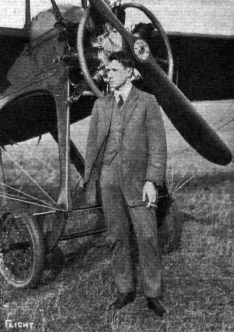
Lieut. Norman Spratt, R.F.C.

A neat way of mounting the instruments on the Deperdussin monoplane.
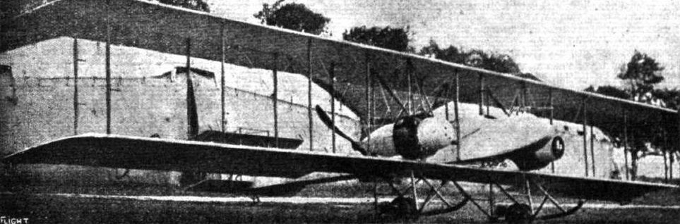
FRENCH ARMOURED BIPLANE BUILT AT CHALAIS-MEUDON. - This new product of the French military aircraft factory has a tractor type fuselage, but is a propeller biplane having two 160 h.p. Gnome engines mounted in streamline casings in the manner shown in the accompanying photograph, and each driving a separate propeller. The font portion of the fuselage is armoured with 3 mm. thick steel plates, and a Hotchkiss machine gun is mounted in the extreme nose of the fuselage, a position which provides a very wide angle of action.
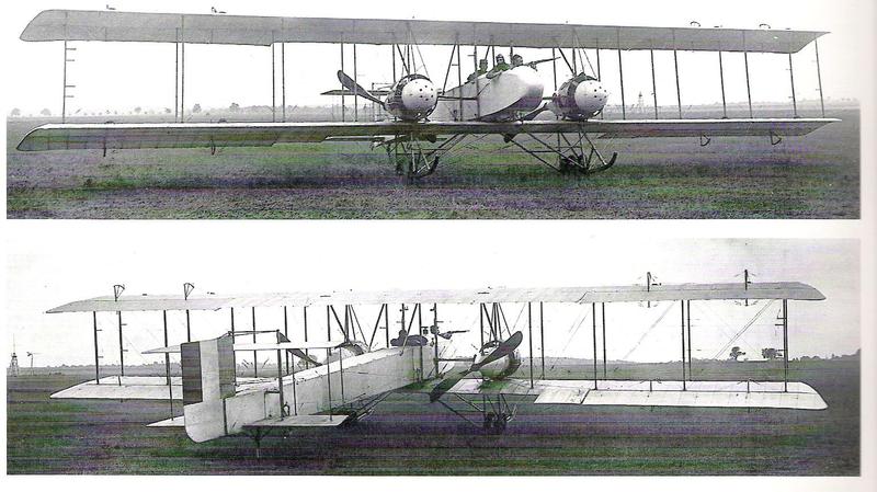
Dorand biplane armoured interceptor (80 hp le rhone engines)
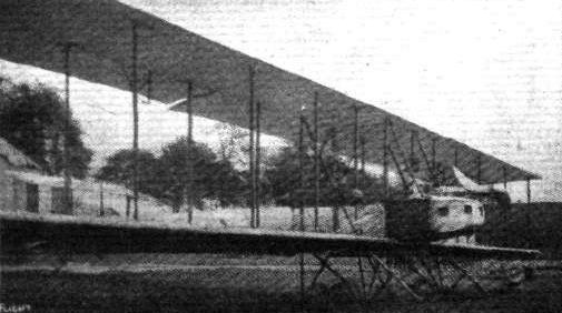
French military biplane designed and constructed at the military aircraft factory at Chalais-Meudon. - This machine is characterised by a very long and narrow fuselage, which carries at its rear end a biplane type elevator. The engine is a 200 h.p. horizontal Salmson (Canton-Unne system) driving through bevel reduction gearing a single tractor screw situated in front of the main planes and above the nose of the fuselage. Several seats are provided, and the machine is fitted with a complete set of instruments for wireless telegraphy.
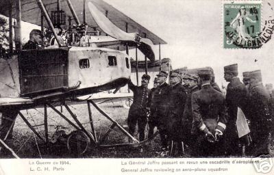
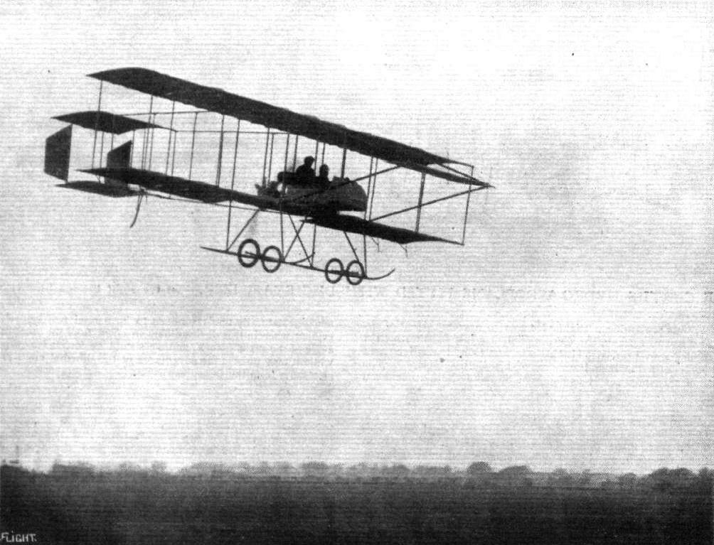
Mr. Cecil Pashley flying with a passenger at Shoreham Aerodrome.
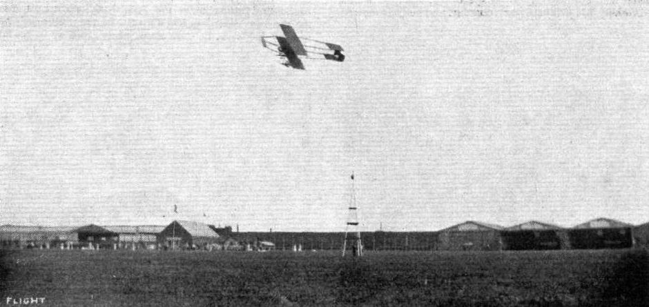
Cecil Pashley banking one of the Farmans round a pylon in last Saturday's speed race at the Shoreham Aerodrome.
Flight, March 14, 1914.
WHAT THERE WILL BE TO SEE AT OLYMPIA.
THE EXHIBITS.
Farman (The Aircraft Manufacturing- Co., Ltd.) (41.)
WILL show two machines of exceptional interest, inasmuch as neither of them have previously been shown in public in this country. One of these machines will be a H. Farman hydro., mainly interesting on account of the ingenious way in which the floats are sprung in order to minimise shock on alighting. In its general arrangement this machine will be similar to its predecessors which have already established such an excellent reputation for the Farman firm in this country and abroad, but several detail innovations will be found to have been incorporated in its construction.
<...>
Two complete nacelles, one H. Farman and one M. Farman, will complete this exhibit.
Flight, March 21, 1914.
THE OLYMPIA EXHIBITION.
THE EXHIBITS.
FARMAN (AIRCRAFT MANUFACTURING CO.), LTD. (41.)
ON this stand are shown two complete machines, one Henry Farman seaplane and a Maurice Farman land machine.
The 80 h.p. Henry Farman Seaplane follows general Henry Farman practice as regards its wings, nacelle and tail-planes, but in the chassis and float attachments numerous improvements have been effected. The main floats, of which there are two, are of the plain non-stepped type, and are sprung by rubber shock absorbers in the manner shown by the accompanying sketches. Each float is allowed to move up or down independently of the other, and also to rock slightly round its longitudinal axis, thus providing great flexibility, and minimising very considerably the shock of alighting. A single tail float of the same type as the main floats supports the tail planes when the machine is at rest.
An inspection of the interior of the nacelle reveals a lot of interesting instruments not usually fitted on the land machines, such as a wireless installation (Rouzet system). This apparatus when demonstrated never fails to attract a crowd of interested onlookers. The engine, an 80 h. p. Gnome, can be started from the passenger's seat by means of a starting handle passing through the petrol tank.
The pilot's and passenger's seats are arranged tandem fashion, and are mounted on a very roomy tool-box. The passenger occupies the rear seat, on which is mounted the transmitting key of the wireless apparatus. The rest of the machine, as has been already said, follows standard practice, and is so well known that a detailed description of it is unnecessary.
<...>
In addition to the two complete machines just described, there are shown on this stand two nacelles, one Henry and one Maurice Farman, and various excellent examples of acetylene weilding, sockets, finished parts, and model patterns of tanks, which, like the complete machines, bear evidence of the high-class workmanship which has established such an enviable reputation for this firm. Quite an interesting item in the exhibits on this stand is one of the original Fabre floats used on the first hydroplane to fly over water on March 28th, 1910. It will be remembered that the Aircraft Manufacturing Co. are sole agents for these floats.
Flight, May 2, 1914.
THE HENRY FARMAN SEAPLANE,
OF the difficulties which confront the designer of waterplanes none is perhaps greater than that of making adequate provision for the absorption of shocks due to alighting on the surface of the water. A study of some of the most successful waterplanes appears to indicate that the systems employed by designers fall into three categories. One type is characterized by flat-bottomed floats flexibly suspended from the chassis, another has rigidly mounted floats with either "V" shaped or rounded bottoms, which serve to lessen the shock when alighting, since they allow the float to sink partly into the water, thus gradually taking the load as the amount of displacement is increased, while the third type is in reality a combination of the other two, having floats with rounded or "V" shaped bottoms flexibly mounted. It will be readily seen that in the third type a form of progressive springing may be obtained by suitably proportioning the shape of the float bottom and the flexibility of the shock absorbers. It is too early yet to venture an opinion as to which type will ultimately survive, but the method of springing the floats in the Henry Farman seaplane, which belongs to the first-mentioned type, is so ingenious as to entitle this machine to special attention on that account only, apart from any other merits it may possess.
The machine itself differs in detail only from the land machines of the same make, which are already familiar to our readers, such alterations as have been effected being more in the nature of detail improvements and general dimensions; as an aeroplane the machine remains unaltered. One of the characteristics of the Henry Farman biplane that has been retained in this machine is the comparatively small gap between the planes. This is all the more noticeable on account of the increased span of the upper plane, which has an even greater overhang than that of the land machines. The reason for increasing the span is no doubt that, in order to carry the extra weight of the floats, and still keep the loading reasonably low, greater area is required, and also the extra resistance on the upper plane helps to counteract the added resistance of the floats over that of the land chassis.
As in the land machines, compensated ailerons of large area are fitted to the upper plane extensions, and are operated by the usual Farman type control lever, whilst the balanced rudder is actuated by a pivoted foot bar. The pilot's and observer's seats, which are of the bucket type, and made of aluminium, are arranged tandem fashion on a long tool box. Behind the passenger's seat is a starting handle as shown in one of the accompanying sketches, and the back rest of the seat is pivoted at one end so that it may be swung upwards out of the way to provide clearance for the starting handle.
The petrol and oil tanks are mounted on transverse steel tubes resting on the upper longerons of the nacelle, thus ensuring a free flow of petrol from the tank to the carburetor in all ordinary positions of the machine. An interesting point in connection with the construction of the nacelle is the employment of steel-tube longerons in the front portion. This method of construction has the advantage, amongst others, that there is no wood to splinter and injure the pilot in case of a smash. In the rear portion of the nacelle, where they serve as supports for the engine bearers, the longerons are of wood, thus lessening the vibration. The engine - an 80 h.p. Gnome - is mounted on overhung bearings, and sufficient clearance is provided for the propeller by cutting away part of the trailing edge of the upper plane.
The two main floats, which are of the plain non-stepped type, are supported each on two telescopic steel tubes carrying cross-pieces that serve as anchorage for the rubber shock absorbers. The telescopic tubes are provided with universal joints at both ends to allow of the free movement of the floats. From the upper cross-piece, which is welded to the lower telescopic tube, wires are taken to the gunwales of the floats. These wires have incorporated in them small coil springs enclosed in metal casings, as shown in the accompanying sketch, so that the floats are free to oscillate slightly around their longitudinal axis.
Oblique transverse tubes run from the inner gunwales of the floats to a central tubular structure coming down from the nacelle. These tubes are attached to the structure by means of a hinged joint, whilst their attachment to the floats is by means of a ball-and-socket joint in order to allow of the upward travel of the float. The object of the hinged joint at the point of attachment to the central structure is to allow the outer ends of the tubes to travel upwards with the float whilst at the same time preventing the tubes from turning broadside on.
It will thus be seen that each float is capable of three separate movements, i.e., it can move upwards and downwards bodily, it can rock slightly round its longitudinal axis, and, finally, as both front and rear chassis struts are provided with shock absorbers, the float can oscillate round its transverse axis. Under actual working conditions the movements of the floats are of course combinations of the three above-mentioned movements of which the floats are capable. The flexibility of this arrangement is enormous as each float can adapt itself independently of the other to the unevenness of a rough sea.
A small float supported on four steel tubes takes the weight of the tail planes when the machine is at rest on the surface of the sea. The workmanship in the Farman machines already enjoys such an excellent reputation that it is unnecessary to enlarge upon it here - suffice it to say that, in the machine described, the workmanship is well up to the usual high standard maintained by the Aircraft Manufacturing Co.
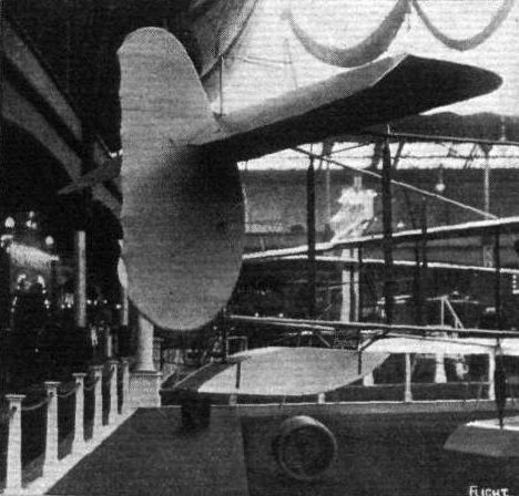
Tail planes and float of H. Farman seaplane.

Nacelle and chassis of H. Farman seaplane.

The 80 h.p. H. Farman seaplane.
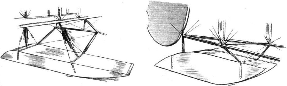
One of the main floats with its attachment on the H. Farman seaplane, and on right the tail float.
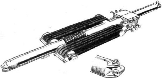
Detailed sketch showing method of springing on H. Farman seaplane.

Left, the coil springs incorporated in chassis stay wires on Henry Farman seaplane. Centre, the leaf spring skid on the heel of the main skid of the M. Farman. On right, a neat steel clip which takes the place of the usual chain link on the Farman.
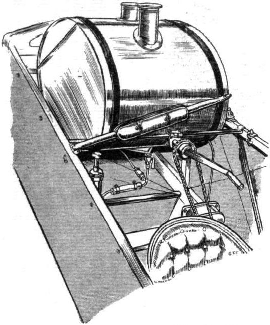
Sketch showing starting handle and petrol tank mounting on H. Farman seaplane.
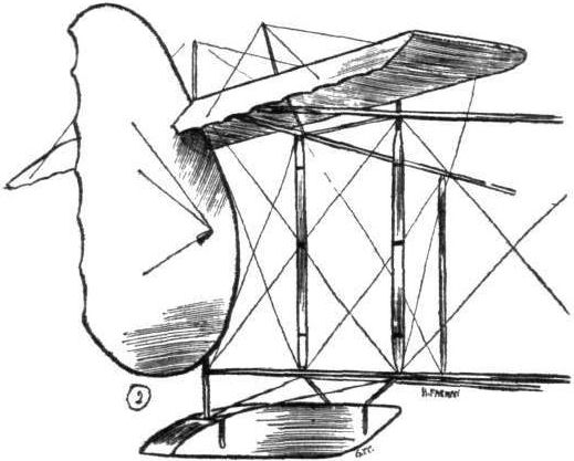
Tail planes and float of H. Farman seaplane.
H. FARMAN SEAPLANE. - Plan, side and front elevations to scale.
Flight, March 28, 1914.
BRITISH NOTES OF THE WEEK.
Biplane Looping at Eastbourne.
A SPLENDID flight was made on Monday by Mr. J. E. B. Thornely, a pupil at the Eastbourne Aviation School, who, although he passed the tests for his pilot's certificate last November, has to wait until he attains the minimum age of 18 next July before he can enjoy the privilege of holding it. On a Henry Farman biplane, built at Eastbourne and fitted with a 70 h.p. Gnome engine, he went up to a height of 3,500 ft., then dived to 2,000 ft., made a perfect loop and dived again, finishing up with a splendid landing after being in the air for twenty minutes.
Flight, May 22, 1914.
THE AERIAL DERBY.
THE PILOTS AND HOW TO RECOGNISE THE MACHINES.
No. 4. The 80 h.p. Henry Farman Biplane
will be easily recognised by the nacelle, which projects out in front of the main planes, of which the upper one has a considerable overhang. This machine is of the engine-behind type.
THE MACHINES AND HOW TO RECOGNISE THEM.
No. 4. The 80 h.p. Henry Farman Biplane is a standard type Henry Farman. It was on a similar machine that M. P. Verrier recently flew from Hendon to Monaco. The engine, as our readers are, of course, aware, is mounted in the rear of the nacelle, thus constituting this machine to be of the "pusher" type.
A B.E. and a Henry Farman flying at Upavon.

CENTRAL FLYING SCHOOL, UPAVON. - A Henry Farman in flight and some of the Maurice Farmans of B Flight on the ground.
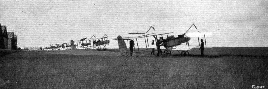
CENTRAL FLYING SCHOOL, UPAVON. - The Henry and Maurice Farmans of D Flight.
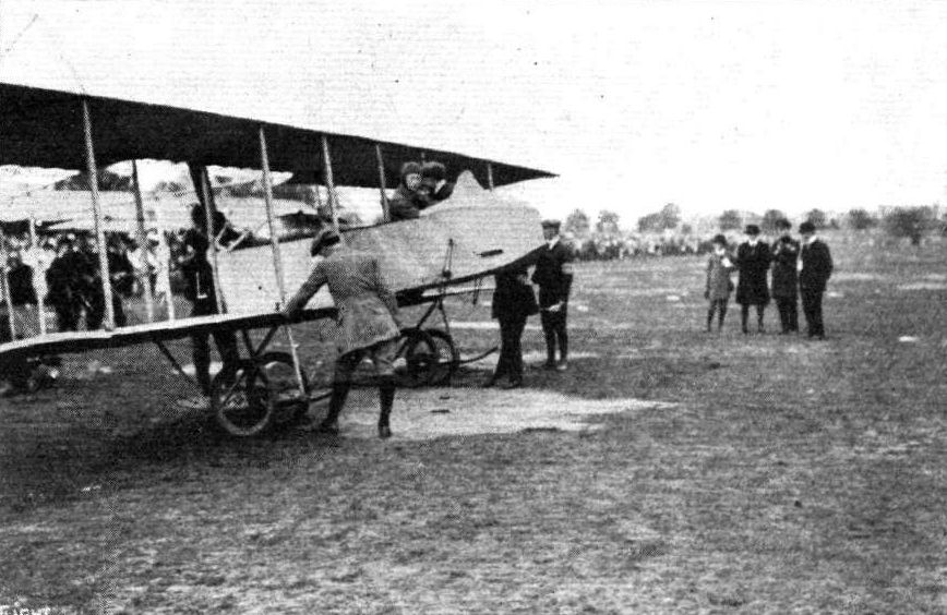
Mr. Thornely on his biplane at the Munster Aerodrome, where he has been giving looping exhibitions last week, during the time that the Prince Henry flight was in progress. Tweer was also looping on a Blerlot.

Pilot : Mr. P. Verrier.
Mr. J. E. B. Thornely, the very able seventeen-year-old pilot who last week looped the loop at Eastbourne.
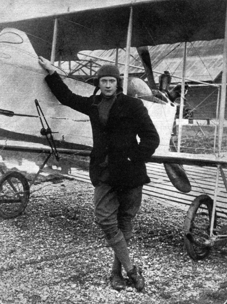
MR. J. E. B. THORNELY, who, as recorded in FLIGHT for March 28th, recently looped the loop on a Farman biplane at Eastbourne. Mr. Thornely, who will not be 18 until July 5th next, joined the Eastbourne Aviation Co.'s School in October, 1912, and last year practised on a Bleriot monoplane and later on a Bristol biplane.
Mr. J. Grant's Farman type biplane, constructed from scale drawings which have appeared in FLIGHT.
Flight, August 7, 1914.
AEROPLANE TYPES.
THE HENRY FARMAN SCOUTING BIPLANE.
SINCE the "headless" type Henry Farman biplane made its appearance in 1912, the design has not been departed from, except in detail improvements, to this day, although Henry Farman has constructed numerous experimental machines from time to time. During the last Paris Salon, however, a new type of Henry Farman made its appearance which, though departing somewhat from the usual Farman practice, still resembled the standard type in many respects. It is almost what might be called a "one-and-a-half-plane," for the lower plane is only one-third the span of the top one. The new type differs from the standard models in that the nacelle, instead of being mounted on the lower plane, is slung from the main spars of the top one, a portion of the trailing edge of which is cut away to receive the engine and propeller. In place of the usual chassis, a single running wheel is mounted at each end of the lower plane, bringing the latter very close to the ground. The upper plane extensions, each 3750 m. span, are braced by upper cabanes, and when detached can be placed on the top of the lower plane, the span of the machine then being only a little over 4 m., thus greatly facilitating road transport.
The cabanes fold inwards and lie on the top of the centre section of the top plane. Four pairs of struts separate the top and bottom planes, the two inner pairs being attached to the nacelle. The tail, which is similar to that on the standard machine, is level with the top plane, and is carried by the usual system of outriggers. The engine, a 50 h.p. Gnome, is mounted in the usual way on the rear end of the nacelle, the pilot being seated at the forward end immediately in front of the top plane, where an exceptionally good view all round can be obtained; in fact, this machine is about the best that has been yet designed so far as observation purposes are concerned.
Under the pilotage of Chevillard this new type has proved entirely satisfactory, and in all probability will be seen in this country before long. The principal dimensions are: Span, upper plane 11.500 m.; lower plane 4 m. length 8750 m.; chord 1.900 m.; gap 1.400 m.; supporting area 27 sq. m.
"VEE JAY."
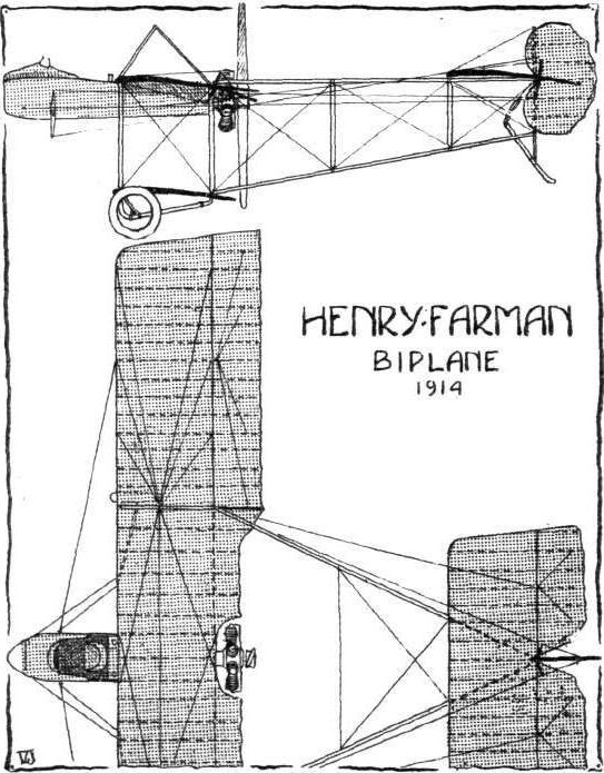
NEW H. FARMAN CHASSIS. - It will be seen that it consists of four pairs of "U" steel tubes of stream-line section, each pair of which converge at their lower extremities, where they are connected by short transverse distance pieces. It is claimed that this machine can be converted into a hydro, by simply substituting floats for the wheels. For resisting transverse strains when landing with a side wind it would seem that this chassis is an improvement on the older type H. Farman chassis.
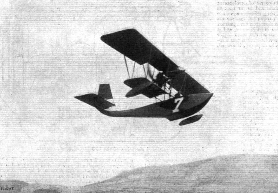
The Franco-British seaplane, piloted by Burri, the only other machine besides the winning Sopwlth seaplane to finish the course for the Schneider Cup at Monaco.
A remarkable photograph secured by Mons. E. Marchessaux at Monaco on April 20th, during the final contest for the Schneider Aviation Cup. - This negative absolutely untouched, and shows Mr. Howard Pixton's Sopwith machine passing the Franco-British seaplane piloted by M. Burri. The above is one of the autograph photographs of the amateur photographer which he presented to the two pilots who finished for this cup.
Flight, January 17, 1914.
THE PARIS AERO SALON - 1913.
GOUPY.
It was a little disappointing, especially in view of the fact that at one time these machines seemed to be full of promise and did some fine performances, to find that the Goupy firm was among the very few firms who apparently had made no progress since the previous Paris Show, when, it will be recalled, a three-seated hydro-aeroplane was exhibited.
Of the two Goupy machines on view, one was a three-seater biplane with the seats arranged one behind the other. It had the usual staggered Goupy planes, but ailerons have been fitted instead of the pivoted wing-tips formerly employed on these machines. The engine, a 9-cyl. 100 h.p. Gnome, was mounted on overhung bearings in the nose of the fuselage. The chassis, which was of the wheel and skid type, did not look any too strong for its work, and could, one would think, easily be improved.
The other machine shown was a small biplane of almost ridiculously small span. In its general appearance it was very similar to the three-seater, but it was, of course, very much smaller. It was driven by an 80 h.p. Gnome engine, mounted on similar bearings to those of the big machine, the cowl covering it being shaped to form the nose of the fuselage.
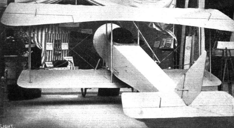
The Goupy single-seater.
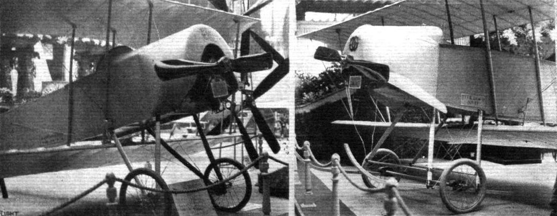
CHASSIS AND ENGINE MOUNTING OF THE GOUPY SINGLE-SEATER. - On the right the tandem-seater Goupy biplane.
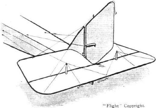
Tall planes of the Goupy biplane.

The Hanriot monoplane flying at Hendon Aerodrome on a recent Saturday.
Flight, May 22, 1914.
THE AERIAL DERBY.
THE PILOTS AND HOW TO RECOGNISE THE MACHINES.
No. 7. The 100 h.p. M. Farman Biplane.
This machine will be readily recognised, as it is the only one in the race having a front elevator.
THE MACHINES AND HOW TO RECOGNISE THEM.
No. 7. The 100 h.p. Maurice Farman Biplane is the identical machine on which Mr. Jack Alcock has been doing such a great amount of excellent flying during the past months. Instead of the 70 h.p. Renault engine usually fitted on the Maurice Farman biplane, this machine is equipped with a 100 h.p. Sunbeam engine, which of cour.se increases its speed considerably.
Flight, July 24, 1914.
EDDIES.
By flying from Brooklands to the Brighton-Shoreham aerodrome on Saturday week in order to compete in the speed event in the afternoon, Jack Alcock added a little bit more to the steadily growing tale of cross-country flying on his Maurice Farman biplane with 100 h.p. Sunbeam engine. It may not be generally realised that the mileage is now somewhere in the neighbourhood of 30,000 miles, an excellent record for pilot as well as both aeroplane and engine. The little jaunt from Brooklands to Brighton with a passenger was made in just over half an hour.
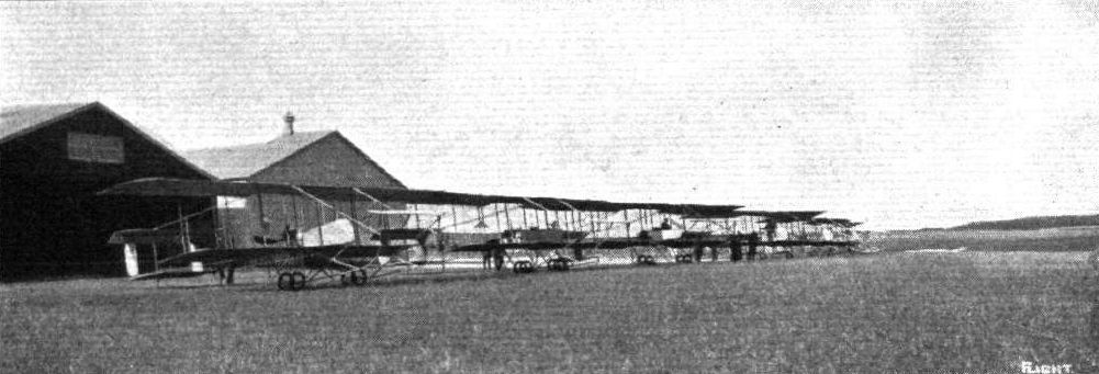
CENTRAL FLYING SCHOOL, UPAVON. - The Maurice Farmans of B Flight.
CENTRAL FLYING SCHOOL, UPAVON. - The Henry and Maurice Farmans of D Flight.
CENTRAL FLYING SCHOOL, UPAVON. - A Henry Farman in flight and some of the Maurice Farmans of B Flight on the ground.
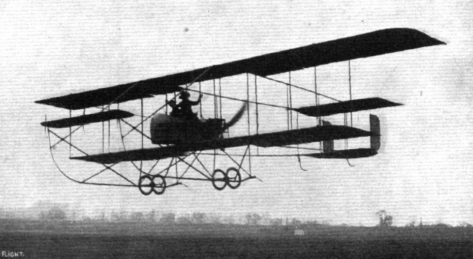
Mr. Noel, at Hendon, flying on the Maurice Farman with Miss Kitty Kent, who is so prominent in "The Girl from Utah."

AT HENDON AERODROME. - Louis Noel on the Maurice Farman rounding No.1 Pylon towards evening.

A fine bank by J. Alcock on his M. Farman biplane, 100 h.p. Sunbeam engine, at the Shoreham Aerodrome.
Mr. L. Noel on the Maurice Farman, flying hands off during the speed handicap on Saturday. Above is seen the Caudron piloted by Goodden.
CLOSE FINISHING AT HENDON DURING THE SUMMER RACING SEASON. - Mr. Lillywhite on the Grahame-White biplane and Mr. Birchenough on a Maurice Farman.
RACING AT HENDON. - The second heat of the Speed Handicap on Whit Saturday. From left to right the machines are: Messrs. R. J. Lillywhite (G.-W. twin rudder), Verrier (Maurice Farman), W. Birchenough (G.-W.-Maurice Farman), and L. Noel (Bleriot).

Byfleet, 1,000 ft. up, as seen from the 100 h.p. Sunbeam-engined Maurice Farman, piloted by Mr. J. Alcock.
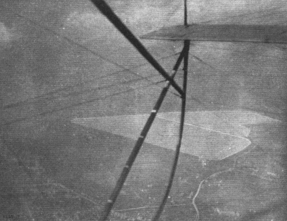
Staines Reservoir, from 4,300 ft. up, another snap taken from Mr. J. Alcock's 100 h.p. Sunbeam-engined Maurice Farman.
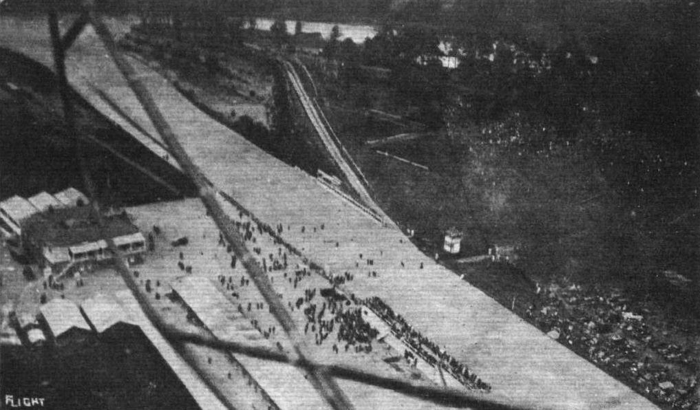
A snap of the Whitsun Motor Race Meeting at Brooklands from Mr. Jack Alcock's Sunbeam-englned biplane.
THE "CITY OF DISTANCES," AS MADRAS IS CALLED. - Photographs taken bv Mr. Wilfred R. Wills from Mr. Madeley s Maurice Farman biplane, of the residential quarter of Madras at 6.45 a.m. Each house has a large compound, and the town covers a very large area. The Ghosha people came on to their roofs in numbers to look at the aeroplane when it dropped to 300 ft. The photograph on the right was taken at 1.000 ft. On the left is seen the mouth of the Adzar river looking towards the sea. This was taken at 7.15 a.m., the best time for flying except sometimes in the evening.
MR. MADELEY'S NEW WATERWORKS SCHEME FOR MADRAS. - The filter beds and the round elevated tank can be clearly seen in these photographs, which were secured by Mr. Wilfred R. Wills from Mr. Madeley's Maurice Farman biplane. Mr. Madeley is Special Engineer to the Corporation of Madras.
Another photograph by Mr. Wilfred R. Wills from Mr. Madeley's Maurice Farman biplane, taken, like the rest of Mr. Wills' photographs, with an ordinary Kodak. The above snap was taken during a vol plane, Mr. Madeley's hangar being seen just to the left-centre of the picture. Note the crowds of natives round about it, who are a very great nuisance when landing, as they insist upon running towards the machine. The spot is the "Mount," a military station six miles from Madras, where Mr. Madeley keeps his machine.
The Sunbeam engine power plant on the Maurice-Farman at Brooklands.
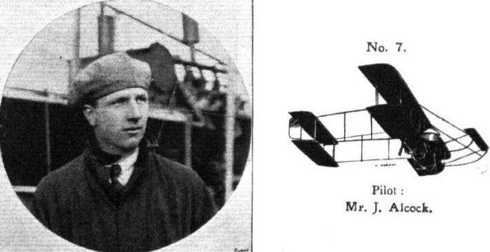
Pilot: Mr. J. Alcock.
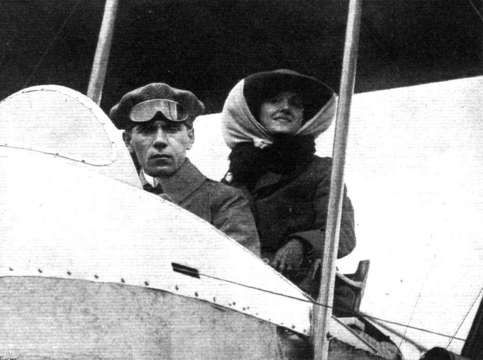
Miss Kitty Kent, who is appearing in "The Girl from Utah" at the Adelphl Theatre, is taking up flying at Hendon. Our photograph shows Mr. Noel just about to give her some practical experience in the air.
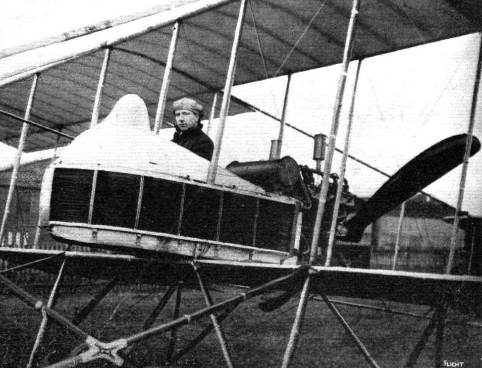
Mr. J. Alcock, on the Sunbeam-engined M. Farman, about to make a flight at Brooklands Aerodrome.
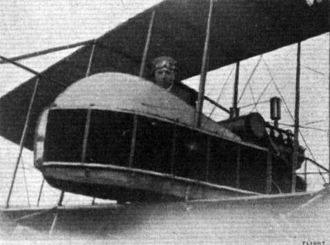
Jack Alcock in the pilot's seat of his M. Farman biplane, 100 h.p. Sunbeam engine, at the Shoreham Aerodrome.
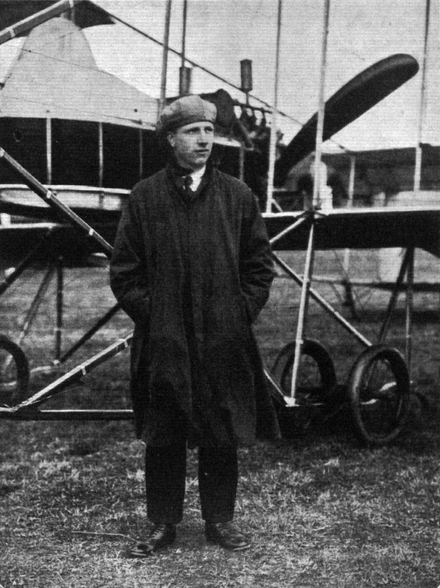
MR. J. ALCOCK, who has recently been flying the 100 h.p. Sunbeam-engined Maurice Farman so splendidly at Brooklands. Trained as an engineer, he joined Mr. Maurice Ducrocq, and was his chief mechanic for 2 1/2 years. In Nov., 1912, he took his ticket on Mr. Ducrocq's Farman, on which he won several competitions in 1913. For a short time last year he was instructor at the Avro School at Shoreham.
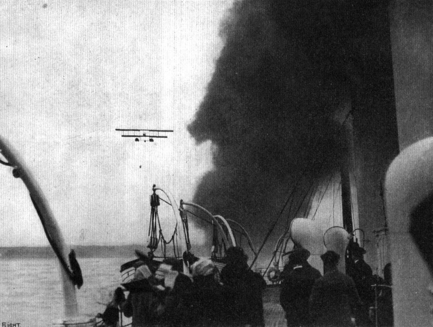
A Maurice Farman hydro-biplane piloted by Mr. Maurice Farman personally, making "rings" round the Boulogne-Folkestone boat, off the French coast.
Flight, March 14, 1914.
WHAT THERE WILL BE TO SEE AT OLYMPIA.
THE EXHIBITS.
Farman (The Aircraft Manufacturing- Co., Ltd.) (41.)
WILL show two machines of exceptional interest, inasmuch as neither of them have previously been shown in public in this country.
<...>
The second machine shown on this stand will be a M. Farman biplane of the new type without a front elevator. Several alterations from previous types of this well-known make have been effected. Most noticeable of these is, of course, the disappearance of the front elevator, which has been followed by other changes, such as raising the nacelle, so that the line of thrust now passes approximately through the centre of the gap. The tail outrigger, which is now of a slightly different form, carries at its rear extremities a tail plane of the monoplane type, surmounted by two rudders. The arrangement of the pilot's and passenger's seats, as well as of the tanks, will be found to be different from that of the usual M. Farman, whilst a close inspection of the whole machine will reveal numerous ingenious details of construction, which will be dealt with in a later detailed description.
Two complete nacelles, one H. Farman and one M. Farman, will complete this exhibit.
Flight, March 21, 1914.
THE OLYMPIA EXHIBITION.
THE EXHIBITS.
FARMAN (AIRCRAFT MANUFACTURING CO.), LTD. (41.)
ON this stand are shown two complete machines, one Henry Farman seaplane and a Maurice Farman land machine.
<...>
The 70 h.p. Maurice Farman is similar to the machine which was flown recently at Hendon, and of which we published at that time an illustration in these columns. The chief alteration in this machine is of course the disappearance of the front elevator, but several other alterations have been effected, for instance, in the tail outrigger and the tail planes themselves. In this machine the tail planes consist of a fixed tail plane of the monoplane type, to which is hinged he elevator, and which is surmounted by twin rudders. The angle of incidence of the tail plane is adjusted in an ingenious manner shown in one of the accompanying sketches, which is, we think, self-explanatory. The arrangement of the pilot's and passenger's seats is somewhat different to that of the older type, for the pilot now occupies the rear seat, from which he controls the machine by means of the usual Maurice Farman-type control. The passenger occupies the front seat, and mounted in front of him on a tripod of steel tubes resting on the upper longerons of the nacelle, is a Lewis automatic machine gun which appears to have a very wide range of action. The mica wind-shield usually fitted has been removed in order to allow of the free operation of the gear.
Other innovations are to be found in the method of mounting the petrol tank, which is now slung in steel bands resting on a transverse ash member, which is in turn supported on two A-shaped brackets on the upper longerons of the nacelle.
No oil tank is fitted, as a sufficient supply of oil is carried in the crankcase of the engine.
In addition to the two complete machines just described, there are shown on this stand two nacelles, one Henry and one Maurice Farman, and various excellent examples of acetylene weilding, sockets, finished parts, and model patterns of tanks, which, like the complete machines, bear evidence of the high-class workmanship which has established such an enviable reputation for this firm. Quite an interesting item in the exhibits on this stand is one of the original Fabre floats used on the first hydroplane to fly over water on March 28th, 1910. It will be remembered that the Aircraft Manufacturing Co. are sole agents for these floats.
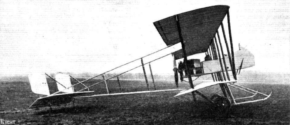
The new Maurice Farman biplane at Hendon.
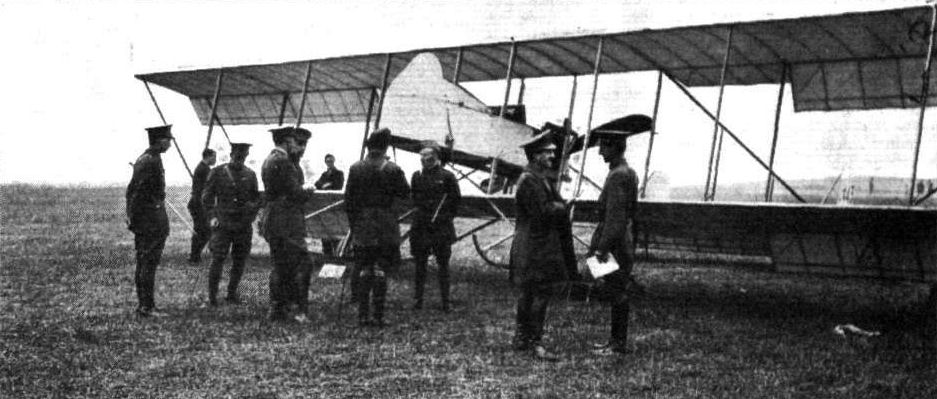
Group of officers, including Col. Sykes, Majors Brancker and Beck, and Mr. O'Brien Hubbard, in front of a Maurice Farman at Netheravon, prior to a flight.
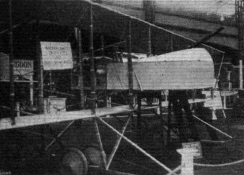
Nacelle and chassis of M. Farman biplane.
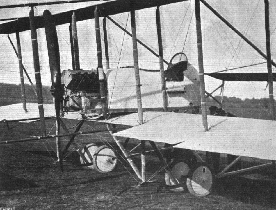
The latest M. Farman biplanes produced by the Aircraft Co. are fitted with nacelles of improved design, which add considerably to the comfort of the occupants and reduce head resistance. With this type of nacelle the machines are capable of a speed of 65 m.p.h.

Pierre Verrier on the "Shorthorn" Maurice Farman just starting at Hendon.
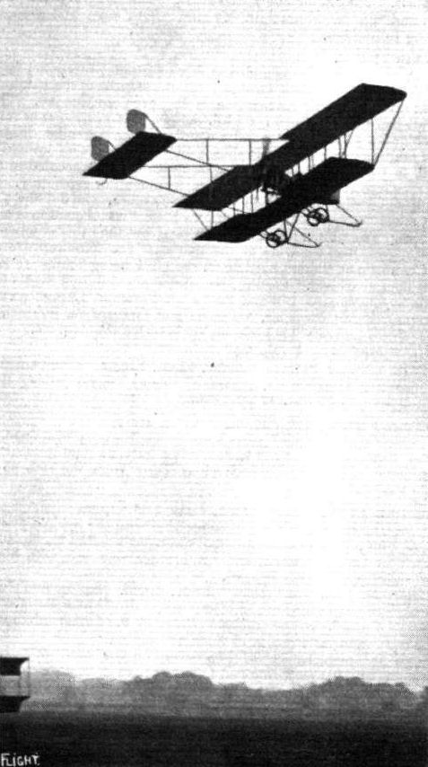
M. Verrier flying the Maurice Farman at Hendon.
FLYING AT HENDON. - Mr. Grahame-White on an M. Farman and Mr. Lillywine on the twin-rudder G.-W. 'bus over No. 1 pylon.

The 70 h.p, new M. Farman biplane.

Sketch showing method of adjusting the angle of incidence of the tail plane jon the M. Farman.
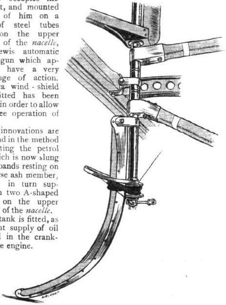
One of the tail skids of the M. Farman.
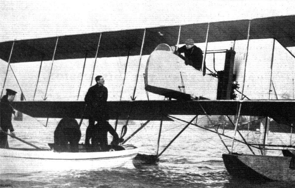
The First Lord of the Admiralty in Navy Seaplane No. 95 in Portsmouth Harbour prior to his ascent last Monday.

IN THE SMOKE OF H.M.S. "PRINCE OF WALES." - The Navy seaplane, with the First Lord of the Admiralty - Mr. Winston Churchill - on board, following the "Prince of Wales" as she is passing out of Portsmouth Harbour.
Flight, November 27, 1914.
EDDIES.
Writing from Chicago, Ill., U.S.A., Earl S. Daugherty, the American aviator, tells me that he has bought a 50 h.p. Morane-Borel monoplane on which he is doing quite a lot of flying. The machine is similar to the one flown by Vedrines in his Paris-Madrid flight, and the Gnome with which it is fitted is said to be the actual one used by Vedrines. At any rate it is numbered 75, so it can't be very new. Up to the present it has, Mr. Daugherty says, thoroughly made good.
THREE HISTORIC MACHINES IN LINE AT HELIOPOLIS. - In the centre is Marc Pourpe's 60 h.p. Gnome-Morane-Saulnier, which he flew from Cairo to Khartoum and is now flying back - this is the identical machine on which Garros crossed the Mediterranean on the left is Vedrines 80 h.p. Gnome Bleriot which was flown from Paris to Cairo; while on the right is Bonnier's 80 h.p. Gnome-Nieuport, which has also been flown from Paris to Cairo.
FLYING AT HELIOPOLIS. - The first Hangar in Egypt to fly the British flag. The machine in front is Mr. W. Oswald Watts' 60 h.p. Blerlot single-seater, and behind inside may be noticed Marc Pourpe's Khartoum 60 h.p. Morane-Saulnier on which, half an hour after the photograph was taken, he started away and flew to Suez in 1 hr. 10 mins., very fine going.
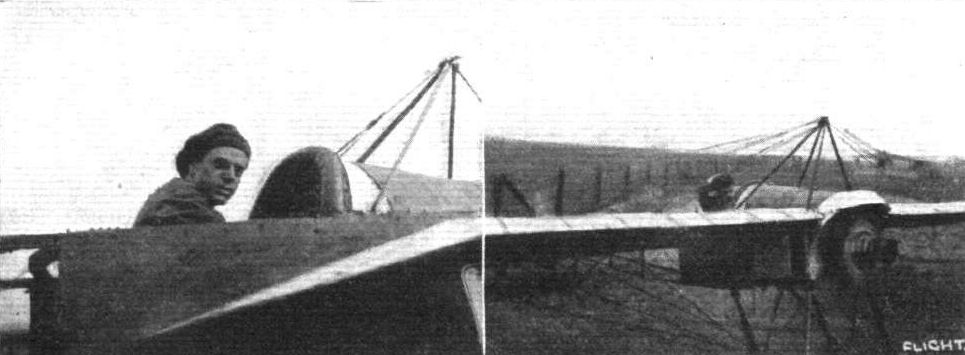
Earl S. Daugherty, the American aviator, in his Gnome-engined Morane-Borel monoplane. This machine is the fifteenth Mr. Daugherty has piloted. On the right he is seen just getting away.
Flight, February 7, 1914.
Mr. Hamel Flies Before the King.
HAVING received a command to give an exhibition before Their Majesties the King and Queen, Mr. Hamel flew from Hendon to Windsor on Thursday of last week, arriving at the Castle at about 12.45 P.m. After flying for about ten minutes over and round the Castle, Hamel alighted on the East Terrace. He was presented to Their Majesties, and the King and Queen inspected the machine. The Royal party included Princess Mary, Prince Henry and Prince John. The news of Mr. Hamel's intended visit leaked out, and a large crowd gathered within the Castle grounds and at other vantage points, Mr. Hamel had the honour of an invitation to luncheon at the Castle. At 2.30 p.m. he was again in the air giving a demonstration of high flying before Their Majesties, and hall an hour later he disappeared in the direction of Hendon; and upon this occasion Mr. Hamel did not loop the loop, but this part of the programme was carried out during another visit to Windsor on Monday. A few minutes after twelve Mr. Hamel arrived on his 80 h.p. Morane-Saulnier machine and vol planed down to the East Lawn, where Their Majesties the King and Queen, with the Princess Royal, Princess Maud and Prince John were waiting. At 12.30 p.m. Mr. Hamel ascended again, and in the course of a 17-min. flight made fourteen loops. After luncheon at the Castle Mr. Hamel gave another display of looping before returning by the air-way to Hendon.
Flight, April 18, 1914.
LOOPING THE LOOP.
A PILOT'S AND A PASSENGER'S IMPRESSIONS.
IT was just a year ago that I gave my impressions in FLIGHT of Chevillard's chute de cote. I thought it a wonderful experience then and said I would not forget it until someone took me up and flew a couple of miles upside down. I little thought at the time that it would really be possible for such a thing to happen, but aviation has made very rapid strides since then. I have not yet flown that two miles upside down, although it is now a by no means impossible proposition, but I have experienced the next thing to it - looping the loop, and I think that I must admit that the chute de cote is put in the shade somewhat by this latest method of flying. Before I received my bapteme de boucle le boucle I asked Louis Noel, who by the way, is the first pilot to loop the loop on both biplane and monoplane, to give me his impressions of looping, and I cannot do better than record them here in his own words. Thus Louis Noel:-
"In asking me for my impressions of looping the loop, I fear you have given me a difficult problem; however, I will try, but I really think there are no words in which to express the sensation. As it is, the ordinary flight is quite exhilarating, but this new stunt quite exceeds everything in the world: in fact, in a word it is superhuman. When once you have done it you feel you must repeat it again and again; you are so intoxicated with the wonderful sensation. You start off, and rise to a height of between 600 ft. and 700 ft., and then you can begin the joke absolutely without danger. After executing a gentle vol pique you pull the lever back, and the 'bus leaps with tremendous speed upwards - which it loses at the zenith of the loop. At this moment you are completely isolated from the earth and you can see nothing but the planes. Then it is that an incomprehensible sensation runs through you at being absolutely alone, suspended by an invisible string amid air. I assure you it is a unique position; nothing to fear - only happiness. All this of course (unfortunately) is done and finished in a second or so, and, after diving again, you have the first glimpse of the earth under you and you can only regret that the looping is over. There is just one thing to consider, however; I think that if I 'loop' often I shall lose that wonderful feeling."
This last statement of Mr. Noel's is, I think, rather interesting, for although, no doubt, there would always be a certain amount of exhilaration when looping, the first sensations are so strange, so unlike anything one previously imagined, yet not so very startling, and the whole proceedure is over so quickly, that once you have done it you feel that you have been doing it always, and the strangeness wears off. I asked Noel if he felt safe, and he said "absolutely," adding :-
"Many people witnessing a looping exhibition think surely the pilot is risking his life; nothing of the kind! On a suitable machine it is quite safe, and a competent pilot will find that he will accomplish his first 'loop' far more easily than his first straight flight, and I agree with Hucks that every well-trained, good pilot can do it easily.
"Again, people say that it serves no useful purpose, but I think otherwise; it is well to know how to do everything it is possible to do, and at the present stage of aviation I feel safer on a 'looping' machine than on a machine on which it is dangerous to do it."
"Well," he said," those are my impressions: but why not loop the loop yourself, and see if you agree with me?" And so, on Saturday last, I ascended with Noel on the rebuilt "G.-W." 80 h.p.. Le Rhone-Morane-Saulnier monoplane, and "saw for myself." I might mention here that Noel took out the Morane-Saulnier for the first time in his life on Good Friday, and succeeded in executing two loops with a passenger. My own impressions of looping are much the same as Noel's, but there is one point that has struck me particularly, and that is the fact that I could not realise that I was upside down. I did not feel any tendency to fall out, and if I had shut my eyes I would not have known, for the greater part of the time, that we were not flying normally. Before I ascended I took the precaution of seeing that what little coin of the realm I had in my pocket would not fall out when in an inverted position, but, as I found later, quite unnecessarily, for, once in a way, my money remained quite securely in my pocket. As far as I can put it in words, my sensations from start to finish were as follows :- After climbing to a height of about 600 ft., Noel turned and inquired if I was ready, and then we dived slightly, the feeling in this case being similar to that during a vol plane; the ground stretched out before us, then suddenly "rolled" out of sight as the nose of the machine was turned upwards, and there was nothing but the clouded sky all round. The rush of wind, which had been intense, then seemed to die out altogether for a second or so, and now one felt that wonderful feeling Noel spoke of, of being absolutely alone and extraordinarily happy. The next sensation was exceptionally weird, for suddenly there was a terrific rush of air and the earth came into view from behind and above, and passed with startling rapidity in front of the machine, just as if someone had thrown a roll of green cloth over one's head from behind so that it unrolled as it went. As the ground passed from overhead to the front of the machine, the sky again came into view overhead, coming up from behind as did the earth, and I realised then that we were diving and that we had been upside down. All this time I felt absolutely comfortable in my seat and it was only when we were recovering, our normal position that I felt any rough movement. Each time we made the loop we came out of the top of it slightly sideways, so that when the horizon line appeared above our heads it was not absolutely horizontal. As I said before, although I saw, for the space of two or three seconds, the ground stretched out above my head, I had no feeling of being upside down, owing, no doubt, to the fact that centrifugal force made my position feel quite normal. Yes! looping the loop is a really magnificent experience - but I do not propose this time to say that I will not forget it until someone takes me up in an aeroplane and does something or other remarkable, for I cannot think of anything impossible enough now for an aviator or pilot to do.
"VEE JAY."
Flight, May 2, 1914.
FLYING AT HENDON.
<...>
Glorious weather favoured the flying exhibitions on Sunday, and there was again a large attendance in all the enclosures. The following contributed to the afternoon's flying : - Claude Grahame-White, R. H. Carr, and Louis Noel made several trips on the G.-W. five-seater aerobus, three or four passengers being taken up at a time. F. W. Goodden went up on the 60 h.p. Caudron, and looped several times, and Philippe Marty also gave looping demonstrations on the 60 h.p. Morane-Saulnier, and ascended to an altitude of 7,500 ft. P. Verrier flew two new Farman biplanes, one at a time, of course - and numerous other flights were made by E. Baumann on the 40 h.p. Wright, J. L. Hall on his 50 h.p. Avro, L. A. Strange on the G.-W. tractor biplane "Lizzie," and W. Birchenough, J. M. Cripps, and R. J. Lillywhite on G.-W. 'buses. Marty's unfortunate accident occurred at about 6 o'clock. He was descending from one of his brilliant exhibitions with a rather steep dive, and when about 150 feet from the ground he started a spiral, which got sharper and sharper, until finally the machine plunged nose first to the ground, not far from No. I pylon. The machine struck the ground with such force that the fuselage telescoped, breaking in half just behind the unfortunate pilot, whilst the rest of the machine was totally wrecked. Marty was removed from the wreckage with difficulty, and though he was still alive it was seen that he was terribly injured, but fortunately unconscious. After being carried to the aerodrome hospital, where he received first aid, he was removed to the Central London Sick Asylum, and there passed away. Poor little Marty was only 21 years old, yet a magnificent and careful flyer. He was very popular everywhere in aviation circles, his unassuming, good-natured manners charming all who met him, and so he will be missed by many. How his accident originated is yet to be ascertained, but there is little doubt that had he been higher up when the machine got out of control, he would have been able to save himself.
Flight, May 9, 1914.
THE FATAL ACCIDENT TO MARTY.
IN connection with the accident which resulted in the death of Philippe Marty on Sunday week, an inquest was held at Hendon on the 29th ult.
John Stanton Chapman stated that Marty had given an exhibition of trick flying, and just before the accident he had been making some small circles with the engine off. The machine was about 100 ft. from the ground when the engine was shut off, and the machine fell head first to the ground.
Harold G. Carpenter also gave similar evidence.
Louis Noel said he tried Marty's machine earlier in the afternoon and found it all right. After the accident he examined it and ascertained that the controls were in order.
Richard T. Gates, general manager of the Grahame-White Aviation Co., said that in his last flight Marty flew several times round the course, and while doing so switched his engine on and off. That was done in order to reduce the speed of the machine - to try to fly at a slow speed. Marty was descending when he began a spiral. He did not do many circles, but those he did were very small and were not banked. Apparently Marty's intention was to go round and round and land, and when he was 40 ft. or 50 ft. from the ground the machine was perfectly straight. It seemed to bank a little, then stay motionless, then tip onus nose and dive to the ground. Witness thought that was brought about by the fact that Marty lost his speed, consequently bringing the machine round at a slow turn. If he had had another 250 ft. to drop he would probably have been able to operate his elevator successfully. Mr. Gates said he had no doubt that Marty was endeavouring to straighten the machine out as it came down, but it had not sufficient velocity to enable the elevators to act efficiently. The machine was passing too slowly through the air for the elevators to act efficiently and control the machine. Marty was an experienced aviator, and had a wonderful record for one so young. Possibly the accident was due to the fact that Marty left his motor switched off too long.
Mr. Grahame-White said that he did not see the accident, but from inquiries he had made he formed the opinion that Marty got into a steep spiral with his engine switched off, and there was a possibility that he switched on again and his motor would not go. Such a thing did happen sometimes. Failing that it might have been an error of judgment. Aviators, however skilled, did make such errors sometimes. Mr. Grahame-White said that he had just given permission to Marty to go to France for a week, and there was no necessity for him to have gone up again that evening.
The jury returned a verdict of "accidental death."
The remains of Philippe Marty were taken to France for interment on Thursday evening, and the coffin was borne to the funeral compartment in the boat express at Charing Cross by a party of men, under Superintendent Muller, from the 56th division of the St. John Ambulance Association. In the procession which followed were M. Maurice Marty (brother), Mr. H. E. Penin (secretary, Royal Aero Club), Mr. Richard T. Gates (General Manager of the London Aerodrome), Mr. B. Isaac (secretary), Messrs. Louis Noel, W. Birchenough, Beatty, Howarth, Baumann, Carr, and Strange, with about a score of mechanics also from the aerodrome. Among the many floral tributes was one in the form of a monoplane "From Hendon Aviation Pupils and the Staff of the Aerodrome."
Flight, May 22, 1914.
THE AERIAL DERBY.
THE PILOTS AND HOW TO RECOGNISE THE MACHINES.
No. 10. The 80 h.p. Morane Monoplane.
The best means for identification of this machine is its straight, angular wing tips and its landing chassis, which, as will be seen from the accompanying silhouette, has no skids.
No. 12. The 80 h.p. Morane Monoplane
is similar to machine No. 10.
No. 17. The 80 h.p. Morane Monoplane
is exactly similar to Nos. 10 and 12
No. 21. The 80 or 160 h.p. Morane Monoplane
will be similar in outward appearance to the other Moranes entered.
THE MACHINES AND HOW TO RECOGNISE THEM.
Nos. 10, 12, 17 and 21. The Morane-Saulnier Monoplanes are similar to the machines flown so successfully by Hamel, Noel and the late M. Marty, to mention just a few of the pilots who favour this machine. As scale drawings and a detailed description of the Morane-Saulnier monoplane have already appeared in the columns of FLIGHT, it is unnecessary to describe the machines in detail here. Suffice it to say that they are very fast, and as at least three of them are equipped with 80 h.p. engines, they should be particularly well matched. There is a possibility that Mr. Hamel will be using a 160 h. p. Gnome in his Morane, but failing to obtain this engine in time for the race, he will in all probability use the ordinary 80 h.p. type.
Flight, May 29, 1914.
GUSTAV HAMEL.
IT is with profound regret that we have been forced to the conclusion, as we state elsewhere, that Mr. Gustav Hamel came to an untimely end during his Channel trip which he started on Saturday morning last. Briefly the record of his movements shows that Hamel left Villacoublay at 4 40 a.m. on the new Morane monoplane with 80 h.p. Gnome monosoupape engine with which he proposed to compete in the Aerial Derby last Saturday afternoon. At 5.22 he reached Le Crotoy, and having breakfasted, he left at 8.30 for Hardelot, where he landed half an hour later. There he rested for a couple of hours, then had a light lunch, filled up the fuel and oil tanks of his machine, and left Hardelot at a quarter past 12. From that time nothing is known of the airman's movements, although the Cross-Channel steamer "Riviera" reported seeing an aeroplane flying in mid-Channel on Saturday afternoon.
Hamel was one who had done very much for the cause of aviation in this country. The son of a well-known English surgeon and a clever motor driver, it was not surprising that aviation should attract him. Having studied the question in France, he set to work and qualified for a French certificate on a Morane monoplane on February 3rd, 1911. Returning to England he repeated the necessary tests on a Bleriot monoplane, and obtained a British certificate on February t4th, 1911. He quickly showed that he was master of the Bleriot type of machine, and he was selected to pilot a Bleriot racing monoplane in the Gordon Bennet race at Eastchurch, in July, 1911. It will be recalled that on the morning of the event, a trial flight showed that the machine was slightly slower than some of his rivals' mounts. With the object of augmenting the speed, M. Bleriot decided to shorten the already very small wings, but, in the race, when rounding the first pylon, Hamel's machine side-slipped to the ground, no doubt owing to his taking too sharp a turn. The pilot was fortunately thrown clear and escaped with very severe concussion.
In July he took part in the Circuit of Britain, and after a good deal of engine trouble he was forced to retire at Dumfries. In the following September he took the principal part in the aerial post between Hendon and Windsor, flying in spite of the high winds. In the Aerial Derby of 1912 he secured the second place, last year seeing him a very popular winner of the event, whilst he was the favourite for the race which was to have been held last Saturday, the day of his disappearance. Of his many Cross-Channel trips, one of the most outstanding was that made in the course of his flight from Dover to Cologne on the Bleriot machine which was subsequently presented to the New Zealand Government.
In a match against Hucks over a course round Birmingham last August, Hamel secured a victory by a narrow margin. He won several races at Hendon, and his flying there and at Brooklands was always highly popular, especially since last November, when he added looping the loop on the Morane to his accomplishments, and he had the honour of twice being commanded to "loop" before the King at Windsor.
Flight, July 17, 1914.
THE LONDON-PARIS-LONDON AIR RACE.
ONCE more has Walter L. Brock "chewed" his way to victory, for the third of our big aviation events this year has fallen to this remarkable American flyer. As in the case of the Aerial Derby round London, and the London-Manchester-London races, Brock, as his fellow countrymen would put it, went straight for it and "got there" without any fuss or bother, and on each occasion he flew over the courses - which in two cases were quite unknown to him - under more or less unfavourable weather conditions with a remarkable degree of accuracy. This "hat trick" of his has, therefore, proved that he is undoubtedly a master of his art, and that his victory is not merely a question of luck alone. Credit is also due to his 80 h.p. Gnome-Morane-Saulnier and its makers, the Graharne-White Aviation Co. Although following the general design of the French machines, Brock's Morane - which, by the way, has done over 1,000 miles without any extensive repairs, possesses several modifications, mostly as regards dimensions Brock's win is also remarkable in that out of the six actual starters he and Garros alone completed the double journey the same day. Although only these two finished - with Renaux classed third on Sunday - it was none the less an interesting race, with several exciting incidents, whilst not a single serious accident marred the proceedings. Considerable interest was attached to the race on account of the entry of seven well-known continental flyers.
The first of these to arrive over here was Eugene Renaux, who flew over from Paris on a 120 h.p. Renault-Maurice Farman ("headless" type) with a passenger on Thursday, the 9th inst. Roland Garros, one of the favourites of the race, started from Paris at 4.20 a.m. on Friday on his 80 h.p. Le Rhone-Morane Saulnier, arriving at Hendon at about 10 a.m., after having made descents, owing to engine trouble, at Calais and in Kent. Helmuth Hirth, of Albatros fame, also started off on an 80 h.p. Le Rhone-Morane-Saulnier in company with Garros, and he too had engine trouble and descended near Surbiton, arriving at Hendon in the afternoon. The machine flown by Garros differed somewhat from the other Morane-Saulniers in the race, having a slightly modified chassis and a peculiar wing section not unlike that of the Nieuport, whilst Hirth's machine was similar to the one flown over here by Brindejonc de Moulinais. P. Daucourt, flying the 80 h.p. Clement Bayard monoplane, got as far as Crotoy, but was unable to continue to London. Lenoir on the 80 h.p. Ponnier monoplane damaged his machine at Courtenay on his way to London, whilst M. A. Parmelin on the 80 h.p. Deperdussin monoplane, after departing from Villacoublay for London, fell and smashed his machine when only just outside the aerodrome, fortunately without injury to himself.
Several test and speed flights were made at Hendon on Friday last by Garros, Carbery (80 h.p. Le Rhone-Bristol scout biplane), R. H. Carr and W. L. Brock. The former's machine developing engine trouble, mechanics, superintended by M. Saulnier himself, worked on the engine up to a late hour. R. R. Skene left Brooklands for Hendon on the 120 h.p. Martinsyde, but descended at Potter's Bar owing to engine trouble. Early in the afternoon, whilst Louis Noel was looking over his machine, he discovered that the petrol tank was leaking, and the rest of the evening was spent in putting it right.
Everyone was agog early on Saturday morning, and by 5.30 a.m. a good many people were on the ground. The weather was not at all promising, and it looked as though the elements were going to be unkind for the third time. Although there was a slight breeze and the sun was making every effort to show itself, a thick mist and clouds hung around the aerodrome at a low altitude, so low, in fact, that when Garros went up for a test flight at 5.45 a.m. he disappeared among the clouds at an altitude of scarcely more than 100 ft. Shortly before 6.30 a.m. Hirth made a test flight on his Morane-Saulnier, but his engine was running so badly that on landing it was partly taken down in order to locate the trouble. As there was but little improvement in the weather, the start was postponed to 7.30, and even at this hour it was as bad as ever. Reports from Dover being favourable, however, it was decided to make a start. Skene was expected at any moment, but by now there was little hope of any of the missing continental pilots arriving. The starting times and handicaps of the remaining competitors were as follows :-
No. Pilot and Machine. Handicap. Clock Start (a.m.).
h. m. h. m.
14. T.E. Hearn, with Mrs. Hearn as passenger
(80 h.p. Bleriot monoplane) 3 18 7 30
12. E. Renaux, with Miss Unwin as passenger
(120 h.p. Maurice Farman biplane) 2 21 7 35
7. Louis Noel (80 h.p. Morane-Saulnier mono.) 1 43 7 40
6. W. L. Brock (80h.p. Morane-Saulnier mono.) 1 36 7 45
8. R. H. Carr (80 h.p. Morane-Saulnier mono.) 1 30 7 50
3. H. Hirth (80 h.p. Morane-Saulnier mono.) 1 18 (non start)
10. R. R. Skene (120 h.p. Martinsyde mono.) 0 32 (non start)
2. R. Garros (80 h.p. Morane-Saulnier mono.) 0 32 8 5
1. Lord Carbery (80 h.p. Bristol biplane) scratch 8 10
Hearn, who employed a Rubery Owen quick release, did not get more than a few hundred yards before his engine stopped, and after a short interval he made another start, but descended on completing a couple of circuits of the aerodrome, and retired from the race. Renaux and his passenger were soon lost to view in the mist, but he had not been gone very long when he was seen returning. On landing he informed us that he was unable to find his way, as he could not see the ground at all, and so he decided to return. He made a second start, however, about an hour later. Carr, Brock and Noel all got away in fine style, but Hitth still had trouble with his engine, and so retired. The next man to start, therefore, was Garros, as Skene had not turned up. Garros misunderstood the signal to start and lost a few seconds in getting away, whilst his engine still appeared to give trouble. The last to go off was Carbery on the Bristol, and he got away in a very shaky manner, the machine being heavily loaded with petrol and oil. With the exception of Renaux and Garros all the starters wore Boddy life-saving jackets, which made them look somewhat like skippers of flying life-boats.
The last of the competitors having gone, it remained but to await news of progress along the route, and in the meantime to partake of breakfast, which, thanks to the excellent catering arrangements on the ground, was an easy and pleasant matter.
By now the weather was clearing, and giving promise of a hot and sunny day. Very shortly news came to hand that Brock had passed over Epsom at 8.2 a.m. and was flying well, whilst Garros was seen circling over Epsom Downs as though he was uncertain of his direction. A little later we heard that Carr had lost his way and had descended at Kenton, near Harrow, and that Noel had come to grief at Camber, near Rye. Noel had already started on the Channel trip when the petrol pipe broke, so he immediately turned and glided back to shore, just managing to land some 300 yards from the sea. After waiting about an hour at Kenton, Carr resumed his journey and descended once more near Dymchurch, near Hythe, where he decided to abandon the race and return to Hendon, and on landing at Ashford (Kent) on the return journey he damaged the landing chassis. There were now only four in the race, and many began to doubt if any would get to Paris, let alone return to Hendon.
Renaux landed at Epsom to enquire his way, and also at Gravesend. Brock passed over Boulogne at 9.15 a.m., Garros at 9.50 a.m., and Carbery at 10.19 a.m. Brock landed at Hardelot at 9.24 a.m. to fill up with petrol, and departed 15 mins. later, arriving at Buc 11.18 a.m. Carbery was the next to reach Paris, landing at 12.4, five mins. ahead of Garros. Brock got away immediately his two hours' compulsory stop was up, but Garros lost some considerable time in starting on the return journey, as the engine had to be overhauled (a new magneto and propeller were fitted). On the return journey Brock reached Hardelot at about three o'clock, where he stayed 12 mins. in order to fill up with petrol, and passed over Folkestone at 3.45 p.m., Epsom at 4.28 p.m., arriving at Hendon at 4 h. 48 m. 6 s., his average speed for the whole journey being 71 m.p.h. Needless to say, the reception he got was tremendous, and the scene immediately after his landing was one to be remembered. Long before the machine came to rest it was surrounded by an enthusiastic crowd that overwhelmed him with greetings and questions. The machine at last came to rest close to No. 1 pylon, and Brock stood up in his seat, silent, but smiling and chewing. First he took off his "Boddy" jacket, and then felt in his pocket and produced a letter, which he delivered to someone in a casual sort of way. His next procedure was to return his small pocket camera, which together with his foot rule he always carries with him wherever he goes, to its case. He then produced a large packet of records, and another letter, which he duly handed over to an official, and then surrendered himself to those awaiting to chair him. All this time he was silent, smiling, and chewing! Brock, guess you're some marvel! Although Brock was the first home, it was still a matter of 15 minutes before he could be declared the winner of the trophy, for Garros started that much behind him, and so the Frenchman had a chance of winning if he reached Hendon within that time. However, it soon became apparent that Garros would not be able to get in soon enough, for it was announced that he had passed over Folkestone at 5.12 p.m., and so Brock was presented with the trophy by. Lady Reid, the wife of Sir George Reid, High Commissioner for Australia. Speeches were made by Claude Grahame-White, Sir George Reid, and - a very, very short one - by Brock. Grahame-White referred to the nationality of the event, a British built machine of French design piloted by an American, and said that this kind of flight would in a very short time be quite a common occurrence - lunch in Paris and back in London for tea. He also made brief reference to the all-British attempt for the Atlantic flight.
An amusing and perhaps alarming incident occurred whilst the speechmaking was in progress, for Verrier, who was "stunting" on his Maurice Farman, suddenly swooped down over the presentation group, causing several to scatter in all directions. At about 6.20 p.m. Garros was sighted approaching in the direction of the Welsh Harp, which seemed to indicate that he had not passed Harrow, so when he landed he was asked if he had, and not being sure, he started off immediately to do so, returning soon after, and crossing the line at 6 h. 28 m. 47 s., thus obtaining second place. In the meanwhile it had been announced that Carbery had left Hardelot at 4.55 p.m., and should arrive at Hendon at about seven o'clock. News also came to hand that Renaux had arrived at Paris at 2.48 p.m., having passed Folkestone at 11.8 a.m., and Boulogne at 11.39 a.m. After a stop of two hours he resumed his journey, and landed at Boulogne at 7.45 p.m., still with his passenger. For some time after the hour at which he was expected, there was no news of Carbery, and some considerable anxiety was felt as to his safety. The Admiralty was communicated with, as it was feared that he had fallen into the Channel. Shortly before nine o'clock it was ascertained that this was the case, but happily the pilot was safe and sound. It appeared that whilst crossing the Channel, engine trouble developed so the pilot made for a tramp steamer, and as he did so his engine gave out. He planed down and alighted on the water as close to the steamer as possible, and was soon picked up by the latter dry and unhurt. The machine, in a damaged condition, was also salved. Later Lord Carbery was transferred to H.M.S. "St. Vincent," where he was well looked after by the officers, and eventually landed on Folkestone Pier.
E. Renaux, with Miss Unwin as passenger, left Boulogne on Sunday at 9.30 a.m. for Hendon, via Calais, arriving at Hendon at 12.25 P.m. He was thus the third pilot to return, and was therefore allotted third prize in the handicap. Thus ended the first London-Paris-London Air Race.
Notes of the Race.
Each of the starters carried a letter from the French Ambassador in London to the British Ambassador in Paris. Brock brought back from Paris a reply which was delivered to M. Morand.
On arriving at Paris, Brock handed over a number of postcards, stamped and addressed, and asked someone to post them for him. He soon found an old friend in Sabelli, and had a chat with him over old times whilst partaking of some refreshment. Throughout the whole journey, Brock never flew higher than 2,000 ft.
At Buc aerodrome there were many well-known personages connected with aviation, amongst whom may be mentioned M. and Mme. Bleriot, MM. C. T, Weymann, P. Prier, Jules Vedrines, Molla, Deutsch de la Meurth, Farman (sen.), and Sanchez, &c.
The following is a complete time-table of the race from start to finish, whilst elsewhere will be found further particulars of the flying at Hendon on Thursday, during the race, and on the Sunday following :-
Result of First London-Paris-London Air Race.
Prizes.- Fastest Time: Trophy and L500 presented by the International Correspondence Schools.
W. L. Brock (80 h.p. Gnome-Morane-Saulnier monoplane).
Handicap.-1st, L300, presented by the Royal Aero Club; 2nd, L150; and 3rd, L50, Presented by the International Correspondence Schools.
Times of Competitors
Hendon Pass Pass Paris Paris Pass Pass Hendon
Dep. Epsom. Boulogne Arr. Dep. Folkestone Epsom. Arr.
W. L. Brock 7 45 8 2 9 15 11 18 1 18 3 45 4 28 4 48 6
R. Garros 8 5 8 27 9 50 12 10 2 35 5 12 5 55 6 33 47
J. Carbery 8 10 - 10 19 12 4 2 4+ - - -
E. Renaux 7 35* 9 15 11 9 2 49 4 49++ Sunday aft., 12 25.
*Actually started at 8.23 a.m.
+Descended in mid-Channel.
++Landed at Boulogne, 7.45 p.m.
Handicap Time. Flying Time. Average Speed,
h. m. s. h. m. s. m.p.h.
1. W. L. Brock 5 27 6 7 3 6 71.5
2. R. Garros 7 56 47 8 28 47 58.8
3. E. Renaux 24 34 0 26 55 0 -
Flying Times Between London and Paris.
London-Paris. Paris-London. Total.
h. m. s. h. m. s. h. m. s.
W. L. Brock 3 33 24 3 29 42 7 3 6
R. Garros 4 5 42 4 23 15 8 28 57
J. Carbery 3 54 0 - -
E. Renaux 7 14 50 19 40 10 -
Flight, November 13, 1914.
WIRELESS TELEGRAPHY AND AIRCRAFT.
BEARING in mind the great part which scouting by aero planes has played in the present war, and the necessity for means of communication to and from the reconnoitering machine, a description of one of the systems of wireless installations fitted to aircraft should be of interest to our readers. It may be useful, first of all, to briefly sketch the elementary principles of wireless telegraphy for the benefit of those who may be unacquainted with this important method of communication. The fundamental basis of wireless telegraphy consists of the following electric phenomenon. If an electric current flowing through a circuit consisting, say, of a coil of wire, is intermittently interrupted, or if the direction of flow of the current alternates, a varying magnetic field will be set up round the circuit which will induce secondary currents in an entirely independent circuit placed some distance away from the first or primary circuit. Thus, a telephone receiver inserted in the secondary circuit will respond to these interruptions or reversals of current in the primary circuit. The distance at which the secondary circuit can be so affected is somewhat limited, but similar forms of induction -over great distances can be caused by means of electro-magnetic waves produced by the surging backwards and forwards of an electric current in a length of wire termed an "aerial." These waves, which have the velocity of light, are known as Hertzian waves, and are employed in the Marconi system of wireless telegraphy. How these waves are brought about and caused to transmit messages, may briefly be explained with the help of the accompanying diagrams. Fig. 1 shows the simplest form of transmitting and receiving apparatus, in which A represents the aerial, a long wire carried by a mast and insulated from the earth. The lower end of the aerial is connected to one of a pair of spark balls, S, of an induction coil, I. The other spark ball is connected by a wire to the earth, E. When a primary current from the battery, B, is made to flow through the induction coil, the aerial is charged with a high tension current until the latter breaks through the air space between the spark balls, S, in the form of a spark. The aerial then discharges itself, the current oscillating backwards and forwards from the elevated aerial and the earth MM the spark gap, each oscillation diminishing in strength until they die out altogether, when the aerial is charged again as before. Each of these trains of oscillations in the aerial produces a similar train of Hertzian waves, which radiate from the aerial into space, like ripples caused by a stone dropped into water. So long as a primary current flows through the induction coil, so as to produce a regular series of sparks at the spark gap, a constant train of waves is emitted from the transmitting aerial, but any interruptions in the primary current cause similar interruptions in the waves. By inserting a Morse key, K., in the primary circuit, therefore, the waves can be broken up into long or short trains instead of continuous ones, thus producing "dash" and "dot" signals. The apparatus for receiving these signals consists of an aerial, A\ with its lower end connected to one terminal of a "detector," D, the other terminal of which is connected to the earth, B. Also connected to the terminals of the detector is a telephone receiver, R, in series with a battery, B\ the voltage of which can be varied. When the waves from the transmitting aerial strike the receiving aerial, they induce oscillations in the latter corresponding to those originating from the former. These induced oscillating currents flow from the aerial to the earth through the detector, and thereby modify the direct current flowing from the battery through the telephone receiver and the detector, in response to the "dash" and "dot" signals. Although the type of apparatus just described is not employed in modern wireless installations, owing to its limited range of action, and other disadvantages, the general principles are the same - in fact, it might be said that the modern system is only the old one elaborated. This is illustrated by Figs. 2 and 3, which show diagrammatically a modern transmitting and receiving set, in its simplest form. There are, of course, various modifications in detail in the systems now in use, such as tuning devices, wave detectors, rotary spark gaps, &c, which cannot, in the space at our disposal, be dealt with in this article, but the following system can be treated as forming the basis of modern land and air systems. Referring to the transmitting circuit, Fig. 2, instead of employing an induction coil for providing the oscillating high tension currents in the aerial, an alternating dynamo or alternator, D, generates an alternating current at a comparatively low voltage, and this current is transformed by the induction transformer, T, into a high tension oscillating current. The latter charges a parallel plate condenser, C, until a spark jumps across the air gap between the spark balls, S, and then the condenser discharges itself through a primary inductance coil, I, setting up the surging or oscillating currents which induce similar ones in the secondary inductance coil of the aerial, A, and thus produce the Hertzian waves. The "dash" and "dot" signals are produced as before by means of a Morse key, K, inserted in the alternator circuit. The receiving circuit, Fig. 3, consists of an aerial, A1, connected to the earth, E, through a primary inductance coil, J, sometimes known as a "jigger." The train of waves striking the aerial set up oscillating currents in the jigger primary coil, inducing similar ones in the jigger secondary, which is connected to the terminals of a condenser, C. Also connected to the terminals of the latter is a detector, D, in series with which is another condenser, C2, whilst the telephone receiver, R, and battery, B, are connected to the terminals of this second condenser. The detector is so adjusted that the induced oscillating currents discharged from C flow through it only in one direction, and so charge the condenser, C2, in a series of pulsations, which make themselves felt in the telephone circuit in the form of a click in the receiver for each pulsation, corresponding to the wave trains. The battery supplies a steady flow of current through the telephone receiver and detector, as in the first apparatus, via the jigger secondary.
Having thus given a crude idea as to how wireless "works," attention may be given to its application to aircraft. Several difficulties are in the way of its successful application in this direction; for instance, it is of course impossible to have any earth connections, as in the systems just described, whilst the weight, and therefore the capacity, of the installation has to be cut as low as possible - although in the case of dirigibles this is not such a vital matter. Again, the noise and vibration of the engine on an aeroplane interferes considerably with the receiving of messages. These and other difficulties, however, are gradually being overcome, but to all intents and purposes aerial wireless telegraphy is still in the experimental stage.
The transmitting and receiving systems for aircraft are much the same as those for land work just described, the main difference being in the absence of the earth connections. In place of the latter, some other conductor must be employed, and this generally takes the form of what is known as a counterpoise capacity. This either consists of a system of insulated wires run round the machine, as shown in Fig. 4, or else all the metal parts of the machine are electrically connected, and form the conductor. The aerial is suspended below the machine, and is weighted at the end in order to keep it taut and as vertical as possible. It is generally attached to a windlass so that it may be wound up out of action when necessary.
The Marconi equipment, which has proved quite successful, shown in Figs. 5 and 6, fitted to a Morane-Saulnier monoplane, is remarkable for its lightness and compact form.
The equipment is made up of three main units, Fig. 5, placed in the cockpit of the machine in front of the pilot and passenger, consisting of a high frequency alternator and rotary disc-discharger, A, a transmitting set, B, and receiving set, C. The alternator is run by a belt drive from the motor of the aeroplane, and is claimed to absorb less than two-thirds of one horse-power. It can be supported by a horizontal tube at X and with the lugs at Y, in which case the supporting pedestal shown is not required.
The total weight of the generator and spark discharger is 80 lbs. The transmitting unit is contained in a polished case of hard wood, and weighs 84 lbs., whilst the portable receiving set is exceptionally light, weighing less than 20 lbs. The complete weight of the entire three units is under 184 lbs.
Using the cabane as a mast, the aerial, C, is run in the form of a triangle around the machine, as shown. Commencing at the pilot's cockpit, it goes to the tail, from there to the right-hand wing tip, the pylon, B, the left-hand wing tip, and back to the tail, where a further length of wire trails from the tail-skid. This trailing-wire is so connected that should it become entangled with any obstacle, a slight pull is sufficient to sever it from its connection. Spare aerials are carried to replace those so lost.
A counterpoise capacity is employed in place of the "earth" connection or in place of a second aerial as sometimes used on biplanes. All parts are thoroughly insulated so as to avoid any possibility of receiving electric shocks. The transmitting key, switches for changing over from transmitting to receiving and vice versa, and all tuning adjustments are conveniently placed on the right hand side of both pilot and passenger within easy reach of both. These three units are shown in detail in Fig. 6, and most of the component parts previously mentioned in this article will be located in the Figure.
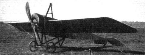
The Morane Monoplane (Nos. 10, 12, 17, 21).
Mr. Noel just "off" on his Morane at Hendon.
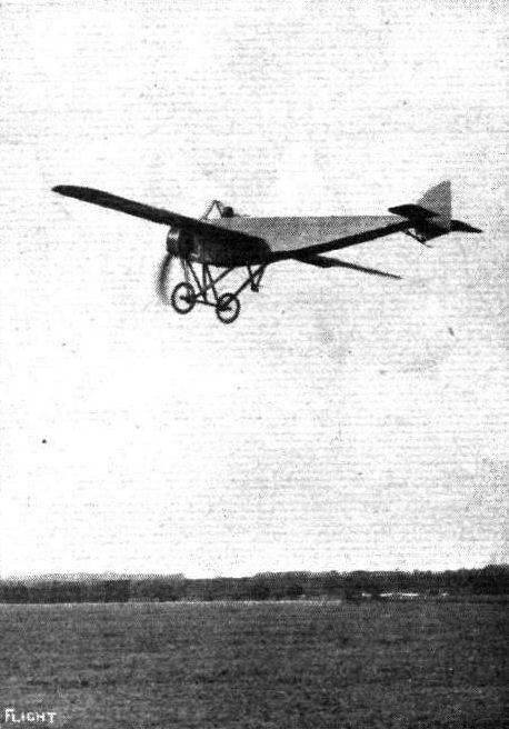
A turn round Hendon Aerodrome on the Morane-Saulnier.
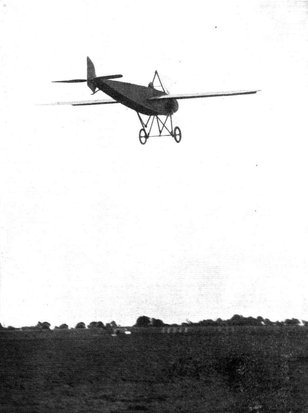
Mr. Frank Goodden flying the Morane-Saulnier at Hendon Aerodrome.
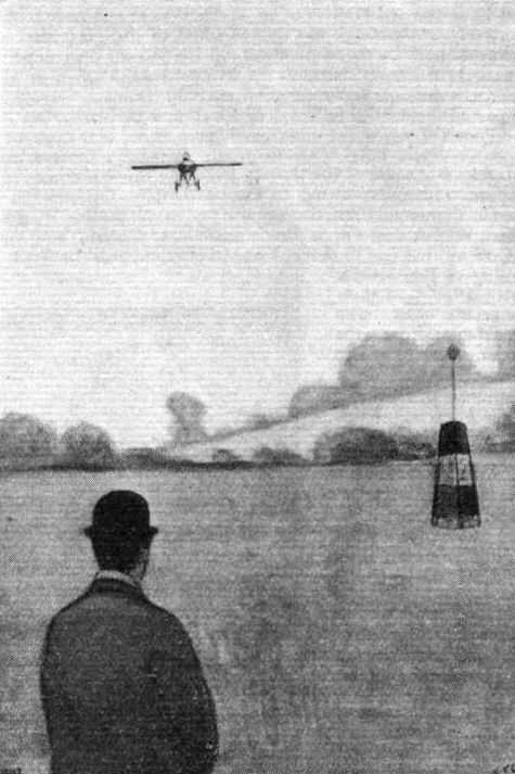
The first man to return to Hendon Aerodrome in the Aerial Derby. - Louis Noel on his Morane.

LONDON-MANCHESTER-LONDON RACE. - Finish by Brock on his Morane-Saulnier machine on Saturday last, when he won this race in magnificent time. The time estimated by the handicapper for him to arrive back at Hendon was 5.60 p.m., and within ten seconds of that time Mr. Brock passed the winning post. Note the clock in our photograph, which points exactly to the 5.50.
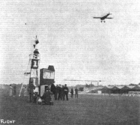
Louis Noel, on the 80 h.p. Morane-Saulnier, after having finished first in the final heat of the speed handicap at Hendon last Saturday, completing an extra lap whilst the other competitors are finishing the heat.

THE FINISH OF THE AERIAL DERBY AT HENDON. - Mr. W. L. Brock passing over the finishing line on his Morane.
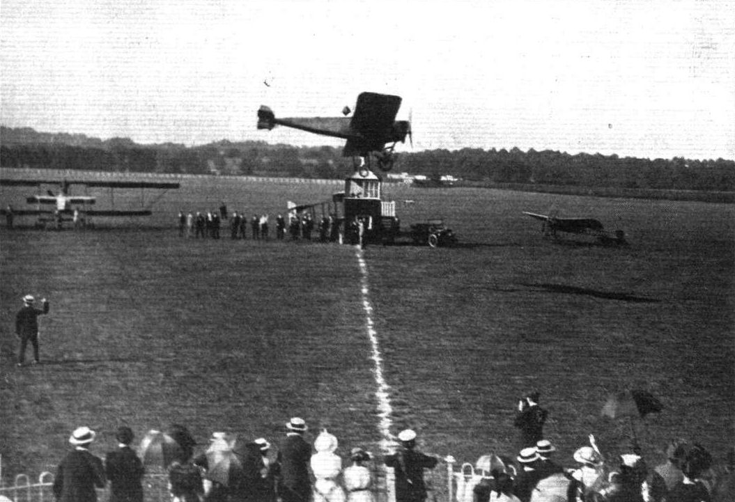
R. H. Carr winning the Cross-Country Race, with Miss Saunders as passenger, on the Morane-Saulnier mono, at Hendon on Saturday.
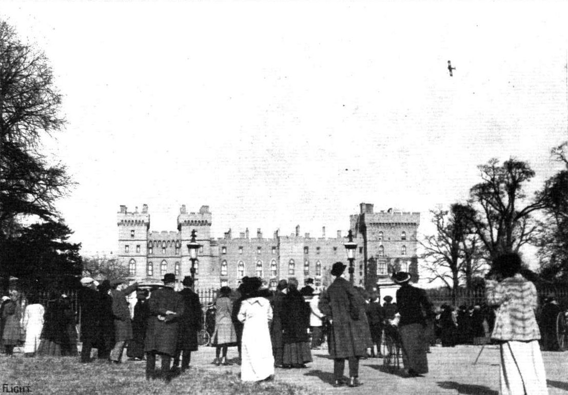
LOOPING THE LOOP BY COMMAND OF THE KING. - Mr. Gustav Hamel upside down over Windsor Castle before the King on Monday. Our photograph shows the spectators watching the evolutions from the Long Walk.
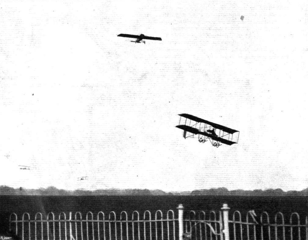
A MEMORY. - The late Mr. Philippe Marty flying in a race at Hendon.
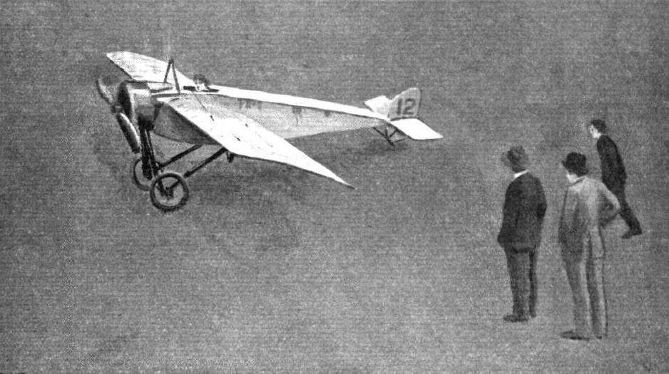
The winner of the Aerial Derby, W. L. Brock, just come to rest in the Hendon Aerodrome.
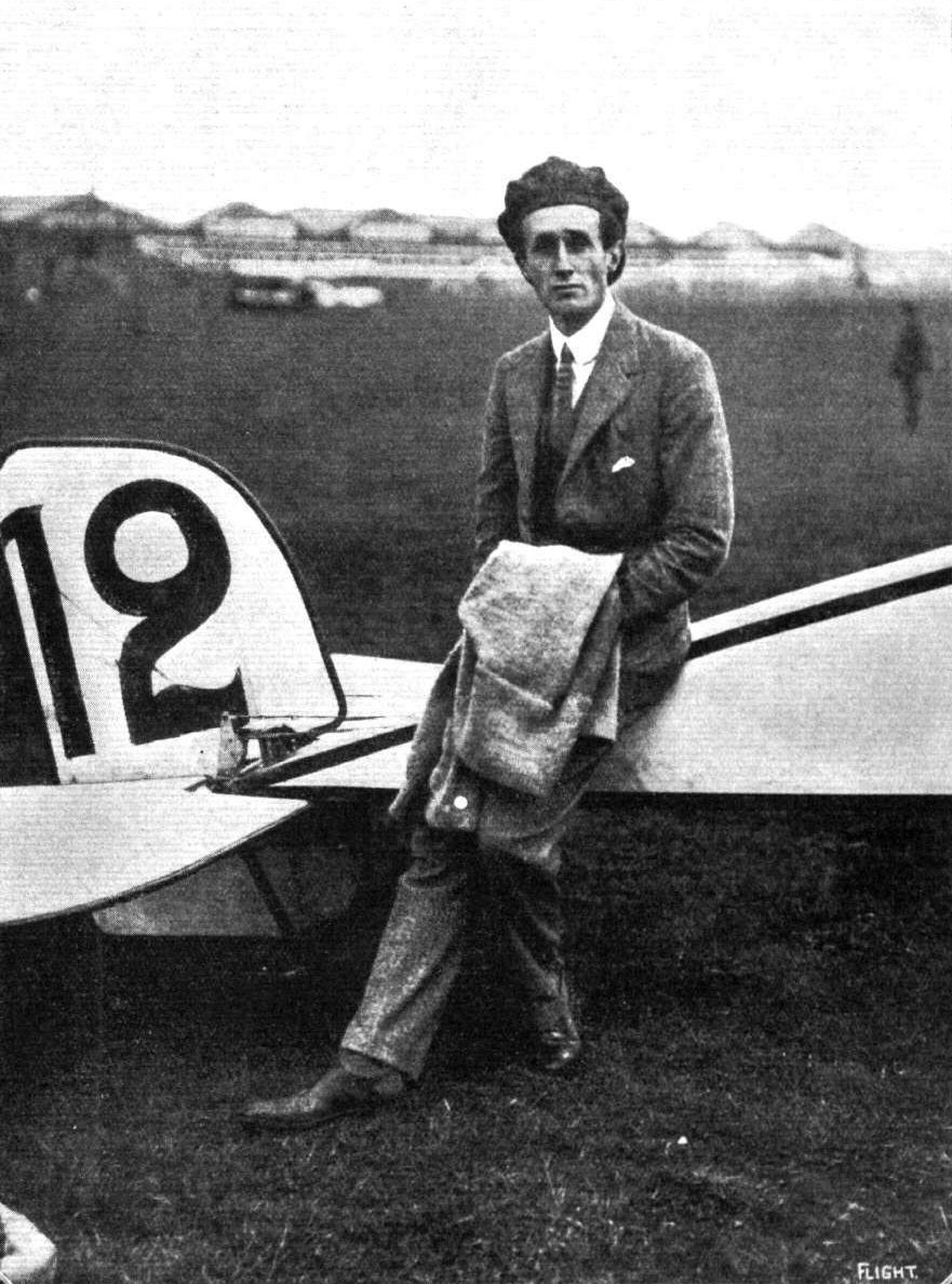
LORD CARBERY the well-known amateur who files a Morane for sport. He made a surprise flight from Paris to London in the middle of last August, soon after securing his brevet. He has entered for the Aerial Derby.
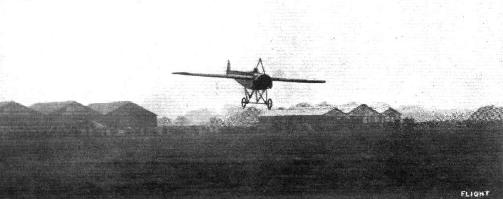
LONDON-PARIS LONDON RACE. - Brock's superb landing at Hendon on his return from Paris.

LONDON-PARIS-LONDON RACE. - Brock standing up in his machine immediately on his,return to Hendon after his splendid achievement in the Paris flight.
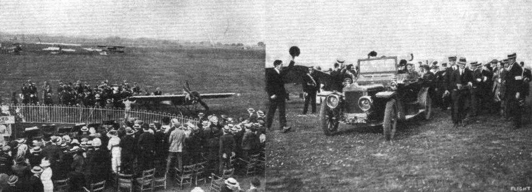
LONDON-PARIS-LONDON RACE. - Brock's reception at Hendon after winning the race. On the left, the Pilot, the Press and the People; on the right Brock being "carried" round the enclosures after his victory.
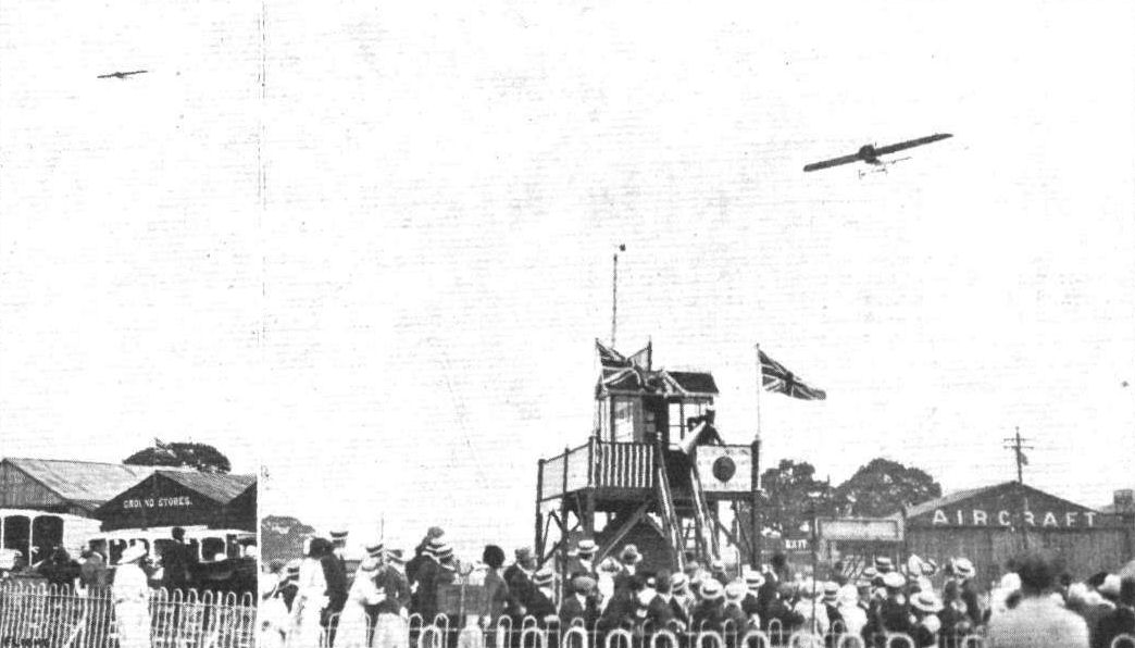
LONDON-PARIS-LONDON RACE. - Garros, the second man, arriving from Paris. On the left he is seen coming into the aerodrome on his first return, when, being informed he had missed the turning point at Harrow Church, he at once took wing again and flew back and rounded this point. On the right he is returning after this little episode, and thus formally ranking as second in.
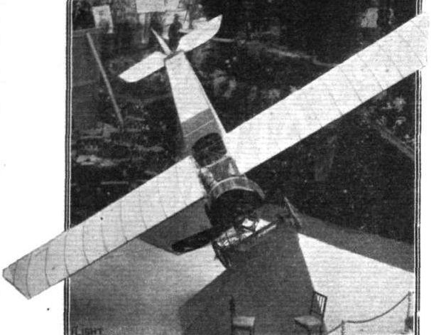
A neat way of exhibiting a machine - one of the Morane-Saulnier monoplanes.

Pilot: Mr. F. Goodden.
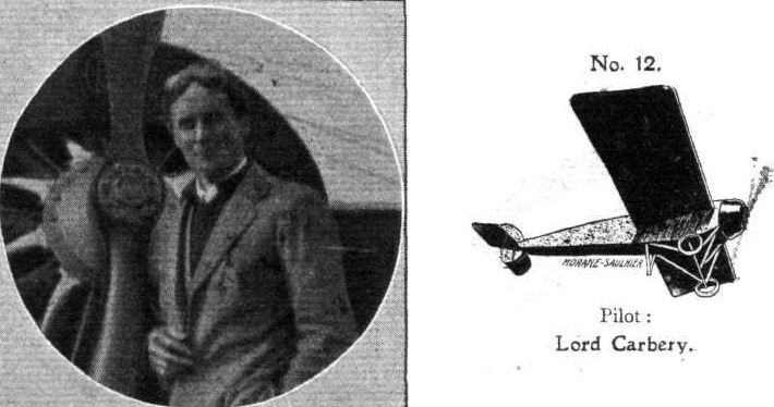
Pilot: Lord Carbery.

Garros in his machine in which be obtained second place in the London-Paris-London Race.
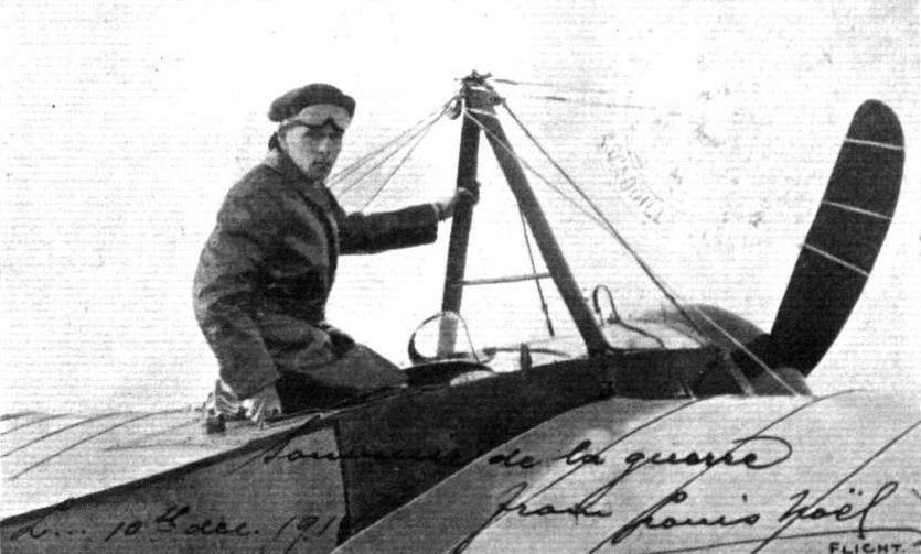
A seasonable card from Louis Noel to hand this week, whose greetings we sincerely reciprocate, both on behalf of ourselves and, we feel sure, of our readers, who have followed in our pages all the good work which he has done here, and is now adding to on the side of the Allies.
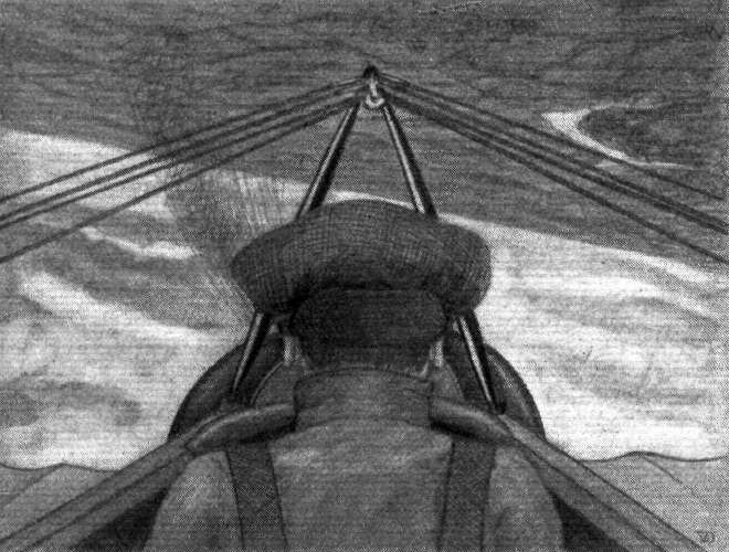
An impression of looping the loop with Noel at Hendon.
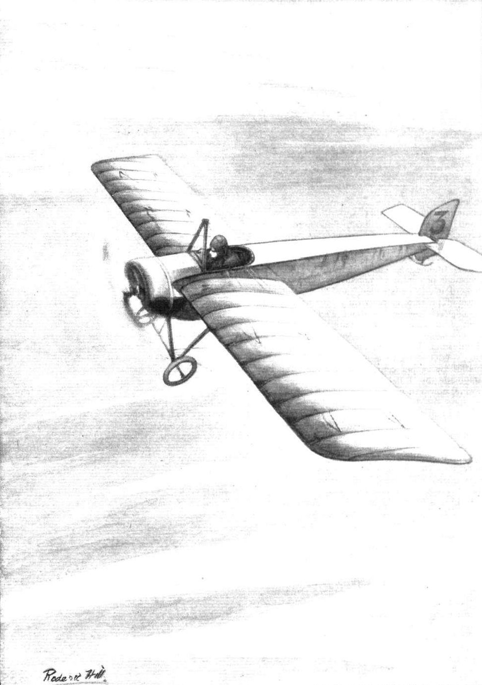
A MEMORY. - Mr. Gustav Hamel, whose disappearance since Saturday has caused such widespread sorrow, flying his Morane monoplane on which he has accomplished such daring feats during the past months. From an original drawing by Roderic Hill.

LONDON-PARIS-LONDON RACE. - The return of Garros; he swept into the aerodrome only to find that he was - second! From an original drawing by Roderic Hill.
Diagrams illustrating simple wireless telegraphy sets. Fig. 1. - The simplest form of transmitting and receiving set. Fig. 2. - The transmitting set of a more modern system. Fig. 3. - The receiving set for the same system.
Fig. 4. - Sketch showing the fitting of a "counterpoise," which takes the place of "earth" on a biplane; also showing the transmitting and receiving aerial.
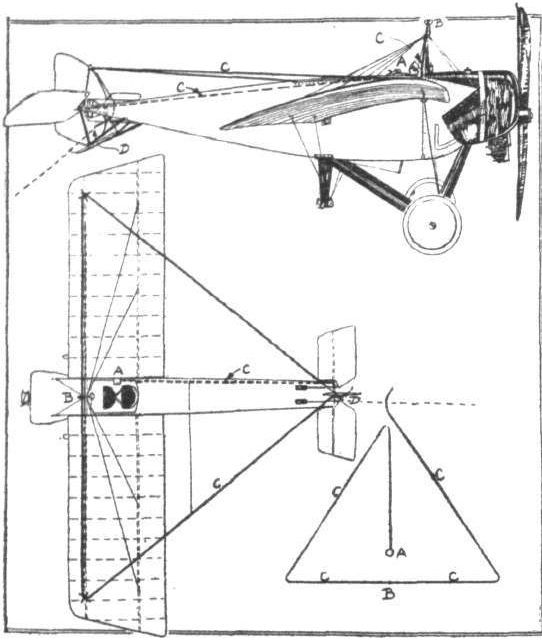
Fig. 5. - Sketch showing the Marconi method of fitting the aerial to a Morane-Saulnier monoplane.

Fig. 6. - Detail views of the three Marconi units as fitted to a Morane-Saulnier monoplane. A, high frequency alternator and rotary disc-discharger. B, transmitting unit; 1, transformer; 2, choke coils; 3, condensers; 4 , jigger primary; 5, jigger secondary: 6, disc-discharge terminals; 7, aerial and counterpoise terminals. C, receiving unit: 2, batteries ; 3. battery cut-out; 4, telephones; 5, operating key; 6, aerial tuning inductance; 7, detector-crystal holder; 8, switches; 9, valvetuning condenser: 10, intensifier; 11, potentiometer.
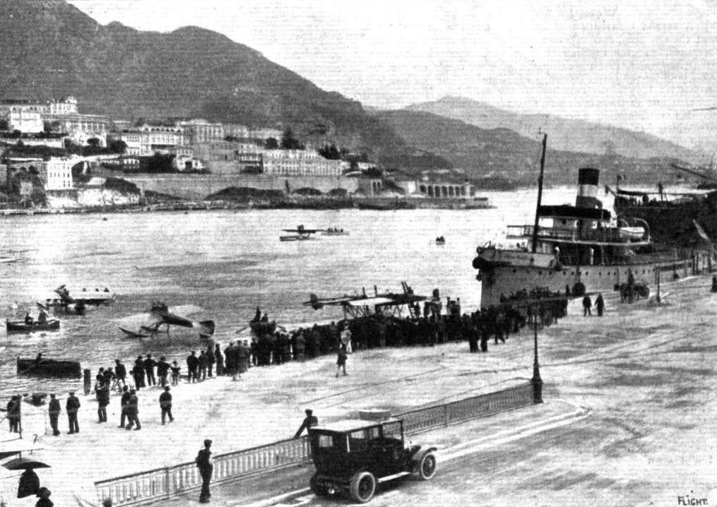
MONACO HYDRO-AEROPLANE MEETING. - A general view of the bay. On the landing stage are seen the two Morane-Saulniers of MM. Garros and Brindejonc de Moulinais, and on the water are a couple of other competitors, whilst the Foudre is seen at the quay on the right.
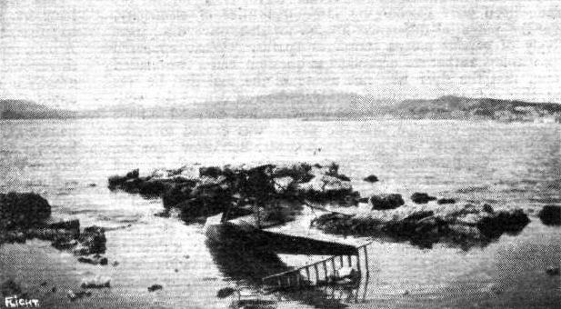
The remains of a wrecked waterplane at Cannes on March 16th, flown by M. Garros and which came to grief on the rocks during the same evening. The photograph shows the remnant of the machine after being partially dismantled, prior to its being carted away.
Flight, January 10, 1914.
THE PARIS AERO SALON - 1913.
MORANE-SAULNIER.
THE Morane-Saulnier exhibit is one of the most artistically arranged, as well as being very interesting, from a technical point of view. The three machines shown are a single-seater similar to the machine flown by M. Garros across the Mediterranean, a tandem two-seater military monoplane, and the "Parasol." Interesting as the two first-mentioned machines are, though they are standard types, we think that the "Parasol" is the most interesting on this stand, as it represents radical alterations in design and construction. It is fitted with a 9-cyl. Gnome monosoupape engine mounted on overhung bearings in the nose of the fuselage. A neat aluminium cowl of the usual Morane type prevents oil thrown out by the engine from being blown back in the pilot's face.
The fuselage is similar to those of the machines now flying at Hendon, and is built up of four longerons of ash converging towards a horizontal knife's edge at the stern. The struts and cross-members are made of ash in the front portion of the fuselage, where the greatest strength is required, and of spruce in the rear part. The chassis is of the ordinary Morane type, which is already known to our readers through descriptions in the columns of FLIGHT. The most striking departure from standard design is in the wings, or rather in the mounting of the wings. Instead of bolting these to the sides of the fuselage, they have been raised a couple of feet above the fuselage, and are mounted on a structure of steel tubes, which converge to form a three-cornered cabane above the wings and which have their lower extremities bolted to the upper longerons of the fuselage. By having the wings mounted in this manner, the machine must of necessity have a very low centre of gravity, but the makers claim that it is very stable and this arrangement certainly has the very great advantage for military purposes, that an unrestricted view of the ground is obtained. Another advantage is that the angle of the lift cables is exceptionally good, the outer cable running to the chassis, whilst the centre and inner cable are taken to the lower longeron and the nose of the fuselage respectively.
Arranged tandem fashion inside a very comfortable cockpit are the pilot and passenger's seats, the pilot being in front. Control is by means of a central tubular column for warp and elevator, and a pivoted foot-bar for the rudder. In front of the pilot are mounted the instruments such as compass, altimeter, speed indicator, clock, revolution indicator, and map case. Let into the floor of the fuselage behind the passenger's seat is a specially constructed camera, the lens of which is pointed vertically downwards. By simply pulling a cord the observer exposes a plate, and when the cord is released the camera automatically changes the exposed negative and substitutes in its stead an unexposed plate. The workmanship of the "Parasol" as well as the other two machines exhibited is of the very highest order, and every detail is beautifully finished. The white fabric on the wings and fuselages in connection with the black enamelled steel parts and engine cowls, renders this exhibit the most graceful at the Show.
Flight, March 14, 1914.
WHAT THERE WILL BE TO SEE AT OLYMPIA.
THE EXHIBITS.
Morane-Saulnier (Grahame-White Aviation Co.). (40)
OF the three machines shown on the stand of the Grahame-White Aviation Co., one will be a Morane-Saulnier monoplane of the "Parasol" type, similar to that which was exhibited at the last Paris Aero Show, when it was described in these columns. It will be the first public appearance of this Morane model in this country, and as it represents a radical departure from usual practice will be well worth a close inspection, especially in view of the excellent flights which have been accomplished on a similar machine in France.
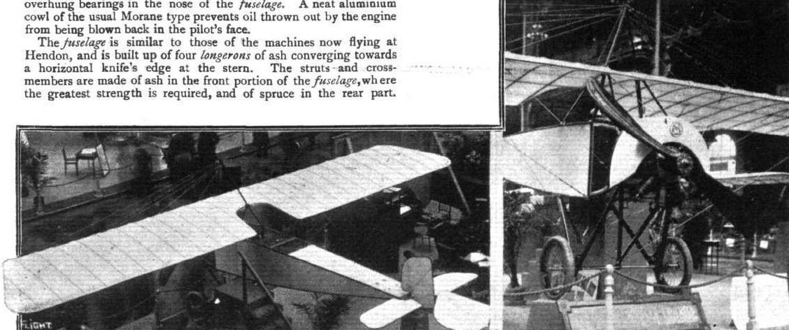
The Morane-Saulnier "Parasol," and a view of the chassis and engine mounting.
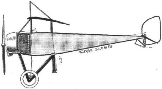
The Morane-Saulnier Parasol.
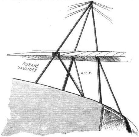
Attachment of wings to fuselage on the Morane-Saulnier "Parasol."
Flight, January 10, 1914.
THE PARIS AERO SALON - 1913.
MOREAU.
On the Emaillite stand was shown the Moreau aerostable, which, it will be remembered, won the Bonnet stability prize. The whole machine seemed unnecessarily complicated, consisting, as it did, of a veritable forest of steel tubes. The automatic stability was purely longitudinal, the shape of the wings being supposed to render the machine automatically stable laterally, although ailerons are fitted. This lateral stability was greatly increased by judicious use of the rudder, as it is quite possible to keep a machine on an even keel without the use of the warp simply by increasing the speed of the dropping wing by turning the machine in the opposite direction. As for the automatic longitudinal stability, this is possessed by nearly every well-designed machine, and is secured simply by means of the longitudinal dihedral angle formed by the difference in the angle of incidence of the wings and the tail plane. In any case one would think that this longitudinal control by means of slinging the pilot's seat could be obtained in a much simpler way.
Constructionally the machine was built of steel almost throughout, the pilot's seat being slung by means of steel tubes underneath the main planes, thus giving the machine a very low centre of gravity.
This was partly counteracted by mounting the engine up in front of and on a level with the leading edge of the wings. On top of the wings was mounted the petrol tank, from which petrol is fed to the carburettor by gravity. The engine was partly covered by an aluminium shield enclosing the lower part of the engine, whilst the upper part had been left uncovered for cooling purposes.
Flight, January 17, 1914.
INVISIBLE AEROPLANES.
ONE important point which the designer of a military aeroplane has to keep in mind is that his machine, when in the air, must be as hard to discern as possible. There have been several attempts to build an aeroplane with the wings of transparent material, and in May and June of 1912, Lieut. Nittner was flying at Wiener Neustadt, near Vienna, an Etrich monoplane, specially built on such lines for Capt. Petroczy, formerly commandant of the flying corps in the Austrian Army. This machine had the planes covered with a special variety of Emaillite cellulose sheets, and the system has since been developed and patented in all countries by MM. Leduc Heitz, of the Paris House of Emaillite. A photograph is reproduced of the Etrich machine, to which reference has been made, and which those present on the ground were unable to locate in the air when flying at an altitude of between 900 and 1,200 ft. It is stated that at a height of 700 ft. only the framework is dimly visible, and this and the outline of the motor and pilot and passengers present so small an area to rifle or gun fire, that at the rate of speed at which aeroplanes are flown to-day, accurate aiming at such surfaces becomes nearly impossible. There are also secondary advantages in the use of such transparent sheeting in the construction of aeroplanes. For one thing, it enables the pilot to keep an eye upon the interior framework of the planes, and to detect at once any straining or fracture of the ribs, &c. Another advantage is that the highly polished smooth surface reduces the friction, as was proved in the case of Capt. Petroczy's machine, although, as that was the first machine to be so treated, the material used was not so suitable as the latest product. The surface could not be properly tightened, and owing to the sheeting being more or less plastic it presented a wavy surface, while some difficulty was experienced in securely fastening it to the ribs.
As long ago as 1904. Prof. Reisner, of Aachen, suggested that polished celluloid should be utilised for aeroplane sheeting in order to diminish air friction.
Last year, M. W. A. Lebedeff, working in conjunction with the Russian Government, tried to cover a Henry Farman biplane with transparent cellulose sheeting of a somewhat modified composition. This material was not so heavy as that used in Austria, and it was also somewhat stronger (its tensile strength being about 7 kilogs. Per square millimetre of section), but the wavy surface of the wings, due to the flexibility of the material, could not be overcome.
After working at the problem for some time the Emaillite firm have developed a better material which was seen at the Paris Show on the planes of the Moreau monoplane. Instead of using ordinary cellulose sheeting, this machine has what might be termed a reinforced sheeting consisting of two layers of Emaillite with a sheet of silk tulle between them, the tulle being specially treated to render it transparent. That the material is to all intents and purposes transparent is illustrated by the photographs of one of the wings of the Moreau monoplane behind which a man can be clearly seen. The use of the tulle liner not only strengthens the material but it also prevents it sagging or warping between the ribs so that by its use it is quite possible to obtain a smooth and regular surface on the planes. The tensile strength of the material is about nine to ten kilogs. per square millimeter section and a 35 mm. sheeting is sufficient to ensure a tensile strength of about 2,800 to 3,000 kilogs. of the wing covering, a stress which is never attained with the best fabrics in use. The weight of this new Emaillite material does not exceed 375 grammes per square metre, which is but 40 per cent, more than the weight of good doped linen fabric as generally used, so that the increase of weight in the case of ordinary machines would be between 12 and 15 kilogs. It is claimed for this new Emaillite transparent reinforced sheeting that it has all the advantages of that which is not reinforced without its faults. It can be fastened either by nailing, sewing, or by using an adhesive solution. It will not tear or break when anything such as a tool falls upon it, while should it be pierced by a bullet the fabric liner would prevent the damage extending. The British patents for this invention are held by the British Emaillite Co., Ltd., of 30, Regent Street, W. Extensive tests are shortly to be carried out with machines covered in this way, in order to ascertain the height at which they become virtually invisible.
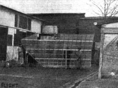
A wing of the Moreau aeroplane which was at the Paris Salon. It will be seen that the man standing behind the planes is as visible as the one in front.

A FEW OF THE MACHINES COMPETING IN THE "CONCOURS DE LA SECURITE" EN AEROPLANE." - 4. The Moreau "Aerostable," which was exhibited at the last Paris Aero Show, when we gave a description of it.
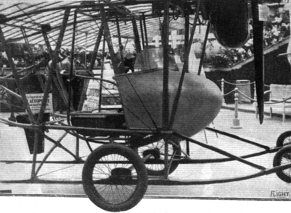
The Moreau " Aerostable."
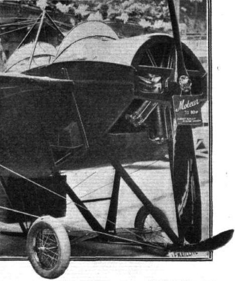
The tandem-seater military Nieuport.
THREE HISTORIC MACHINES IN LINE AT HELIOPOLIS. - In the centre is Marc Pourpe's 60 h.p. Gnome-Morane-Saulnier, which he flew from Cairo to Khartoum and is now flying back - this is the identical machine on which Garros crossed the Mediterranean on the left is Vedrines 80 h.p. Gnome Bleriot which was flown from Paris to Cairo; while on the right is Bonnier's 80 h.p. Gnome-Nieuport, which has also been flown from Paris to Cairo.
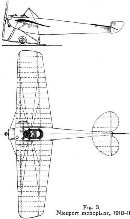
Fig. 3. Nieuport monoplane, 1910-1911.
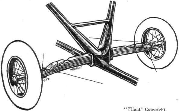
The leaf spring of the Nieuport tandem two-seater.
Fig. 2. - Sections of tail planes: A, Avro tail, 1910-11. B, Nieuport tail, 1910-11. C, B.E. tail, 1911. D, B.E. tail, 1912.
Flight, March 14, 1914.
WHAT THERE WILL BE TO SEE AT OLYMPIA.
THE EXHIBITS.
Nieuport (England) Ltd. (65.)
ON this stand there will be two machines, one a single-seater monoplane and the other an 100 h.p. hydro-aeroplane, both of which are, of course, tractor machines. These machines will be similar in design to those exhibited at the Paris Aero Show in December last, and the hydro-aeroplane will, in general, follow the usual construction embodied in the Nieuport monoplanes, that have set up such excellent performances in the past, concerning which we would venture to mention the long-distance flight of Helen for the Michelin prize, and the height record established by Legagneux. But the single-seater machine will depart somewhat from Nieuport practice, principally, however, in regard to the landing chassis, and in the shape of the wing surfaces, to which, however, we referred in our report on the Paris Exhibition. The standard type of hydro-aeroplane is fitted with an 80 h.p. Le Rhone engine, and the prices at which the two machines are listed are L1,080 and L2,000 respectively.
The skimmer, which will complete the exhibit, is fitted with a 160 h.p. engine, and a propeller having a diameter of 3 metres, which are mounted on a tubular steel framing. The buoyancy apparatus is in three parts, formed by a central hull and two side floats - the angle of incidence of the steps on the latter being capable of variation by means of gearing. The side floats are more deeply immersed than is the hull, so that when a speed of about 32 miles per hour is attained, the central hull is lifted clear of the water, and, consequently, a great increase of speed is permitted, the angle of incidence of the steps being made to correspond with the speed at which the craft is moving.
Flight, March 28, 1914.
THE OLYMPIA EXHIBITION.
THE EXHIBITS.
NIEUPORT (NIEUPORT (ENGLAND), LTD.).
OF the two machines shown on the Nieuport stand the 100 h.p. seaplane follows fairly closely the lines of the seaplane exhibited at Olympia last year, whilst the second machine, a 60 h.p. military scout, differs considerably from usual Nieuport practice.
The 100 h.p. Seaplane is fitted with a 9-cylinder 100 h.p. Gnome engine mounted on overhung bearings in the nose of the fuselage. The latter is built up in the usual way of longerons of ash, with struts and cross members of spruce, and is entirely covered in as in previous Nieuport machines. Inside the very roomy cockpit are arranged the pilot's and passenger's seats, tandem fashion, the pilot occupying the rear seat. The controls are of the usual Nieuport type, with the exception that the warp is now connected up to the hand lever, whilst the rudder is operated by a foot-bar. It will be remembered that in the earlier models the warp was operated by the foot-bar, whilst the rudder was actuated by swinging the hand lever from side to side.
The usual set of instruments is fitted, and in addition there is an engine primer which is operated from the seat and a special retarded magneto for starting the engine. As soon as the engine starts firing this magneto is automatically de-clutched, and the ordinary magneto brought into action. When the engine has been primed it is started by means of a hand lever in front of the passenger's seat.
The wings are built up of ribs having three-ply webs and ash flanges over steel tube spars. The front spar fits into a tubular socket on the fuselage, whilst the rear spar is hinged. The ribs have a slight amount of play, thus allowing them to rotate slightly round the spars when the wings are warped, thereby considerably reducing the strains on them. The lift and drift wires take the form of very stout stranded cables attached to a pylon underneath the fuselage. The top pylon consists of a pyramidal structure of steel tubes. By means of the bolt shown in one of the accompanying sketches, the upper bracing wires are tightened or slackened, so that once the wings have been properly adjusted all that is necessary in order to dismantle them is to undo the bolt until the cables are sufficiently slack to allow of their being removed. Thus the wings can be erected or dismantled without interfering in the slightest with their adjustment.
The main floats, of which there are two, are of a peculiar shape, having a wide three-stepped keel, from which the bottom slopes outwards and upwards, whilst close to the tides of the boat it returns to the horisontal. The floats are built up of three-ply bottoms and two-ply sides, whilst the top is covered with canvas. All the chassis struts are streamlined steel tubes, of which the upright ones we internally reinforced.
The tail planes are of the usual Nieuport type, consisting of a semi-circular stabilising plane to the trailing edge of which are hinged the two semi-circular elevator flaps. The rudder is hinged to an extension of the sternpost of the fuselage, and vertical fins are fitted both above and below the fuselage in order to counteract the large side area in front. An egg-shaped metal float supports the tail planes when the machine is at rest. The fuel capacity of this machine is 3 1/2 hours, but we understand that the Nieuport firm is bringing out another seaplane, also a two-seater, which has a capacity of five hours' flight, and a single-seater carrying sufficient fuel for a flight of six hours' duration.
<...>

Nose and chassis of Nieuport hydro.
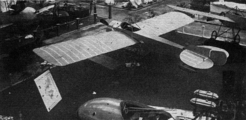
The Nieuport stand.
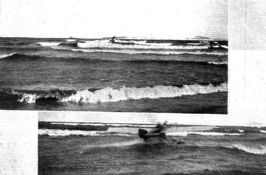
A REMINISCENCE OF THE MONACO AERIAL RALLY. - A couple of snaps during the competition of M. A. Mallard on his Nieuport waterplane at Marselles.
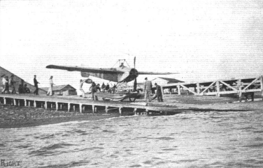
AT THE FREJUS NAVAL AIR STATION. - Launching a Nieuport waterplane. The method adopted is to warp it out to an anchored buoy about 100 yards from thi shore; the cradle on which it travels on land is then unlashed and sinks, to be drawn in shore later, the pilot starting the engine himself from the seat.
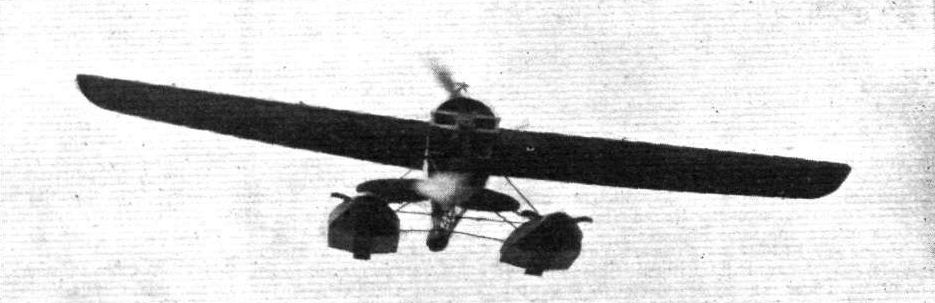
A Nieuport hydro-aeroplane in full flight.

Seaplane flying at St. Raphael, the French Mediterranean aviation station. - Levasseur flying a Nieuport.
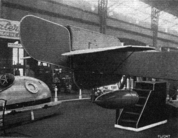
Tall planes and float of Nieuport hydro.
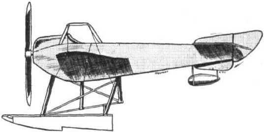
The 100 h.p. Nieuport seaplane.
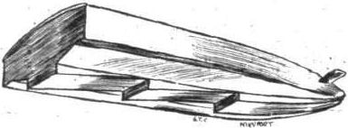
View from underneath of one of the Nieuport floats.
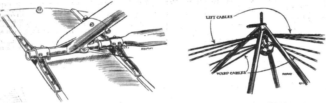
ATTACHMENT OF FLOAT TO CHASSIS ON NIEUPORT HYDRO. - On right upper pylon.
Flight, January 3, 1914.
THE PARIS AERO SALON - 1913.
NIEUPORT.
THE Nieuport firm made an impressive show with four monoplanes and a Nieuport-built Dunne biplane. One of the machines, and not the least interesting, was the one on which Helen recently covered a distance of some 20,000 kilometres. The machine, although naturally somewhat dirty, did not seem any the worse for its constant exposure to all sorts of weather conditions, and furnished an excellent proof of the quality of the Nieuport workmanship.
Of the other machines shown, one was an armoured monoplane of the Military type, and fitted with a Hotchkiss machine gun. The front portion of the fuselage, up to just behind the seats, is covered with sheet steel, and a cowl of the same material is fitted on the propeller boss with which it revolves, so that there is veiy little chance of a bullet hitting any part of the engine, and thereby putting the machine out of action.
It is driven by a 14-cyl. 160 h.p. Gnome engine, mounted on double bearings. The fuselage, which is of the usual deep Nieuport section, is built up of four longerons of ash, connected by struts and cross-members of spruce.
Inside this roomy fuselage are arranged the seats for the pilot and two passengers, the pilot's seat resting on a large petrol tank in front and the passengers' seats arranged side by side behind him. The set of instruments fitted is one of the most complete seen on any of the machines at the Show. The chassis is of the usual Nieuport type, consisting of three pairs of V-struts of streamline steel tubes, which carry on their lower extremities a tubular skid, whilst springing is effected by means of a leaf spring-axle carrying the two wheels. A rocking shaft sloping down from the fuselage to a bearing behind the rear pair of chassis struts carries a crank lever, to which are attached the warping cables. On the upper end of this rocking shaft is mounted a transverse foot-bar, by means of which the wings are warped. A single tubular lever is used for operating rudder and elevator. The main planes are of the usual Nieuport section, and taper considerably towards the tip. The fixed tail plane, which is of semi-circular shape, is mounted on top of the fuselage and to its trailing edge are hinged the two elevator flaps. The rudder, which projects tome distance above the tail plane, is pivoted to a steel tube forming the stern post of the fuselage.
Of the other machines shown, one is a tandem two-seater Military monoplane, which is driven by an 80 h.p. 7-cyl. Clerget engine, mounted on double bearings in the front portion of the fuselage. This machine follows in every respect the usual Nieuport practice. The seats for the pilot and passenger are arranged tandem fashion, the passenger's seat in front being mounted on one side of the fuselage, so that he is facing towards the right-hand wing. The object of this arrangement is not quite clear, but the idea is presumably to give the pilot a more unobstructed view straight ahead. The two seats are arranged, each in its own cockpit, each occupant being protected by a wind-screen of large dimensions.
<...>
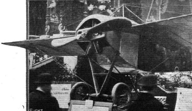
HELEN'S NIEUPORT MONOPLANE WHICH HAS COVERED A DISTANCE OF ABOUT 20,000 KILOMS.
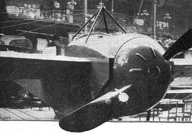
THE NOSE OF THE ARMOURED NIEUPORT MONOPLANE.
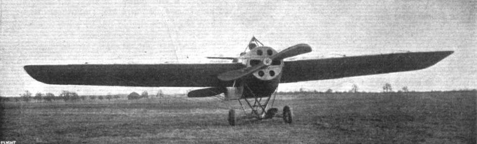
THE ARMOURED NIEUPORT MONOPLANE WHICH HAS DONE SO WELL DURING ITS TRIALS. - This machine is covered in front with special nickel-steel armour plate of 3 mm. thickness. The chief characteristics are: Span, 40 ft. 6 ins.; length 26 ft. 6 ins.; area, 261 sq. ft.; weight, empty, 1,433 lbs.; useful load includes pilot, gunner, gun and ammunition with petrol for 2 hours; engine, 160 h.p. Gnome; diameter of propeller, 8 ft. 9 ins.; speed with full load, 74.5 m.p.h.; climbing 1,640 ft. in 7 mins.; starting after run of 328 ft.; alighting and stopping after run of 262 ft.
Flight, January 3, 1914.
THE PARIS AERO SALON - 1913.
NIEUPORT.
<...>
The remaining monoplane is slightly different from the usual Nieuport machines, and is somewhat reminiscent of the Morane-Saulnier monoplane, this resemblance more especially applying to the chassis and engine housing. It is fitted with a 7-cyl. 60 h.p. Le Rhone engine, mounted on overhung bearings.
The cockpit in which is situated the pilot's seat seems very comfortable, and similarly to the other Nieuport machines, no trouble or expense seems to have been spared in order to make the instrument board as complete as possible. The controls in this machine differ from the usual Nieuport practice in that the hand-lever is used for warping and a foot bar for operating the rudder.
<...>
Flight, March 14, 1914.
WHAT THERE WILL BE TO SEE AT OLYMPIA.
THE EXHIBITS.
Nieuport (England) Ltd. (65.)
ON this stand there will be two machines, one a single-seater monoplane and the other an 100 h.p. hydro-aeroplane, both of which are, of course, tractor machines. These machines will be similar in design to those exhibited at the Paris Aero Show in December last, and the hydro-aeroplane will, in general, follow the usual construction embodied in the Nieuport monoplanes, that have set up such excellent performances in the past, concerning which we would venture to mention the long-distance flight of Helen for the Michelin prize, and the height record established by Legagneux. But the single-seater machine will depart somewhat from Nieuport practice, principally, however, in regard to the landing chassis, and in the shape of the wing surfaces, to which, however, we referred in our report on the Paris Exhibition. The standard type of hydro-aeroplane is fitted with an 80 h.p. Le Rhone engine, and the prices at which the two machines are listed are L1,080 and L2,000 respectively.
The skimmer, which will complete the exhibit, is fitted with a 160 h.p. engine, and a propeller having a diameter of 3 metres, which are mounted on a tubular steel framing. The buoyancy apparatus is in three parts, formed by a central hull and two side floats - the angle of incidence of the steps on the latter being capable of variation by means of gearing. The side floats are more deeply immersed than is the hull, so that when a speed of about 32 miles per hour is attained, the central hull is lifted clear of the water, and, consequently, a great increase of speed is permitted, the angle of incidence of the steps being made to correspond with the speed at which the craft is moving.
Flight, March 28, 1914.
THE OLYMPIA EXHIBITION.
THE EXHIBITS.
NIEUPORT (NIEUPORT (ENGLAND), LTD.).
OF the two machines shown on the Nieuport stand the 100 h.p. seaplane follows fairly closely the lines of the seaplane exhibited at Olympia last year, whilst the second machine, a 60 h.p. military scout, differs considerably from usual Nieuport practice.
<...>
60 h.p. Nieuport Military Scout. This machine is fitted with a 7-cyl. 60 h. p. Le Rhone engine, mounted on overhung bearings, and partly covered in by an aluminium shield. The chassis differs considerably from previous Nieuport models, and bears a certain resemblance to the chassis of the Morane Saulnier monoplanes. The chassis is built of steel tubes throughout, and has a tubular axle carried in the angle between the struts, and slung by means of rubber shock absorbers. Constructionally it resembles the seaplane, but the fuselage has been reduced considerably in width and depth. Only a single seat is fitted, and from here the pilot controls the machine by means of a single central hand-lever and a rudder foot-bar.
The main planes are of the usual Nieuport section, which has proved so efficient, and are built up in a similar manner to that of the bigger machine. The tail planes consist of a semi-circular stabilising plane mounted on the upper longerons of the fuselage, a divided elevator, and a non-balanced rudder. The tail planes are easily detachable, and fitted with hooks, by means of which they can be suspended from the upper longerons of the fuselage for purposes of storage or transport.
A small tail skid of rather unusual shape protects the tail planes against contact with the ground. It consists of a cone-shaped piece of sheet steel which takes the place of the usual extension of the stern post of the fuselage, and carries the small pivoted rubber-sprung skid.
In addition to the two machines described above, there is shown on this stand a 100 h. p. skimmer of the stepped type, a craft which has already attained a certain amount of popularity in France, and which should, we think, provide quite a lot of sport if taken up in this country.
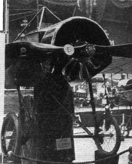
The Nieuport single-seater.
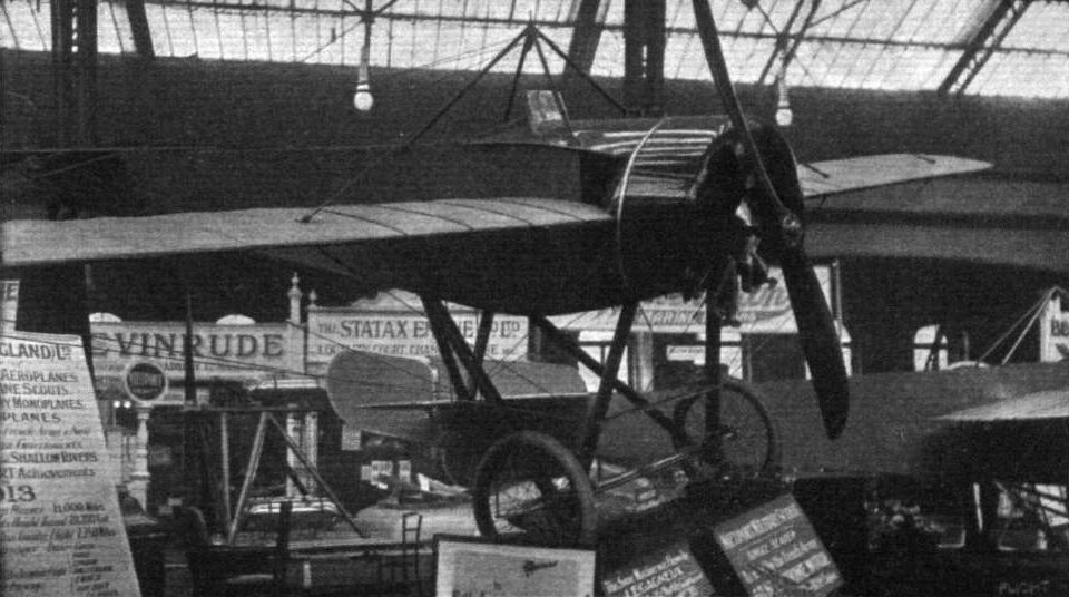
The Nieuport military scout.
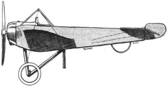
The 60 h.p. Nieuport single-seater.
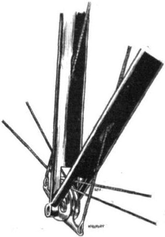
Lower pylon of Nieuport scout.
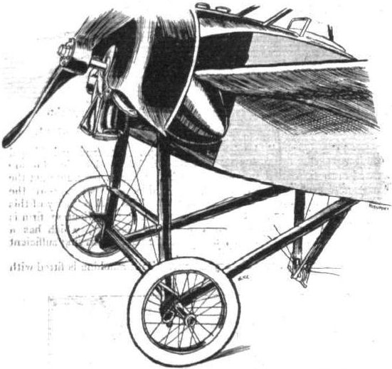
Chassis and engine housing on Nieuport scout.

DETAIL OF CHASSIS ON NIEUPORT. - On right shock absorber and radius rod.
Flight, January 17, 1914.
THE PARIS AERO SALON - 1913.
PONNIER
The two Ponnier monoplanes exhibited were evidently built for speed, one of them being similar to the monoplane flown by Emile Vedrines in the Gordon-Bennett race. This machine was fitted with a 100 h.p. Gnome engine, carried between double bearings, of which the front one was easily detachable. The chassis had been reduced to its simplest possible form, consisting of two pairs of V struts of streamlined steel tubes, carrying a single axle on which are mounted the wheels. No provision whatever had been made for springing these, so that the achine must be very tricky to land on anything but the smoothest of surfaces.
The other machine, which was similar in general lines, was fitted with wings of much bigger span, and the chassis was of a more useful type, the wheels being sprung in the usual way by rubber shock absorbers.
Constructionally the two machines consisted of a very deep fuselage built up of four longerons of ash, connected by struts and cross-members of spruce.
The method of joining these to the longerons was such that the longerons are not weakened by piercing. The tail planes are built up of steel tubes.
The upper stay wires of the wings were attached to the top of a triangular pyramid in such a manner that they could be quickly dismantled, and the lower lift-wires were secured to a quadrangular pyramid, which was independent of the landing chassis. Control was effected by a single hand-lever for warp and elevator, and a foot-bar for the rudder. One gathers that in the future the Ponnier monoplanes will probably be built of steel throughout, SO that this firm must now be added to the ever-increasing list of aeroplane manufacturers who favour steel as a material for aeroplane construction in preference to wood.
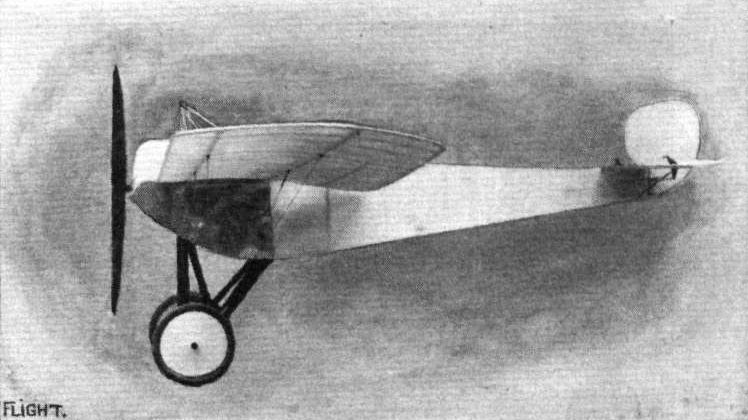
The 60 h.p. Ponnier monoplane.
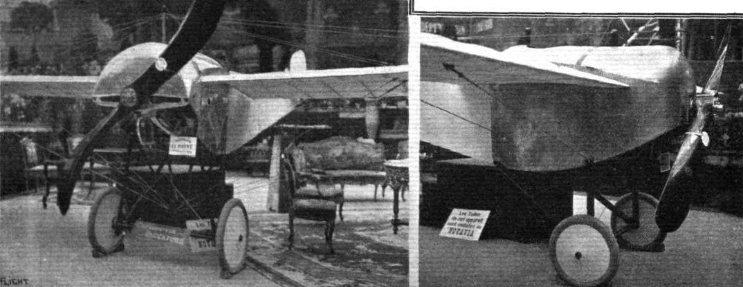
CHASSIS AND ENGINE HOUSING OF THE 60 H.P. PONNIER. - On the right the nose of the 160 h.p. Ponnier-type Gordon-Bennett.
Flight, August 14, 1914.
THE PONNIER SCOUTING BIPLANE.
UP to the time of the winning, by Pixton on the small Sopwith biplane, of the Schneider Cup, French designers confined their attention, when high speeds were desired, to the monoplane type of machine. Their efforts in this direction were crowned with a considerable amount of success, as evidenced by me performances of the Deperdussin and Ponnier monoplanes, piloted by Prevost and Vedrines respectively, in last year's Gordon-Bennett race at Rheims. But whereas the maximum speed attained by these racing machines was very high, the speed variation was practically negligible, and it was not until the excellent performances of the Sopwith biplane brought home very forcibly to French designers the possibilities of a small, fast biplane, that this type was taken up in France. Since then, however, several French constructors have, at the request of the Government, we believe, produced scouting biplanes of the type originated in this country by the Sopwith Aviation Co., Ltd.
In the case of the Ponnier biplane, of which we publish illustrations this week, the step from monoplane to biplane was not a very long one, since the particular type of fuselage employed in the former was eminently suitable for the latter. Practically the only alteration necessary was that of substituting two pairs of wings for one pair, and arranging them in such a manner that the balance of the machine was preserved, and the scouting biplane was evolved.
The fuselage is identical with that of the cavalry type monoplane exhibited at the last Paris Aero Show, when it was fully described in our columns. It is of rectangular section and built up of four ash longerons connected by struts and cross members, the whole being made rigid by means of the usual cross wiring. In front the longerons converge until they meet the rear engine-bearer. From here the tubular extensions of the longerons are swept outwards to clear the engine and carry on their front extremities the front engine-bearer, which is of the usual pressed steel type.
As in the monoplane, the fuselage is entirely covered in, the rear portion being covered with fabric, whilst the nose of the machine up to the pilot's seat is enclosed by aluminium sheeting, the front portion of which forms a cowl over the front and upper half of the engine. At present a 50 hip. Gnome is fitted, but by slightly enlarging the cowl an 80 or 100 h.p. Gnome could easily be accommodated.
In plan view the main planes are similar to those of the Ponnier monoplane, tapering considerably towards the tips. In section they are characterised by a Philips entry, and a very pronounced return of the trailing edge. The wings are unusually thick, and thus allow of fitting spars of great depth, which again makes for strength of construction, and enables the number of interplane struts to be reduced to two on each side. These struts are steel tubes of excellent streamline section, and cross bracing is effected by means of stout stranded cables, terminating in quick release devices, which greatly facilitate erecting and dismantling of the wings. The angle of incidence diminishes considerably towards the tips, a fact to which the constructors attribute, in great part, the stability of the machine.
The type of chassis employed in the Ponnier monoplane has been retained, and consists of two pairs of struts, each pair of which forms a V as seen from the side. The apices of the two V's are connected by a tubular axle, working in slots in a plate which is welded into the angle between the front and rear tubular struts. Lateral stiffness of the chassis is provided by cables running from the upper end of one chassis strut to the lower end of the strut opposite, as will be seen from the front view of the machine. Springing is by means of rubber shock-absorbers wound round the axle and anchored to a short length of steel tubing welded on to and projecting out from the apex of the chassis struts.
From the pilot's seat an exceptionally good view for a machine of this type is obtained. It is stated by the constructors that the downward angle of vision is 20°, or, in other words, that when the machine is flying at a height of 1,000 ft., the pilot is able to see the ground as far back as a point 400 ft. in advance of a point vertically below him. By cutting away the trailing edge of the centre portion of the upper plane, a good view is obtained in an upward direction, so that it is only in a forward and upward direction that the view is obscured.
Control is by means of a foot-bar for the rudder, and a rotatable hand wheel for warp and elevator. The fixed tail plane, which is of the flat non-lifting type mounted on top of the fuselage, is constructed of a framework of steel tubes, as are also the elevator and rudder. A tail skid of the type shown in one of the accompanying sketches, protects the tail planes against contact with the ground. The weight of the machine empty is 570 lbs., and the maximum and minimum speeds are 65 and 33 miles per hour respectively. With a 50 h.p. engine the machine climbs to an altitude of 1,000 metres (3,281 ft.) in 8 mins., with a load of 350 lbs.
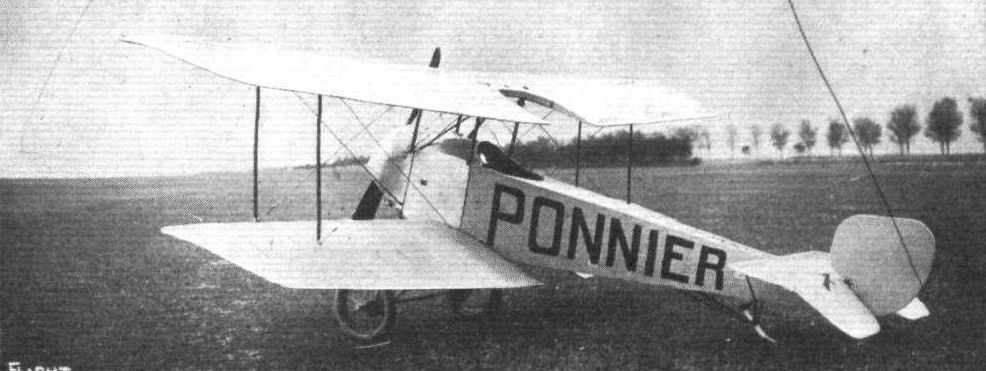
A three-quarter view from behind of the Ponnier biplane.
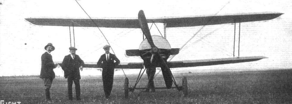
The Ponnier biplane, as seen from the front.
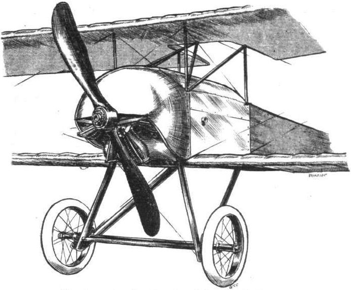
Chassis and engine housing of Ponnier biplane.
Tail planes of the Ponnier biplane.
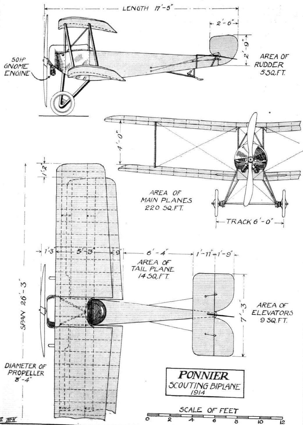
THE PONNIER SCOUTING BIPLANE. - Plan, side and front elevations to scale.
Flight, January 17, 1914.
THE PARIS AERO SALON - 1913.
RATMANOFF AND DE BEER.
On the Ratmanoff stand were to be seen two monoplanes, one of which was a Ratmanoff school type monoplane. It is' fitted with a 45 h.p. Anzani engine, and the machine itself is built on quite orthodox lines. There is nothing remarkable about the machine, and it is simply a straightforward well-built machine for all-round work, and is sold at the reasonable price of L600.
<...>
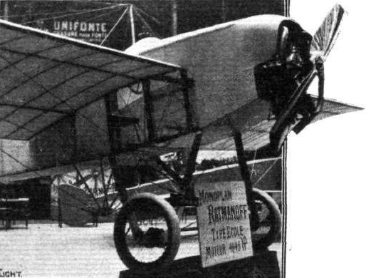
The Ratmanoff monoplane.
Flight, January 10, 1914.
THE PARIS AERO SALON - 1913.
R.E.P.
To most of the visitors to the Paris Show it was a surprise to find that the R.E.P. firm were showing, in view of the fact that Mr. Robert Esnault-Pelterie definitely retired from aeroplane construction last year. However, one was glad to see that he had been induced to alter this decision, as it would have been a great loss to aviation generally if the withdrawal had been permanent. Of the two machines shown, one was a single-seater monoplane, fitted with an 80 h.p. Gnome engine, which did not differ materially from the earlier R.E.P. machines, already known to our readers. It was built of steel tubes throughout, and the high quality of the workmanship was readily appreciated after an inspection of the skeleton fuselage which completed the exhibit on the R.E.P. stand. The joints were not soldered, but were in most cases either bolted or welded by acetylene welding. Control was by means of a single central lever for the warp and elevator, and a foot-bar for the rudder.
The chassis was sprung in the usual R.E.P. way by a cross-arm sliding up along one of the struts in the side of the fuselage, and carrying the rudder shock absorbers, and the wheels were carried on two stub axles pivoted on the lower longeron on the fuselage. The wings were supported on the fuselage by fitting the spars in hinged lugs, so that no bending strain was imposed upon the rear spar when warping the wings. The upper bracing cables to the front spar were attached to the top of a triangular pyramid formed by steel tubes, whilst those to the rear spar were attached to a single tube. They do not run over pulleys in the usual manner, but were fixed rigidly to the tube which rocks laterally when the wings were warped. The lower front lift wires were secured to the keel of the fuselage, on which were also situated the pulleys for the lower warp wires.
The whole machine had been designed with a view to facilitate dismantling, and all parts had been standardised so that in case any part becomes damaged it could be easily and quickly replaced.
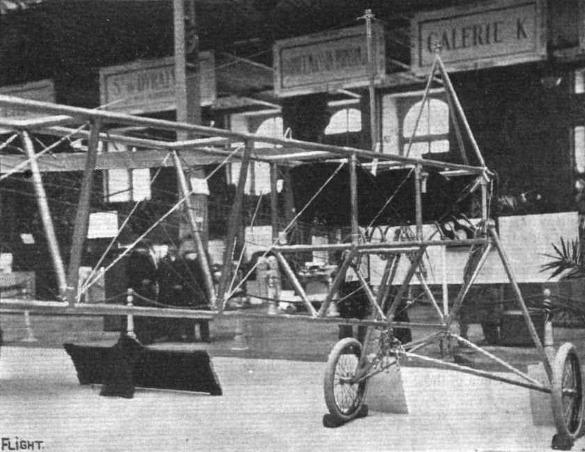
The skeleton of the all-steel R.E.P. fuselage.
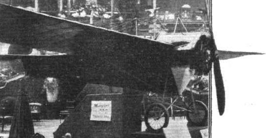
The R.E.P. monoplane.

A FEW OF THE MACHINES COMPETING IN THE "CONCOURS DE LA SECURITE" EN AEROPLANE." - 3. The R.E.P. monoplane, total visibility type, which is fitted with standard control.
Flight, January 17, 1914.
THE PARIS AERO SALON - 1913.
PAUL SCHMITT.
ON the same stand as the Morane-Saulnier monoplanes, but forming a separate exhibit, was the Paul Schmitt biplane, the most interesting feature of which was the provision made for altering the angle of incidence. This machine, which was built of steel throughout, was fitted with a 14-cyl. 160 h.p. Gnome engine, mounted on double bearings in the front of the fuselage. The fuselage, which was built up of steel tubes, was of rectangular section in the front portion, gradually tapering to a triangular section at the rear. In front of the main planes was a very roomy cockpit containing the passengers' seats, which were placed side by side. Access to this cockpit was gained through a door in the side of the fuselage, and the spacious cockpit reminded one more of a motor car than of an aeroplane. The pilot's seat was situated out behind the main planes, and in front of him were the two wheels by means of which the angle of incidence could be altered while the machine is in flight, as well as the ordinary control levers, which consist of a single central lever for ailerons and elevator, and a pivoted foot-bar for the rudder. It is, perhaps, a debatable point whether it is of any great advantage to be able to vary the angle of incidence during flight, and practical tests of this machine will therefore be of great interest. From the accompanying diagrammatic sketch the principle of the system employed for varying the angle of incidence will be easily understood, and the method of carrying it out appears to be a mechanically sound piece of work.
The range of variation in the angle of incidence is from 0 to 12 degrees, and the wings may be moved through that arc in the space of a few seconds. By increasing the angle of incidence and at the same time throttling down the engine, the minimum speed is obtained, while decreasing the angle of incidence and opening out the throttle increases the speed of the machine. The chassis, which was built up of steel tubes throughout, was of the wheel and skid type, the four wheels being carried on a single axle sprung from the skids in the usual way by means of rubber shock absorbers. The tail planes consist of a large balanced elevator and a divided rudder, no fixed tail plane being fitted. A pivoted tail skid protects the tail planes against contact with the ground.
Flight, April 18, 1914.
THE PAUL SCHMITT BIPLANE.
AT the time of the Paris Show we gave a full description of the Paul Schmitt biplane, with an illustration of the method whereby the angle of incidence may be altered during the flight. The recent excellent performances of this machine in the hands of M. Garaix, who, it will be remembered, has beaten the world's height record with six, seven, eight and nine passengers, seem to prove the advantage of the variable angle of incidence in conjunction with its complement, the variable power. It will be noticed that when the angle of incidence is maximum the inter-plane struts slope backwards in relation to the fuselage, thus providing a rearward stagger of the planes. It might appear at first sight that the alteration of the angle of incidence by pivoting the planes round the transverse horizontal axis would lead to displacement of the centre of gravity, but this possibility has been guarded against by so calculating the position of the transverse axis around which the planes are pivoted that the resultant centre of pressure for both planes remains the same, with regard to the centre of gravity, throughout the entire series of alterations of the angle of incidence which ranges from 0° to 12°. The machine is fitted with a 14-cyl. 160 h.p. Gnome engine driving an Integral propeller.
Flight, October 30, 1914.
THE PAUL SCHMITT BIPLANE.
EVER since the early days of aviation, aeroplane designers have realised the advantages to be derived from the use of a variable angle of incidence with its complement, the variation in power, when a good speed range was desired. The solution of the problem of a variable angle of incidence, however, presents certain constructional difficulties which have, no doubt, caused a great number of designers to take the line of least resistance and produce machines in which the angle of incidence remained fixed in relation to the body, but which were capable of a considerable speed variation by altering the flying attitude of the whole machine. That this method of obtaining speed variation does not and cannot give maximum efficiency throughout the entire range of speeds will be readily understood, when it is realized that in a machine having its wings set at a fixed angle of incidence there is only one speed at which the maximum efficiency is obtained, namely, the speed in horizontal flight at which the machine flies with its body horizontal.
Any change in the speed caused by a variation in power through the intermediary of an alteration of the angle of incidence (the flight path is assumed to be horizontal) necessitates a change in the attitude of the whole machine, which again means that the line of flight is no longer parallel to the centre line of the body. The result is that the air, instead of flowing along the top and bottom of the body and causing skin friction only, strikes it at an angle - on top at higher speeds, and on the bottom at lower speeds, and in both cases presenting a certain amount of detrimental surface.
For example, suppose a machine, flying with its fuselage horizontal, will maintain a horizontal flight path with its engine on three-quarter throttle. Now, if the throttle is opened fully the angle of incidence will have to be diminished in order to keep the flight path horizontal, or, in other words, to prevent the machine from climbing. As the angle of incidence is fixed it can only be diminished by changing the attitude of the whole machine, that is to say, by letting it fly "tail high."
Again, for flying at low speeds the engine is throttled down, and the angle of incidence increased by letting the machine fly cabre - i.e., with the tail down, a position which always carries with it the possible danger of a tail slide in case of engine failure. In both cases the air, instead of causing skin friction only, exerts a pressure on the detrimental surface presented by the top or bottom of the body in the "tail high" or "tail low" position respectively. The attendant disadvantages of securing speed variation by altering the flying attitude of the machine has not been dealt with exhaustively in the above, as to do so would be outside the scope of this article, but it will give an idea of the raison d'etre of the variable incidence machine.
As already mentioned, there are certain constructional difficulties which militate against the satisfactory solution of the problem of the variable angle of incidence, but the Paul Schmitt biplane, which was exhibited at the last Paris Aero Show, and which is not, as might be inferred by its name, a German but a French production, is the most practical attempt that has yet been made to overcome the difficulties. Since the method employed of altering the angle of incidence is the most interesting feature of this machine it will be dealt with first.
From the accompanying illustrations it will be seen that the two main planes form a separate unit independent of the body, which passes between the planes without touching either of them. Attachment to the fuselage is effected by a transverse tubular shaft resting in ball bearings on the apices of two inverted V tubes, which are in turn bolted to the upper longitudinals of the body. The ends of the transverse axis are rigidly attached to two fore and aft tubes secured to the inner pair of interplane struts. These are connected top and bottom by transverse steel tubes, and pass inside the body, running through slots in the top covering. In this way it will be seen the wings are free to rotate around the transverse axis until the inner plane struts touch some member of the body. They are prevented from doing so by a large nut working on a threaded shaft mounted longitudinally on the floor of the body. This nut is connected by two pivots to the rear pair of interplane struts. On the rear end of the longitudinal shaft are carried two concentrically mounted sprockets from which chains pass to two hand wheels in front of the pilot. Rotation of one wheel causes the shaft to revolve slowly, whilst the other is so geared that a more rapid movement is obtained. As the shaft rotates it displaces the threaded nut in a forward or backward direction, and with it the lower ends of the interplane struts, to which it is pivoted. The amount of movement is such that the main planes swing through an arc of from o to 12 degrees.
By suitably varying the power the machine can be flown at speeds from 22 to 68 m.p.h., maintaining a horizontal flight path, whilst if it is desired to climb quickly, the planes are set at a large angle of incidence and the engine opened out. The number of records which this machine has to its credit are ample proof of the excellence of the design.
Apart from the variable incidence, this machine is interesting on account of the fact that it is built practically throughout of steel. The body is built up of steel tubes autogenously welded. From the nose to a point just behind the seats the body is of rectangular section, whilst to the rear of this point the lower longitudinals converge so as to form a triangular section. In the stern of the body the longitudinals are connected to a short transverse steel tube which forms a pivot for the elevator. This member is unusually large and is partly balanced, no doubt in order to make it easier for the pilot to operate, a feature which is almost a necessity in a machine in which the elevator plays such an important part in the speed variation. In the nose is mounted between double bearings the 160 h.p. Gnome engine, which is partly covered by a shield of a similar form to that employed on the Morane-Saulnier monoplanes. Behind the engine are carried the tanks, and to the rear of these is the passenger's cockpit, which is extremely roomy, and which is entered through a door motor car fashion. Still further back, and on line with the trailing edge of the planes, is the pilot's seat. In front of him are the controls, which are of the usual type, i.e.., a wheel operating the ailerons and elevator, and a foot bar for the rudder.
The landing carriage, although not unduly complicated, is immensely strong, a not unnecessary requirement in a machine carrying at times a useful load of over 1,800 lbs. The accompanying sketch is self-explanatory; suffice it to say that the landing carriage is built of steel tubes throughout. The chief characteristics are: Weight, empty, 1,430 lbs.; area, 480 sq. ft.; minimum speed, 22 m.p.h.; maximum speed, 68 m.p.h.
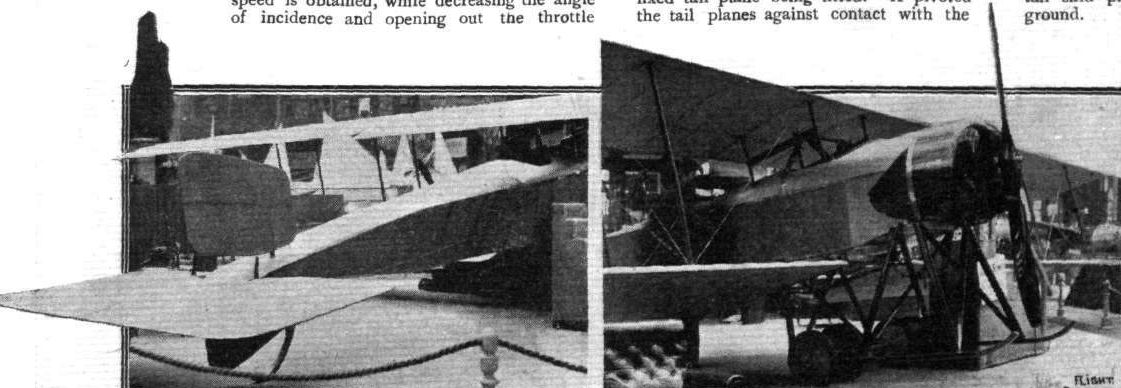
THE PAUL SCHMITT BIPLANE. - On the left are seen the tail planes.
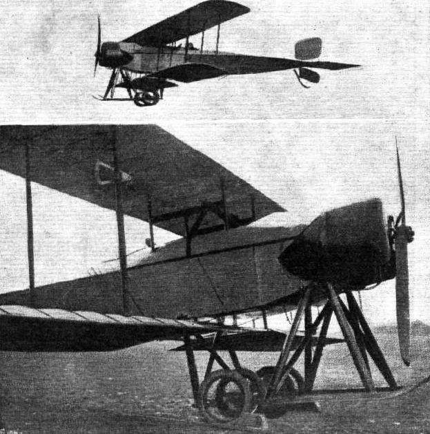
A view of the Paul Schmitt biplane in the air and of the chassis, &c.
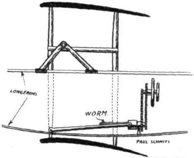
Diagrammatic sketch showing method of altering the angle of incidence in the Paul Schmitt biplane.
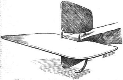
Tail planes of the Paul Schmitt biplane.
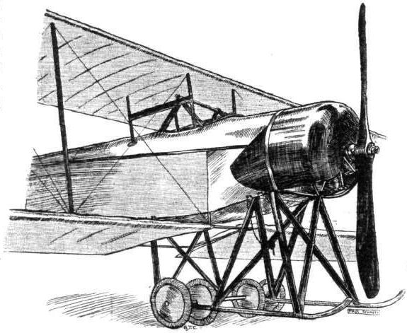
Sketch showing the very substantial chassis of the Paul Schmitt biplane.
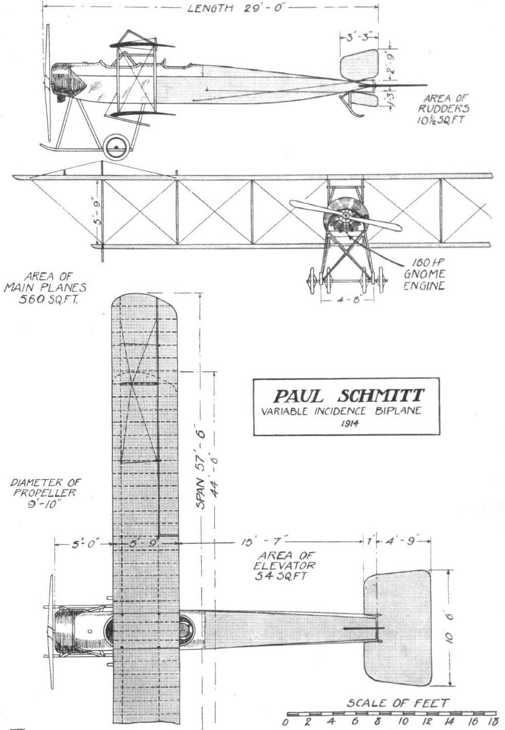
THE PAUL SCHMITT BIPLANE. - Plan, side and front elevations to scale.
Flight, June 5, 1914.
THE PRINCE HENRY CIRCUIT, 1914.
MACHINES IN PRINCE HENRY CIRCUIT.
The Sommer Arrow Biplane. - The German Sornmer Aircraft works have brought out a new Arrow type biplane for the Prince Henry Circuit. It is chiefly interesting on account of the fact that it is fitted with a rotary engine - a 100 h.p. Gnome - enclosed by an aluminium shield. In the bottom of this shield an opening has been cut in order to allow the exhaust gases to escape. In designing this machine, great attention has been paid to accessibility and ease of dismantling of the wings, an operation requiring only a few minutes' work.
Flight, September 18, 1914.
AIRCRAFT "MADE IN GERMANY"
WHICH MAY BE EMPLOYED AGAINST THE ALLIES.
33. The Sommer Arrow Biplane
differs somewhat from previous products of the German Sommer Aircraft Works, and was specially built for this year's Prince Henry Circuit. It is chiefly interesting on account of the fact that it is designed to take a rotary engine, a departure from usual German practice.
Aerodynamically this machine presents but little in the way of novelty, being characterised by the usual form of backswept wings, of which the upper plane is of slightly greater span than the lower one. The top plane is divided in the centre, where its two component parts are attached to a cabane of the monoplane type, formed by four steel tubes resting on the upper longerons of the fuselage. The lower plane is set at a small dihedral angle, and is attached by quick-release devices to the fuselage. In designing this machine great attention has been paid to accessibility and ease of dismantling, an operation requiring only a few minutes' work.
Mounted between double bearings in the nose of the fuselage is a 100 h.p. Gnome engine, covered in on the sides by an aluminium shield in the bottom of which openings have been cut out in order to allow exhaust gases to escape. Immediately behind the engine are the petrol and oil tanks. To the rear of them are the two seats, arranged tandem fashion, the pilot occupying the rear one, from where he has an unrestricted view in a downward direction.
The stern post of the fuselage, which takes the form of a steel tube, is continued upwards to act as a pivot for the balanced rudder. No fixed vertical tail fin is fitted. The horizontal stabilising plane is mounted on the gunwales of the fuselage, and has hinged to its trailing edge a divided elevator.
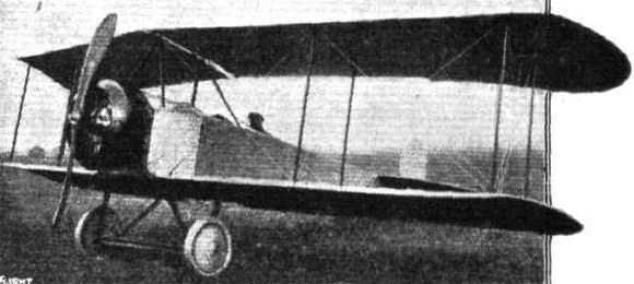
33. The Sommer biplane.
Flight, January 17, 1914.
FOREIGN AVIATION NEWS.
Gibert Lands on a Roof.
AFTER a long rest Gibert has returned to aviation, but his return was inauspicious. On the 8th, he went up at Issy on a Vendome monoplane, and on getting to a height of 500 metres flew round the Eiffel Tower. Soon after he commenced a vol plane, and seemingly miscalculated the rate of descent. When about thirty metres from the ground he switched on, but the motor refused to start, and the machine crashed on to the roof of a tile-works. Surprisingly little damage was done to roof and machine, whilst the pilot was unhurt.

Gibert's monoplane after his landing on the roof of some sheds near Paris. Note how, under the circumstances, comparatively little damage of any sort was done, either to the building or the machine.
Flight, January 10, 1914.
A NEW MILITARY VOISIN BIPLANE.
ONE of the Voisin machines recently turned out by this historic aeroplane factory possesses several very interesting features, as the accompanying sketch will show. Like most of the Voisin machines of recent years, it is constructed for the greater part of steel. It is a biplane of the "headless" type, and differs from previous models in the method of carrying the tail. Instead of the usual two pairs of triangular outriggers from the main planes, two single outriggers or tail booms are employed. Each of these is attached to the centre of one of the rear plane struts on either side of the nacelle, and extends rearwards horizontally, or parallel to the line of flight. These tail booms, therefore, offer considerably less resistance than the triangular arrangement. Both tail booms are strongly braced to the main planes, whilst the struts carrying the former are also strengthened by a pair of diagonal cross-struts to the corresponding fore-struts. The rear extremities of the tail booms carry a single elevator tailplane, which in turn carries two pairs of vertical rudders that move bodily with the elevator. Each pair of rudders is divided into two and arranged above and below the elevator. Mounted in the centre of the lower main plane is the nacelle, which extends well in front of the main planes. The pilot and passenger are seated in separate cockpits in front of the nacelle - the pilot being behind - whilst in the rear is mounted the engine, a 200 h.p. Clerget, which drives the propeller by means of chain gear. The nacelle is supported by a very simple sprung chassis, similar to those on other Voisin machines, and there is also a pair of wheels mounted on the nose of the nacelle. Ailerons are employed for lateral balance, and the main planes are set at a slight dihedral angle. The span of the machine is 15 m., and the weight of the machine ready for the air is 1,300 kilos.
"VEE JAY."
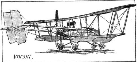
Flight, June 5, 1914.
EDDIES.
Building and flying an aeroplane out in South Africa is not exactly a Sunday school picnic, according to a letter I have received from Mr. A. K. Robertson, of Chiselhurst, Cambridge, Cape Province. Mr. Robertson's handiwork bears a slight resemblance to the Caudron biplane and took six months to build, only such materials as were unobtainable out there being imported. The work of construction was enlivened occasionally in the most unusual manners. Once, for instance, during a temporary suspension of operations, a family of rats was found comfortably installed in one of the extensions of the upper plane. On another occasion a swarm of bees took a fancy to the machine, much to the disgust of the erecters who did not relish the idea of working in a beehive, whilst it was an everyday occurrence for tarantulas to promenade up and down the ribs.
However, ultimately the machine was finished, and hauled down behind a motor car at night (to avoid the traffic) to the local racecourse. One fine morning, with a wind of only 10 m.p.h., the machine was tried, with the result shown in one of the accompanying photographs. Mr. Robertson, who had no previous experience in piloting an aeroplane, got into the seat, and a friend took hold of a wing tip while the engine was run throttled down. After deciding that everything was behaving "according to Cocker," Mr. Robertson nodded to his friend to let go, but the latter, not quite understanding the complexities of starting an aeroplane, "hung on like a true Briton," and did some giant leaps when the throttle was opened out. He was ultimately persuaded to let go, and after a run along the ground the machine was elevated a few feet and did a hop of about 400 yards. At this moment she was caught by a gust and raise to a height of about 50 ft. Before Mr. Robertson could get her nose down again she stalled and did a pancake from which there was no time to recover.
Mr. Robertson finishes his letter with the following brief but eloquent sentence: "I am rebuilding."
That's the right spirit. Stick to it, and better luck next time!
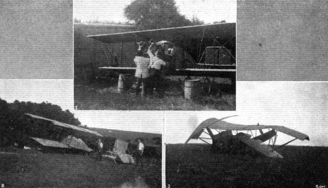
Mr. Robertson's home-made South African biplane. - 1. Mounting the 60 h.p. Anzani engine. 2. Before the smash, sheltering from the wind. 3. After the smash.