
Книги
Журнал
Flight за 1915 г.
356
Журнал - Flight за 1915 г.
Flight, October 15, 1915.
EDDIES.
From Mr. C. A. Wragg, hon. sec. of the Victoria Aero Club, Melbourne, the following interesting letter has arrived, relating how a few enthusiasts down that part of the world are "doing their bit" for the furtherance of aviation, albeit only in a small way yet:#
"The club was formed some twelve months ago by a few keen and kindred spirits, and has since been steadily growing. The meetings are held monthly, at which we generally manage to put in an interesting evening. At our next meeting a paper will be given by Mr. G. Hawker, on aero engines. We propose, as a club, to construct and experiment with gliders, to popularise gliding as a sport, to establish a library on the subject for the use of members, and, in fact, to do anything that will tend to promote interest in aviation. Very little can be done now, of course, because of the war; a number of the members have sailed with the Australian Flight for active service.
"Enclosed are photos of a few of the members with a glider, which was presented to the club by Dr. F. M. Johnson, who is now, we believe, in England. It had then no front elevator or vertical fin and was controlled by movements of the operator. It takes a good deal of wind to get it off, but is all the better for that in the air for a beginner, because of its inertia. We have been using it on a fairly steep slope and each operator, as he took the landing bump with set teeth, wished ardently for the power to increase the lift co-efficient if only for the last two seconds.
"We get just sufficient time in the air to make us hate the idea of coming to earth, and long to open a throttle and soar over the hills; it is tantalizing when we know the opportunities that exist in England and other countries for extended flights, but we get a lot of fun out of it, and some instruction; no doubt the time will soon be in Australia when aeroplanes in the air will be a common sight instead of one for all hands to stand and gaze at as at present.
"By the way, we've discovered a simple formula for the solution of flight problems; it is WPP2 # work multiplied by patience and perseverance squared.
"In closing, allow me to tender a personal appreciation of "FLIGHT"; to me it is a completely satisfying journal from "Eddies" chat to the articles contributed by the various scientists."
On behalf of "FLIGHT" I beg to thank Mr. Wragg for his good wishes, and will reciprocate by expressing the hope that he and his fellow workers will soon be fortunate enough to find a sportsman willing to furnish the means wherewith to put into effect a much simpler formula for the solution of flight problems, to wit # H.P.
"AEOLUS."
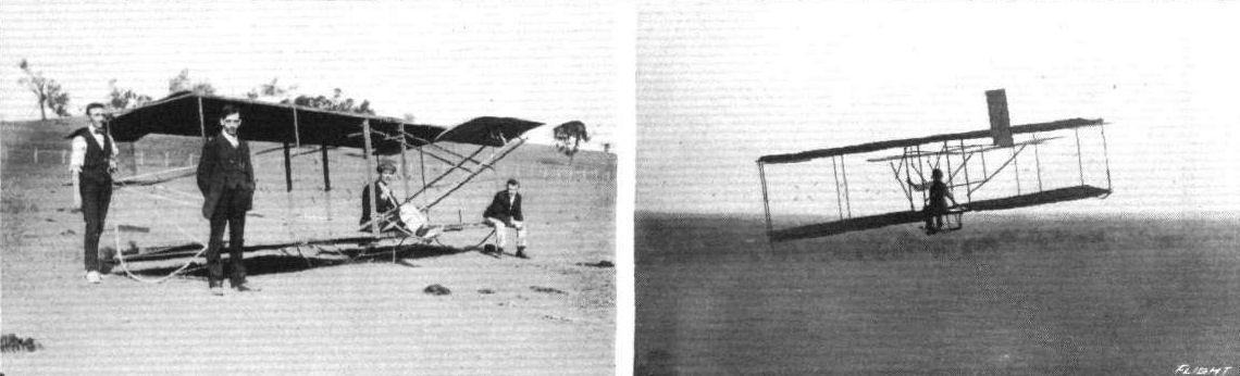
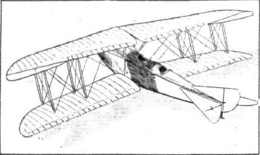
The glider and some of the members of the Victoria Aero Club, Melbourne. - On the right, the glider in flight.
Flight, July 23, 1915.
EDDIES.
Aviating under difficulties is an experience that most of the pioneers who have introduced the aeroplane to outof-the-way places may well have cause to remember, as I have no doubt such men as Mr. Delfosse Badgery and A. W. Jones would bear me out were they within speaking distance. It seems, however, that the success which has been the reward of these two pilots has encouraged others to face the difficulties, financial as well as geographical, of getting an aviation industry going in Australia. This emerges from a letter from a correspondent in Western Australia, in which he advises us that a new machine has just been completed by a small syndicate at Kalgoorlie. Few details are available yet beyond the fact that the machine is a tractor biplane with a span of - upper plane 34 ft., lower plane 30 ft., area 380 sq. ft., and a speed of about 50 m.p.h. The engine is a 50 h.p. Gnome. With the exception of the motor and the wire strainers every part of the machine has been locally made, and hence the claim of the constructors that this is the first aeroplane built in Australia by Australians and of Australian material.
* * *
The pilot of this new Australian machine is Mr. A. E. Geere, who will be remembered by many readers from his stay at Brooklands, where he took his "ticket" on a Vickers monoplane in, I think, September, 1912. After leaving the Vickers school Mr. Geere joined the Avro school at Shoreham in June, 1913, where he was manager and instructor until the school broke up.
* * *
The first flight of the new machine was from a point three miles east of Coolgardie to Kalgoorlie, where a landing was made in Bayley Street. A few days later, on June 10th to be exact, Mr. Geere attempted another trip from Coolgardie to Kalgoorlie. He had covered a distance of about eight miles when his engine began to show symptoms of lung trouble, which gradually grew worse until it coughed itself to a standstill. It was then that the first serious trouble began, for the ground below being not exactly like a billiard table, a forced landing had to be made at the first available spot, which proved to be a scrubby patch on which a flying squirrel might have made a successful landing, but not an aeroplane. However, everything considered, Mr. Geere was pretty lucky as the only damage done was a broken wing tip. A lorry was obtained on which the machine was loaded for transport back to Coolgardie, but whether it was because the horses saw a rival in the new-fangled thing on the lorry or simply from pure "cussedness," they bolted into the bush and banged the machine against the trees with such thoroughness that pretty bad damage accrued to the framework, putting it out of commission for some time. In no way disheartened, however, repairs are already well forward, and presently it is intended to make a flight from Coolgardie to Perth. Provided this is successful, it is on the cards it may help a long way towards selling one or more of the machines to the Commonwealth. One hopes that the initial hard luck will not pursue the machine in the future, and that the enthusiasts who built it may find the financial backing that will enable them to continue their good work.
Flight, August 13, 1915.
EDDIES.
Some time ago, it may be remembered, mention was made in "Eddies" of a new tractor biplane with a 50 horse-power Gnome engine built by a small syndicate out in Kalgoorlie, Australia, and which was, as stated at the time, badly damaged through the horses that were hauling it away on a lurry taking fright and bolting, as horses have a happy knack of doing at awkward moments. The Kalgoorlie Aero Syndicate, which is responsible for this aircraft, comprises ten working members, the majority of whom are artisans, and the whole of the machine, with the exception of the wire strainers, was built by themselves. It is expected that it will take a couple of months to put the machine in flying trim again, as most of the work is being done during spare hours. In spite of various handicaps, all the members are setting to work with a will, and are naturally enough looking forward to the time when their firstborn will again be ready to take the air. This is the sort of spirit which deserves and will without doubt be rewarded by ultimate success. One of the two accompanying photographs shows the machine where it had landed in Bayley Street, Coolgardie, after its first flight, and in the other it is seen standing on its nose after landing in the bush owing to engine trouble.
EDDIES.
Aviating under difficulties is an experience that most of the pioneers who have introduced the aeroplane to outof-the-way places may well have cause to remember, as I have no doubt such men as Mr. Delfosse Badgery and A. W. Jones would bear me out were they within speaking distance. It seems, however, that the success which has been the reward of these two pilots has encouraged others to face the difficulties, financial as well as geographical, of getting an aviation industry going in Australia. This emerges from a letter from a correspondent in Western Australia, in which he advises us that a new machine has just been completed by a small syndicate at Kalgoorlie. Few details are available yet beyond the fact that the machine is a tractor biplane with a span of - upper plane 34 ft., lower plane 30 ft., area 380 sq. ft., and a speed of about 50 m.p.h. The engine is a 50 h.p. Gnome. With the exception of the motor and the wire strainers every part of the machine has been locally made, and hence the claim of the constructors that this is the first aeroplane built in Australia by Australians and of Australian material.
* * *
The pilot of this new Australian machine is Mr. A. E. Geere, who will be remembered by many readers from his stay at Brooklands, where he took his "ticket" on a Vickers monoplane in, I think, September, 1912. After leaving the Vickers school Mr. Geere joined the Avro school at Shoreham in June, 1913, where he was manager and instructor until the school broke up.
* * *
The first flight of the new machine was from a point three miles east of Coolgardie to Kalgoorlie, where a landing was made in Bayley Street. A few days later, on June 10th to be exact, Mr. Geere attempted another trip from Coolgardie to Kalgoorlie. He had covered a distance of about eight miles when his engine began to show symptoms of lung trouble, which gradually grew worse until it coughed itself to a standstill. It was then that the first serious trouble began, for the ground below being not exactly like a billiard table, a forced landing had to be made at the first available spot, which proved to be a scrubby patch on which a flying squirrel might have made a successful landing, but not an aeroplane. However, everything considered, Mr. Geere was pretty lucky as the only damage done was a broken wing tip. A lorry was obtained on which the machine was loaded for transport back to Coolgardie, but whether it was because the horses saw a rival in the new-fangled thing on the lorry or simply from pure "cussedness," they bolted into the bush and banged the machine against the trees with such thoroughness that pretty bad damage accrued to the framework, putting it out of commission for some time. In no way disheartened, however, repairs are already well forward, and presently it is intended to make a flight from Coolgardie to Perth. Provided this is successful, it is on the cards it may help a long way towards selling one or more of the machines to the Commonwealth. One hopes that the initial hard luck will not pursue the machine in the future, and that the enthusiasts who built it may find the financial backing that will enable them to continue their good work.
Flight, August 13, 1915.
EDDIES.
Some time ago, it may be remembered, mention was made in "Eddies" of a new tractor biplane with a 50 horse-power Gnome engine built by a small syndicate out in Kalgoorlie, Australia, and which was, as stated at the time, badly damaged through the horses that were hauling it away on a lurry taking fright and bolting, as horses have a happy knack of doing at awkward moments. The Kalgoorlie Aero Syndicate, which is responsible for this aircraft, comprises ten working members, the majority of whom are artisans, and the whole of the machine, with the exception of the wire strainers, was built by themselves. It is expected that it will take a couple of months to put the machine in flying trim again, as most of the work is being done during spare hours. In spite of various handicaps, all the members are setting to work with a will, and are naturally enough looking forward to the time when their firstborn will again be ready to take the air. This is the sort of spirit which deserves and will without doubt be rewarded by ultimate success. One of the two accompanying photographs shows the machine where it had landed in Bayley Street, Coolgardie, after its first flight, and in the other it is seen standing on its nose after landing in the bush owing to engine trouble.

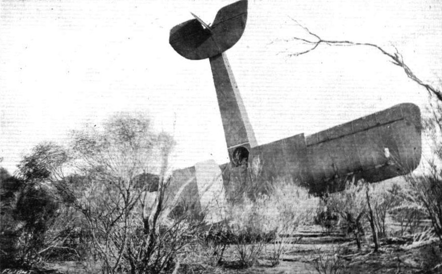
The Kalgoorlie Aero Syndicate's biplane on its nose in the bush after its forced landing through engine trouble.
Flight, February 12, 1915.
THE EVOLUTION OF THE ETRICH "TAUBE."
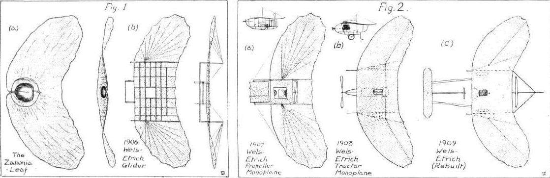
THE evolution of the Etrich "Taube" monoplane, a type upon which so many different makes of German machines are based, is not only of special interest just now on account of the prominence of the "Taube" in the daily events of the present war, but is in itself a particularly interesting subject from the historical point of view. "Taube," as, no doubt, most readers know, is simply the German for dove, and, as will be seen later, the different types of Etrich machines are designated by the names of various birds, owing to the fact that the planes are wing-shaped. As a matter of fact, this design does not derive its origin from the bird, but from the seed-leaf of the Zanonia palm, which possesses remarkable gliding properties when dried. From the sketch of this leaf (a), Fig. 1, it will be seen that the seed-pod has been provided by Nature with a perfect gliding mechanism in the shape of a crescent-shaped leaf. When the leaf dries the extremities curl both laterally and longitudinally, with the result that when the seed is ripe and falls from the tree, it makes a long stable glide to the ground. This fact was noted in a brochure written by Prof. Ahlborn, and it was this which first attracted the attention of Herr Igo Etrich, an Austrian, whose father, Herr Iganz Etrich, had started in 1898 to carry on the work of Otto Lilienthal, having bought the original gliders of that pioneer. A thorough study of the Zanonia leaf proved to be no easy matter owing to the difficulty first of obtaining specimens and then of observing the curves assumed by the leaf when gliding. However, a number of paper models were made, and the results obtained convinced Herr Etrich that in a machine constructed on these lines would be found the solution of the problem of making a flying machine automatically stable.
In conjunction with Franz Wels, he set to work, and a large glider, 12 m. span and weighing 20 kg., was built in 1904, the framework being bamboo. With a load of 25 kg., several hundred very successful glides were made, the apparatus showing a marked degree of stability. The success of these experiments induced Etrich and Wels to go astep further and endeavour to obtain prolonged horizontal flights. To this end they constructed another model, to which they fitted a 3 1/2 h.p. Laurin and Klement motor cycle engine. This machine had two ski-like skids, and was tested over snow, but the experiments met with little success, the machine never leaving the ground, owing, no doubt, to insufficient power and the incorrect location of line of thrust. The next move was to construct the large man-carrying glider (b) Fig. 1, and this was completed in 1906. It had an area of 35 sq. m., with a span of about 12m., and weighed, light, 164 kg. It was built up in three sections, the central section being supported on a skid under-carriage. In the centre, near the leading edge, an opening was cut in the plane for the pilot, who stood upright and held on to the cross beam in front of him. By swaying his body he could, to a certain extent, correct any rolling or pitching of the glider, caused by wind gusts, &c, but there was no other means of control. With 70 kg. sand ballast numerous successful glides were made, some about 300 m. in length, whilst equally encouraging glides were effected with Wels on board. On the 2nd of October, 1906, three flights of 150, 180 and 225 m. in length respectively were accomplished, the average height being about 10 m. Four more glides were made on October 8th. All these glides were started by running the glider on a small truck down an incline of 28 per cent., the glider "taking the air" when a certain speed was reached. When gliding the speed attained was from 13 to 15 m. per second, whilst the gliding angle was 7° or 8°.
<...>
THE EVOLUTION OF THE ETRICH "TAUBE."
THE evolution of the Etrich "Taube" monoplane, a type upon which so many different makes of German machines are based, is not only of special interest just now on account of the prominence of the "Taube" in the daily events of the present war, but is in itself a particularly interesting subject from the historical point of view. "Taube," as, no doubt, most readers know, is simply the German for dove, and, as will be seen later, the different types of Etrich machines are designated by the names of various birds, owing to the fact that the planes are wing-shaped. As a matter of fact, this design does not derive its origin from the bird, but from the seed-leaf of the Zanonia palm, which possesses remarkable gliding properties when dried. From the sketch of this leaf (a), Fig. 1, it will be seen that the seed-pod has been provided by Nature with a perfect gliding mechanism in the shape of a crescent-shaped leaf. When the leaf dries the extremities curl both laterally and longitudinally, with the result that when the seed is ripe and falls from the tree, it makes a long stable glide to the ground. This fact was noted in a brochure written by Prof. Ahlborn, and it was this which first attracted the attention of Herr Igo Etrich, an Austrian, whose father, Herr Iganz Etrich, had started in 1898 to carry on the work of Otto Lilienthal, having bought the original gliders of that pioneer. A thorough study of the Zanonia leaf proved to be no easy matter owing to the difficulty first of obtaining specimens and then of observing the curves assumed by the leaf when gliding. However, a number of paper models were made, and the results obtained convinced Herr Etrich that in a machine constructed on these lines would be found the solution of the problem of making a flying machine automatically stable.
In conjunction with Franz Wels, he set to work, and a large glider, 12 m. span and weighing 20 kg., was built in 1904, the framework being bamboo. With a load of 25 kg., several hundred very successful glides were made, the apparatus showing a marked degree of stability. The success of these experiments induced Etrich and Wels to go astep further and endeavour to obtain prolonged horizontal flights. To this end they constructed another model, to which they fitted a 3 1/2 h.p. Laurin and Klement motor cycle engine. This machine had two ski-like skids, and was tested over snow, but the experiments met with little success, the machine never leaving the ground, owing, no doubt, to insufficient power and the incorrect location of line of thrust. The next move was to construct the large man-carrying glider (b) Fig. 1, and this was completed in 1906. It had an area of 35 sq. m., with a span of about 12m., and weighed, light, 164 kg. It was built up in three sections, the central section being supported on a skid under-carriage. In the centre, near the leading edge, an opening was cut in the plane for the pilot, who stood upright and held on to the cross beam in front of him. By swaying his body he could, to a certain extent, correct any rolling or pitching of the glider, caused by wind gusts, &c, but there was no other means of control. With 70 kg. sand ballast numerous successful glides were made, some about 300 m. in length, whilst equally encouraging glides were effected with Wels on board. On the 2nd of October, 1906, three flights of 150, 180 and 225 m. in length respectively were accomplished, the average height being about 10 m. Four more glides were made on October 8th. All these glides were started by running the glider on a small truck down an incline of 28 per cent., the glider "taking the air" when a certain speed was reached. When gliding the speed attained was from 13 to 15 m. per second, whilst the gliding angle was 7° or 8°.
<...>
The evolution of the Etrich Taube.
Flight, February 12, 1915.
THE EVOLUTION OF THE ETRICH "TAUBE."
<...>
The experiments of Santos Dumont prompted Etrich to try once more power-driven flights, this time on a larger scale, so a 24 h.p. Antoinette engine was obtained and installed in the glider as shown in (b) Fig. 2. It will be seen that the planes still followed very closely the Zanonia leaf, but in order to effect better directional control a small elevator was fitted in front close up to the leading edge, whilst it was also possible to flex the wing tips. The engine was mounted below the plane in the under-carriage frame, and drove by means of a chain a crude form of variable-pitch propeller located slightly below, and almost in the centre of the plane, a portion of the latter being cut away so as to clear the propeller. The pilot was seated in much the same position as on the glider, and controlled the elevator by means of the pedal, the wing tips and the pitch of the propeller blades being operated by hand wheels. The under-carriage consisted of two solidly-built skids, and a pair of running wheels, supporting the plane about 1 m. above it by bamboo struts. This machine had a span of about 10 m., and an overall length of 5.4 m., the chord at the centre being 4.25 m. Etrich had originally intended fitting a 50 h.p. engine, but Wels favoured one of smaller horse-power, and persuaded him to fit the 24 h.p. engine. The ultimate trials, however, proved that this was by no means a powerful enough engine, and once again they failed to obtain extended flights. It is true that one or two hops were made, but these, it must be owned, were due to sudden wind gusts. However, they continued experimenting along these lines, making various alterations in design. For instance, the second trials, in 1908, were made with a tractor machine (b) Fig. 2. The Zanonia-form plane remained much the same, and the 24 h.p. Antoinette engine was still employed, but the whole machine was considerably lighter. The engine was mounted forward under the plane, and drove a tractor screw direct, whilst the pilot sat behind the engine, also under the plane. The under-carriage consisted of a simple framework to which was sprung, by means of full elliptic springs, a pair of running wheels. Behind the latter were two skids which prevented the machine from tilting over backwards. Although in some respects a distinct improvement on the previous model, this machine also was a failure, and did not appear to possess the stability of the original glider, whilst the advisability of fitting an elevator was also demonstrated. It was not until the next year, 1909, that Etrich, working on his own account - Wels having left him - achieved any notable success, making short flights on the old Wels-Etrich machine. He had made several alterations to this machine, (c) Fig. 2, notably the fitting of a front elevator, a rear vertical rudder, and a propeller mounted immediately behind the trailing edge. He also subsequently fitted an Anzani engine in place of the Antoinette. The first flight on this old machine was made on July 20th, when a distance of nearly 100 m. was flown, after which several other "hops" were accomplished from time to time until it "disintegrated" in September the same year.
<...>
The evolution of the Etrich Taube.
Flight, February 12, 1915.
THE EVOLUTION OF THE ETRICH "TAUBE."
<...>
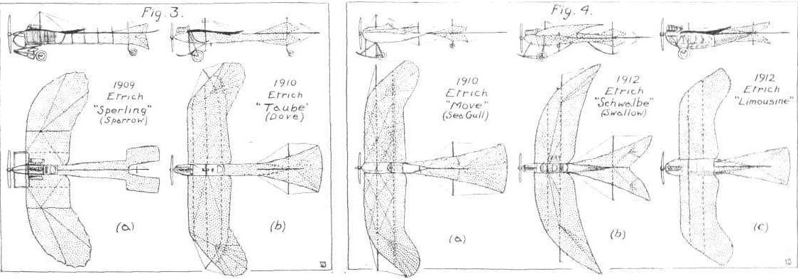
In the meanwhile, Etrich was engaged in the construction of an improved type of machine on the Zanonia principle, for although he had made the old machine fly there was a marked lack of the stability experienced with the glider. He was, however, convinced he was working in the right direction, and his new machine, completed in the summer of 1909, bore out his convictions during its ultimate trials. Etrich 1,"Sperling" or "Sparrow," (a) Fig. 3, embodied in a crude way the main characteristics of the present-day Taube - tractor screw, engine mounted right in front, modified Zanonia-form wings, and elevator-rudder-tail-planes mounted on a fuselage extending rearwards from the wings. The latter were not so crescent-shaped as those on the previous types, the leading edge being straight for more than one-third the span, the wing tips swept back and only slightly upturned. They were built up in three sections, and had a total area of 30 sq. m., the angle of incidence being 8°.
The tail consisted of a long narrow surface extending from the wings and branching into a fork at the rear, forming two rectangular surfaces. These acted as elevators, and were peculiar in that they were up-turned. In between the elevators was a vertical fan-shaped warping rudder. The whole of the tail was carried by a girder structure consisting of two longitudinals, one above the other. In its original form the undercarriage was a clumsy affair, as shown, but later a more efficient type was fitted, somewhat similar to that of the Bleriot. The engine, a 53 h.p. water-cooled Clerget, was mounted in the front of the rather wide body frame, with the radiators on either side. Behind the engine sat the pilot. On this machine Etrich put up several successful flights - real flights this time - ranging from 300 m. to 45 km. in length at a speed of about 70 kms. per hour. He found it very stable, and on several occasions flew without operating the control.
From the experience obtained with this machine Etrich, during the latter part of 1909, got out the design of a second machine, Etrich II, the "Taube" or "Dove," (b), Fig. 3, which was the first of numerous subsequent "Tauben " that differed but little from the Etrich II.
<...>
THE EVOLUTION OF THE ETRICH "TAUBE."
<...>
In the meanwhile, Etrich was engaged in the construction of an improved type of machine on the Zanonia principle, for although he had made the old machine fly there was a marked lack of the stability experienced with the glider. He was, however, convinced he was working in the right direction, and his new machine, completed in the summer of 1909, bore out his convictions during its ultimate trials. Etrich 1,"Sperling" or "Sparrow," (a) Fig. 3, embodied in a crude way the main characteristics of the present-day Taube - tractor screw, engine mounted right in front, modified Zanonia-form wings, and elevator-rudder-tail-planes mounted on a fuselage extending rearwards from the wings. The latter were not so crescent-shaped as those on the previous types, the leading edge being straight for more than one-third the span, the wing tips swept back and only slightly upturned. They were built up in three sections, and had a total area of 30 sq. m., the angle of incidence being 8°.
The tail consisted of a long narrow surface extending from the wings and branching into a fork at the rear, forming two rectangular surfaces. These acted as elevators, and were peculiar in that they were up-turned. In between the elevators was a vertical fan-shaped warping rudder. The whole of the tail was carried by a girder structure consisting of two longitudinals, one above the other. In its original form the undercarriage was a clumsy affair, as shown, but later a more efficient type was fitted, somewhat similar to that of the Bleriot. The engine, a 53 h.p. water-cooled Clerget, was mounted in the front of the rather wide body frame, with the radiators on either side. Behind the engine sat the pilot. On this machine Etrich put up several successful flights - real flights this time - ranging from 300 m. to 45 km. in length at a speed of about 70 kms. per hour. He found it very stable, and on several occasions flew without operating the control.
From the experience obtained with this machine Etrich, during the latter part of 1909, got out the design of a second machine, Etrich II, the "Taube" or "Dove," (b), Fig. 3, which was the first of numerous subsequent "Tauben " that differed but little from the Etrich II.
<...>
The evolution of the Etrich Taube.
Flight, February 12, 1915.
THE EVOLUTION OF THE ETRICH "TAUBE."
<...>
From the experience obtained with this machine Etrich, during the latter part of 1909, got out the design of a second machine, Etrich II, the "Taube" or "Dove," (b), Fig. 3, which was the first of numerous subsequent "Tauben " that differed but little from the Etrich II.
Illustrations of various Etrich monoplanes that have appeared in FLIGHT from time to time, show how the design remained practically the same throughout, the only differences being in dimensions and constructional details. Etrich II had a span of 14 m., a supporting surface of 32 sq. m., and an overall length of 10 m. The wings had a somewhat different shape to the predecessors, the leading edge being straight for nearly the whole span, and only the extremities swept back and up-turned. They were in two sections, one mounted on either side of a covered-in body, in the orthodox style, and cable braced from a central A mast on the body. Subsequently a girder understructure, extending from the body under the wings, was employed as an additional bracing, which formed a feature of nearly all Etrich machines until quite recently. The tail consisted of a horizontal fan-shaped surface, mounted on the top of the body, with a flexible trailing edge acting as an elevator. Above and below this were two diamond-shaped vertical surfaces, which acted as fins and rudders. The engine, a 50 h.p. Clerget, was mounted in the nose of the body, and drove a tractor screw direct, whilst the pilot sat in a cockpit behind. The original under-carriage was of the Bleriot type, with a central hockey-like skid. A large number of important flights were made on this machine - completed at the end of 1909 - with the result that several replicas were constructed.
The next machine to be built (in 1910), however, was more or less an experiment, and differed somewhat in construction. The main difference, as will be seen on referring to (a), Fig. 4, consisted of the short streamline body and the landing carriage. The former terminated just behind the wings, which had a similar plan-form as Etrich II, where the tail commenced - a similar practice to that followed just recently by Fokker on his monoplanes. The wings were braced to a central A mast and by four king posts, a wheel being fitted to the lower extremities of each outer king post. The under carriage consisted of a single central skid, behind which was sprung a wheel. The engine, a 60 h.p. Clerget, was mounted in the nose of the body, and the pilot sat behind. This machine had a span of 15 m., a supporting area of 32 sq. m., and a length of 10 m., its total weight, ready for the air, being 460 kgs. It had a speed of 80 kms. per hour.
<...>
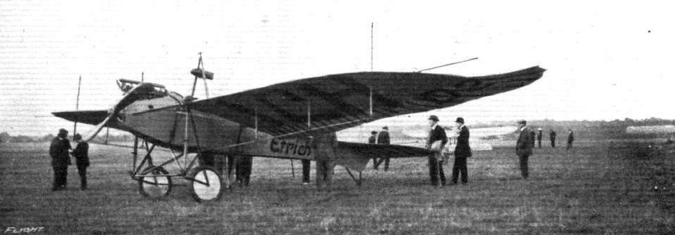
The 1913 Etrich Taube.
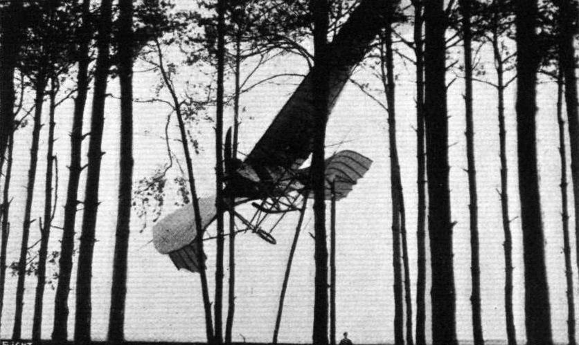
WINGED. - A German Taube in the tree tops.
The evolution of the Etrich Taube.
Flight, February 12, 1915.
THE EVOLUTION OF THE ETRICH "TAUBE."
<...>
Another machine, (c) Fig. 4, was a totally enclosed military monoplane built in 1912. The wings were of orthodox Etrich form, cable braced top and bottom, having a span of 12 m. The fish-shaped body was built up of wooden channel-section longitudinals, and wooden rings, covered with sheet aluminium from the nose to just behind the wings, and with fabric for the remainder. The wings were attached to the body high up, and the sides of the body underneath were cut so as to form windows. Inside the body were four seats, two pairs in tandem, the pilot being at the rear. The windows were of wire gauze and celluloid. A 60 h.p. Austro-Daimler engine was mounted high up in the nose of the body. The undercarriage consisted of a tubular axle and pair of wheels connected to the body by four tubular steel struts. Later this machine was altered, the seats were placed higher up, so that the pilot and passenger protruded above the body, whilst an additional wheel was mounted under the nose. Neither of these two machines showed to any particular advantage, and did not, therefore, form an important part of the Etrich programme.
<...>
The evolution of the Etrich Taube.
Flight, February 12, 1915.
THE EVOLUTION OF THE ETRICH "TAUBE."
<...>
Another experimental machine was the "Schwalbe" or "Swallow," (b) Fig. 4, built in 1912. The wings of this machine were almost true crescent-shape, the leading edge being curved from tip to tip. They were set at a dihedral angle and upturned at the tips, and the right-hand wing had a small window formed in it close to the body. The flexing elevator-tail was swallow-shape, and had the usual two diamond-shaped rudder-fins above and below it. The body, circular in section, was built up of tubular steel longitudinals and wooden rings, the whole being covered with fabric. In the nose of the body was the 60 h.p. engine, with the radiator immediately behind it. Behind this were three seats, one behind the other, the last being the pilot's. The control consisted of a vertical column and wheel, a backwards and forwards movement of the former operating the elevator, and a rotating of the latter actuating the rudders; no wing warping was employed, the flexibility of the wings alone being relied upon to maintain lateral stability. The chassis consisted of a central skid connected to the body by three pairs of V struts, and a sprung axle carrying a pair of wheels. The "Swallow," which was constructed mostly of steel, had a span of 13.25 m., an overall length of 87 m., weighed 45 kgs., and had a speed of 112 kms. per hour with three up.
<...>
The evolution of the Etrich Taube.
Flight, February 12, 1915.
THE EVOLUTION OF THE ETRICH "TAUBE."
<...>
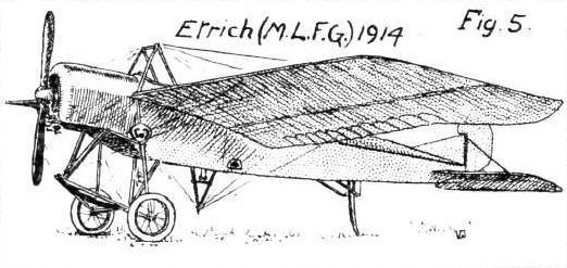
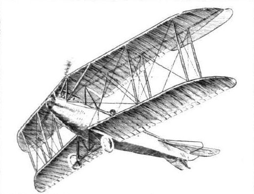
Fig. 5 shows the latest form of Etrich monoplane. The wings are of a modified Etrich form, with the tips only slightly swept back and upturned. They are cable braced in the orthodox monoplane style. The tail is of the hinged elevator type, with a partially balanced rudder and vertical fin above it. The body somewhat resembles that of the Morane-Saulnier, the pilot and passenger being similarly seated. The engine is an 80 h.p. Gnome, mounted in the nose of the body under a metal cowl. The under-carriage consists of a central short skid connected to the body by two pairs of V struts, and a divided axle, carrying a pair of wheels. The outer ends of the axle are connected to the body by two shock-absorbing rods.
<...>
THE EVOLUTION OF THE ETRICH "TAUBE."
<...>
Fig. 5 shows the latest form of Etrich monoplane. The wings are of a modified Etrich form, with the tips only slightly swept back and upturned. They are cable braced in the orthodox monoplane style. The tail is of the hinged elevator type, with a partially balanced rudder and vertical fin above it. The body somewhat resembles that of the Morane-Saulnier, the pilot and passenger being similarly seated. The engine is an 80 h.p. Gnome, mounted in the nose of the body under a metal cowl. The under-carriage consists of a central short skid connected to the body by two pairs of V struts, and a divided axle, carrying a pair of wheels. The outer ends of the axle are connected to the body by two shock-absorbing rods.
<...>
The evolution of the Etrich Taube.
Flight, May 14, 1915.
THE HUNGARIAN LLOYD BIPLANE.
COMPARATIVELY little had been heard of the Hungarian aeroplane industry until a short time before the outbreak of war, when, at the Aspern flying meeting, the Hungarian Lloyd firm leaped into prominence by the excellent performance of their new biplane. The first machine turned out by the Hungarian Lloyd Aeroplane and Motor Company, Ltd., of Aszod, Budapest, which was, by the way, built under licence from the German D.F.W. firm of Leipzig, was not finished until just before the Aspern meeting, being, in fact, put through her trial flights on the morning of June 21st, the first day of the meeting. The same evening Lieut. Bier, who will be remembered as the pilot of the Etrich monoplane in the first Circuit of Britain, and who is, or, at any rate, was, before the war, managing director of the Lloyd firm, took the machine up to an altitude of 4,120 metres with two passengers. This performance beat the record of 3,580 metres set up by Lieut, von Blaschke. On June 25th, he bettered Linnekogel's record for pilot and one passenger by reaching a height of 5,600 metres, and two days later improved his own record, pilot and one passenger, by 570 metres, and raised the record for pilot and two passengers to 4,440 metres. These performances came as a surprise to many, as the large biplane gave an impression of being rather heavy, almost clumsy, in fact. This impression, however, was not justified, as the weight empty of the Lloyd biplane is about 1,500 lbs., which cannot be considered unduly heavy in proportion to the size of the machine.
Being built under licence, it is only natural that the Lloyd biplane should follow closely the lines of its German prototype the D.F.W. biplane, of which latter various types have been described from time to time in FLIGHT. From an inspection of the accompanying illustrations it will be seen that the Lloyd model belongs to the "Pfeil" or arrow type, having its wings set at a backward slope of 8 degrees. In plan form the lower and upper planes differ considerably, the upper plane having a nearly straight trailing edge, whilst that of the lower plane is almost parallel to the leading edge. This arrangement would seem to be open to criticism from a constructional point of view, owing to the great amount of overhang of the inner portion of the trailing edge of the upper plane.
In addition to their rearward slope, the wings are staggered considerably in relation to one another, the upper one being about 2 ft. 6 ins. farther forward than the lower one. The top plane, which is divided in the centre, is attached to a steel tube cabane resting on the upper longitudinals of the body, whilst the two halves of the lower plane are attached to the sides of the fuselage. Two pairs of streamline struts connect the planes on each side of the body, and a peculiarity in the strutting is to be seen in the inner inter-plane struts, which do not, as is usually clone, run from upper to lower main plane, but from the spars of the top plane to the upper longitudinals of the body. Lateral control is by means of slightly upturned ailerons hinged to the top plane only.
The. fuselage, which is of rectangular section, is built up entirely of seamless steel tubes, oxy-acetylene welded. In the front portion it is covered with aluminium, and a turtle back of the same metal tops the body, while the rest of the fuselage is enclosed in a fabric covering. The engine - a 140 h.p. Hiero - is mounted on stout ash bearers, and is almost totally enclosed in the aluminium covering, which is at this point given a very good streamline form. The seats for pilot and observer are, as always in the arrow type of biplanes, placed comparatively far back in the fuselage, the pilot occupying the rear seat, where he is able to look straight down behind the trailing edge of the lower plane. The observer, on the other hand, is situated sufficiently far forward to look over the leading edge of the lower plane, although not far enough forward to be able to drop bombs over the edge of the plane. For bomb-dropping a special apparatus is fitted inside the fuselage. As in the D.F.W., the seating arrangement of the Lloyd biplane is most comfortable, and very complete instrument sets are fitted. The controls are of the usual type demanded by the German and Austro-Hungarian Governments, and consist of a rotatable hand wheel for warp and elevator and a foot bar for the rudder.
The under-carriage is of the simple "W" type, and is made of streamline steel tubes. The two halves of the divided axle are hinged to the apex of the inner chassis struts, and are sprung by rubber bands from the outer members of the chassis. Disc wheels are fitted in order to reduce head resistance. The tail planes consist of a triangular fixed plane, to which is hinged the divided elevator, and of a small vertical fin, to which is hinged the rudder. The speed range is from 35 to 80 m.p.h., and the machine has climbed the first 2,000 metres in 10 minutes.
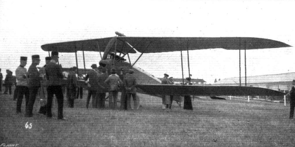
Three-quarter front view of the Lloyd biplane.
Three-quarter rear view, from above, of the Lloyd biplane.
The Lloyd biplane as seen from below.
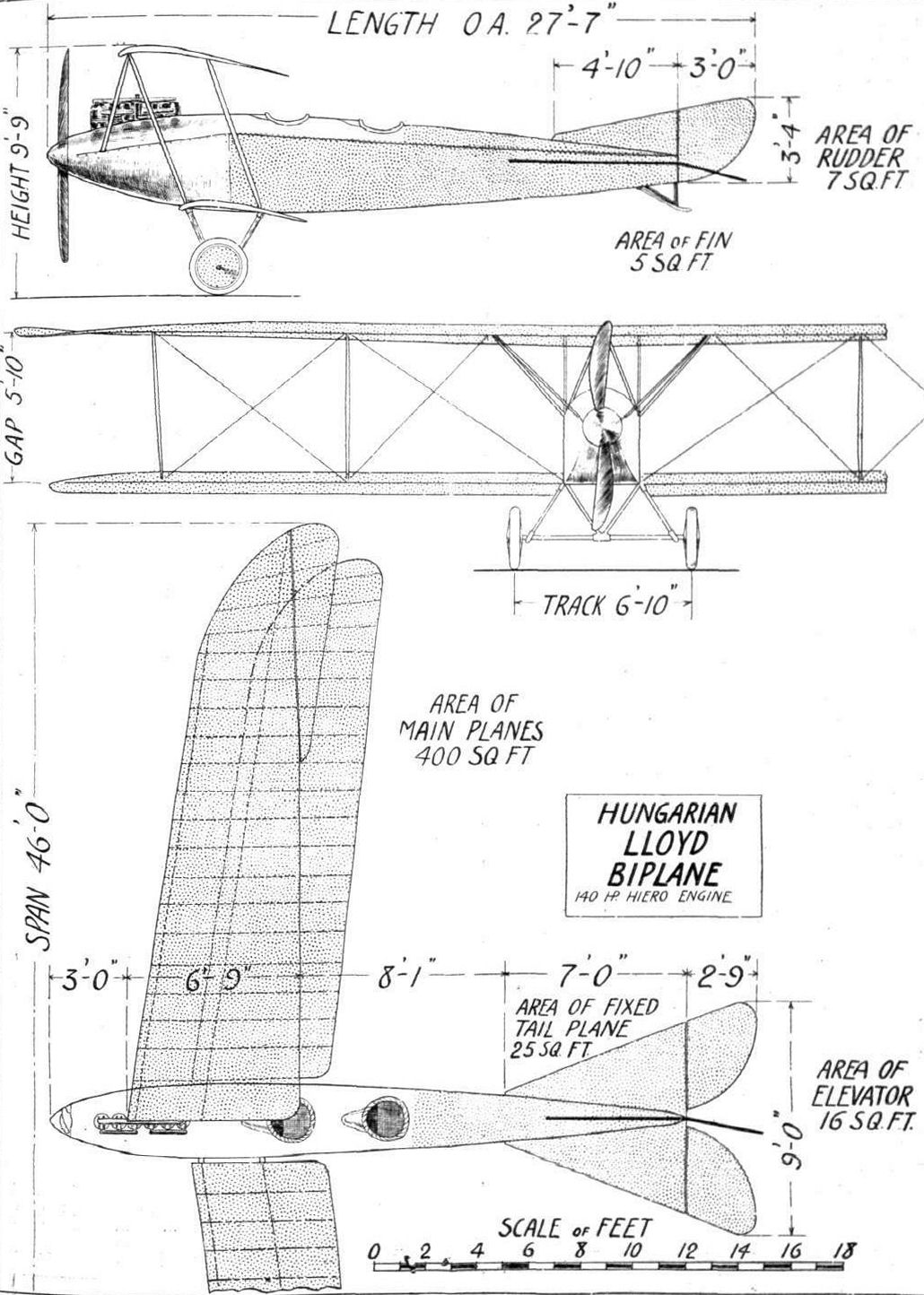
Plan, front and side elevation to scale of the Lloyd biplane.
Flight, January 8, 1915.
MILESTONES.
IN reviewing the long list of modern successful aeroplanes, it is a little surprising to discover how comparatively few can trace their ancestry back, through generation after generation, so to speak, to a prototype which, although perhaps appearing somewhat crude and incomplete in many ways, viewed in the light of present-day knowledge of aeroplane design, had embodied in it nearly all the fundamental ideas that have contributed towards the success attained by its present-day descendants. One reason for the absence of "pedigree" in a good many successful modern machines is, no doubt, that of the pioneers that helped to make history in the earlier days of aviation, comparatively few are still numbered among the leading constructors, and of these again several are now producing machines which, although being classed among the very best of the day, cannot, strictly speaking, be said to be direct descendants of the original type. Among the British designers whose products can justly lay claim to being "Thoroughbreds" must be mentioned in the very front rank the Avros, in which the fundamental idea underlying the design can be traced very clearly back to the old machine on which A. V. Roe did his first flights, which, although they may not have been more than glorified "hops," were nevertheless, even compared to up-to-date achievements, remarkable performances, when it is remembered that they were coaxed out of a machine fitted with an engine of what seems today ridiculously low power. That the modern Avros have proved and are proving so successful is one more proof, if such were needed, that Mr. Roe had already, in those "dark ages," a thorough grasp of his subject, and was sufficiently far-seeing to choose as subject for his experiments a type which was capable of development. The fact that he had to not only overcome aerodynamical difficulties, but also to fight against financial handicaps makes his ultimate success all the more creditable.
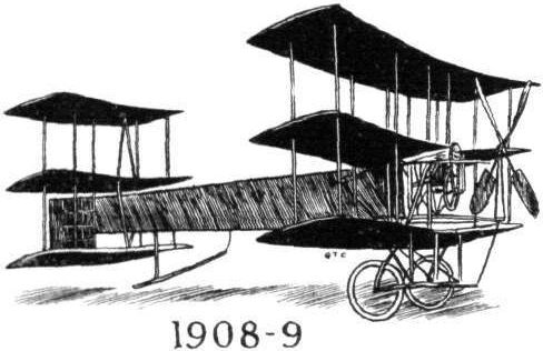
It was in the dark ages when the man who had the temerity to venture the opinion that it was possible for man to fly was regarded by the majority of people as a dreamer and a crank, not to say worse, that A. V. Roe began his experiments. Accounts of his trials and triumphs, as well as of his adversities, are to be found in the first numbers of FLIGHT, and before the foundation of this journal in our sister journal the Auto., and very interesting reading they make. The "Bull's Eye," or Roe 1 triplane, with which Mr. Roe carried out a number of experiments on Lea Marshes in 1908-09 was a very frail affair as will be gathered from the fact that it turned the scale at about 200 lbs. and had a surface of some 300 sq. ft. The body, which was triangular in section, was built up of longerons of deal, the whole being covered with cotton-oiled paper backed with muslin. The engine, a 10 (ten) h.p. Jap, was mounted in the nose of the body, and drove through a reduction gearing a four-bladed propeller. A two-bladed propeller was also tried, and the question of gear ratios, pitch, width of blades and diameter was made the subject of extensive tests, the results of which were carefully noted. The main planes, of which there were three, were swivelled round a horizontal axis, and were at the same time capable of being warped to maintain lateral stability. The triplane tail of the lifting type was rigidly attached to the rear end of the body, and steering up or down was effected by keeping the tail stationary whilst the main planes were swivelled around their axis in order to increase or decrease the angle of incidence. The warping of the main planes and the alteration of the angle of incidence were both effected by a single horizontal lever, whilst the vertical rudder at the rear of the tail planes provided horizontal directional control. The pilot was seated inside the triangular section body some distance behind the main planes, a position which proved very safe in the numerous accidents that were experienced. Several short flights were made on this machine in 1909, the two first of which ended in left hand side-slips, which were at the time thought to be due to the torque of the propeller, but were proved by later experience to be more probably caused by unskilful steering.
Several machines on similar lines were built, flown, damaged, rebuilt, flown, &c, during 1909-1910, in the course of which experiments the engine power was increased from 10 to 20 and 35 h.p. The next step in the development of the Avros was a new triplane that made its appearance in 1910. In this machine the span of the two upper planes was increased from 20 ft. to 31 ft., whilst that of the lower plane remained as before, 20 ft. The most important change in this machine in addition to the increase in span was the rigid attachment of the main planes to the body, and the substitution of ailerons for warping for lateral control. The triplane tail remained fixed, but steering up and down was effected by a rear elevator instead of by tilting the main planes. The engine fitted to this machine was a 35 h.p. Jap.
<...>
MILESTONES.
IN reviewing the long list of modern successful aeroplanes, it is a little surprising to discover how comparatively few can trace their ancestry back, through generation after generation, so to speak, to a prototype which, although perhaps appearing somewhat crude and incomplete in many ways, viewed in the light of present-day knowledge of aeroplane design, had embodied in it nearly all the fundamental ideas that have contributed towards the success attained by its present-day descendants. One reason for the absence of "pedigree" in a good many successful modern machines is, no doubt, that of the pioneers that helped to make history in the earlier days of aviation, comparatively few are still numbered among the leading constructors, and of these again several are now producing machines which, although being classed among the very best of the day, cannot, strictly speaking, be said to be direct descendants of the original type. Among the British designers whose products can justly lay claim to being "Thoroughbreds" must be mentioned in the very front rank the Avros, in which the fundamental idea underlying the design can be traced very clearly back to the old machine on which A. V. Roe did his first flights, which, although they may not have been more than glorified "hops," were nevertheless, even compared to up-to-date achievements, remarkable performances, when it is remembered that they were coaxed out of a machine fitted with an engine of what seems today ridiculously low power. That the modern Avros have proved and are proving so successful is one more proof, if such were needed, that Mr. Roe had already, in those "dark ages," a thorough grasp of his subject, and was sufficiently far-seeing to choose as subject for his experiments a type which was capable of development. The fact that he had to not only overcome aerodynamical difficulties, but also to fight against financial handicaps makes his ultimate success all the more creditable.
It was in the dark ages when the man who had the temerity to venture the opinion that it was possible for man to fly was regarded by the majority of people as a dreamer and a crank, not to say worse, that A. V. Roe began his experiments. Accounts of his trials and triumphs, as well as of his adversities, are to be found in the first numbers of FLIGHT, and before the foundation of this journal in our sister journal the Auto., and very interesting reading they make. The "Bull's Eye," or Roe 1 triplane, with which Mr. Roe carried out a number of experiments on Lea Marshes in 1908-09 was a very frail affair as will be gathered from the fact that it turned the scale at about 200 lbs. and had a surface of some 300 sq. ft. The body, which was triangular in section, was built up of longerons of deal, the whole being covered with cotton-oiled paper backed with muslin. The engine, a 10 (ten) h.p. Jap, was mounted in the nose of the body, and drove through a reduction gearing a four-bladed propeller. A two-bladed propeller was also tried, and the question of gear ratios, pitch, width of blades and diameter was made the subject of extensive tests, the results of which were carefully noted. The main planes, of which there were three, were swivelled round a horizontal axis, and were at the same time capable of being warped to maintain lateral stability. The triplane tail of the lifting type was rigidly attached to the rear end of the body, and steering up or down was effected by keeping the tail stationary whilst the main planes were swivelled around their axis in order to increase or decrease the angle of incidence. The warping of the main planes and the alteration of the angle of incidence were both effected by a single horizontal lever, whilst the vertical rudder at the rear of the tail planes provided horizontal directional control. The pilot was seated inside the triangular section body some distance behind the main planes, a position which proved very safe in the numerous accidents that were experienced. Several short flights were made on this machine in 1909, the two first of which ended in left hand side-slips, which were at the time thought to be due to the torque of the propeller, but were proved by later experience to be more probably caused by unskilful steering.
Several machines on similar lines were built, flown, damaged, rebuilt, flown, &c, during 1909-1910, in the course of which experiments the engine power was increased from 10 to 20 and 35 h.p. The next step in the development of the Avros was a new triplane that made its appearance in 1910. In this machine the span of the two upper planes was increased from 20 ft. to 31 ft., whilst that of the lower plane remained as before, 20 ft. The most important change in this machine in addition to the increase in span was the rigid attachment of the main planes to the body, and the substitution of ailerons for warping for lateral control. The triplane tail remained fixed, but steering up and down was effected by a rear elevator instead of by tilting the main planes. The engine fitted to this machine was a 35 h.p. Jap.
<...>
Flight, January 8, 1915.
MILESTONES.
IN reviewing the long list of modern successful aeroplanes, it is a little surprising to discover how comparatively few can trace their ancestry back, through generation after generation, so to speak, to a prototype which, although perhaps appearing somewhat crude and incomplete in many ways, viewed in the light of present-day knowledge of aeroplane design, had embodied in it nearly all the fundamental ideas that have contributed towards the success attained by its present-day descendants. One reason for the absence of "pedigree" in a good many successful modern machines is, no doubt, that of the pioneers that helped to make history in the earlier days of aviation, comparatively few are still numbered among the leading constructors, and of these again several are now producing machines which, although being classed among the very best of the day, cannot, strictly speaking, be said to be direct descendants of the original type. Among the British designers whose products can justly lay claim to being "Thoroughbreds" must be mentioned in the very front rank the Avros, in which the fundamental idea underlying the design can be traced very clearly back to the old machine on which A. V. Roe did his first flights, which, although they may not have been more than glorified "hops," were nevertheless, even compared to up-to-date achievements, remarkable performances, when it is remembered that they were coaxed out of a machine fitted with an engine of what seems today ridiculously low power. That the modern Avros have proved and are proving so successful is one more proof, if such were needed, that Mr. Roe had already, in those "dark ages," a thorough grasp of his subject, and was sufficiently far-seeing to choose as subject for his experiments a type which was capable of development. The fact that he had to not only overcome aerodynamical difficulties, but also to fight against financial handicaps makes his ultimate success all the more creditable.
It was in the dark ages when the man who had the temerity to venture the opinion that it was possible for man to fly was regarded by the majority of people as a dreamer and a crank, not to say worse, that A. V. Roe began his experiments. Accounts of his trials and triumphs, as well as of his adversities, are to be found in the first numbers of FLIGHT, and before the foundation of this journal in our sister journal the Auto., and very interesting reading they make. The "Bull's Eye," or Roe 1 triplane, with which Mr. Roe carried out a number of experiments on Lea Marshes in 1908-09 was a very frail affair as will be gathered from the fact that it turned the scale at about 200 lbs. and had a surface of some 300 sq. ft. The body, which was triangular in section, was built up of longerons of deal, the whole being covered with cotton-oiled paper backed with muslin. The engine, a 10 (ten) h.p. Jap, was mounted in the nose of the body, and drove through a reduction gearing a four-bladed propeller. A two-bladed propeller was also tried, and the question of gear ratios, pitch, width of blades and diameter was made the subject of extensive tests, the results of which were carefully noted. The main planes, of which there were three, were swivelled round a horizontal axis, and were at the same time capable of being warped to maintain lateral stability. The triplane tail of the lifting type was rigidly attached to the rear end of the body, and steering up or down was effected by keeping the tail stationary whilst the main planes were swivelled around their axis in order to increase or decrease the angle of incidence. The warping of the main planes and the alteration of the angle of incidence were both effected by a single horizontal lever, whilst the vertical rudder at the rear of the tail planes provided horizontal directional control. The pilot was seated inside the triangular section body some distance behind the main planes, a position which proved very safe in the numerous accidents that were experienced. Several short flights were made on this machine in 1909, the two first of which ended in left hand side-slips, which were at the time thought to be due to the torque of the propeller, but were proved by later experience to be more probably caused by unskilful steering.
Several machines on similar lines were built, flown, damaged, rebuilt, flown, &c, during 1909-1910, in the course of which experiments the engine power was increased from 10 to 20 and 35 h.p. The next step in the development of the Avros was a new triplane that made its appearance in 1910. In this machine the span of the two upper planes was increased from 20 ft. to 31 ft., whilst that of the lower plane remained as before, 20 ft. The most important change in this machine in addition to the increase in span was the rigid attachment of the main planes to the body, and the substitution of ailerons for warping for lateral control. The triplane tail remained fixed, but steering up and down was effected by a rear elevator instead of by tilting the main planes. The engine fitted to this machine was a 35 h.p. Jap.
<...>
Flight, January 8, 1915.
MILESTONES.
<...>
In the same year (1910), about a month later, another triplane made its appearance. In this several innovations were to be found, most notable among which was the fitting of a monoplane non-lifting tail instead of the weight-carrying triplane tail with which all previous Avros had been fitted. Another improvement was effected in the arrangements of the controls, which were in this machine made more to conform with standard practice in that the warp and elevator were operated by a hand-wheel mounted on a single central vertical column, a to-and-fro movement of which actuated the elevator, whilst rotation of the hand-wheel operated the warp. A pivoted foot-bar controlled the single rudder working in the opening between the two parts of the divided rear elevator. A Green engine of 35 h.p. was built into the nose of the body, and the radiator mounted between the two inner inter-plane struts above the centre plane. A considerable amount of flying was done on this machine before it was ultimately superseded by the graceful little biplane which even today would compare favourably with modern machines of the same horse-power.
<...>
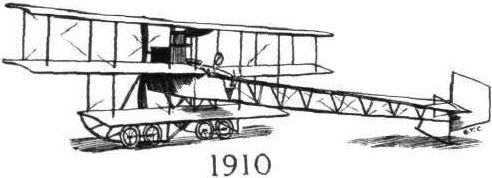
Flight, January 8, 1915.
MILESTONES.
<...>
It was in 1911 that the Avro biplane first came into being, and it soon became a very popular machine among Milestones the Brooklands' pilots, some of whom, notably Pixton and Raynham, made some excellent flights on it in all sorts of weather, thus proving its airworthiness. The body of the biplane was of similar construction to that of the triplanes, that is to say, it was of triangular section built up of longitudinals connected by struts and wired diagonally. Only the nose of the body was covered in by fabric up to a point near the pilot's seat, the rear portion of it being left open. In the nose of the body, mounted on stout bearers, was the engine, a 35 h.p. Green. Pilot's and passenger's seats were arranged tandem fashion, the pilot occupying the rear seat just behind the trailing edge of the main planes.
The chassis was of the wheel and skid type, the latter projecting some distance out in front of the propeller, so as to protect this vulnerable member from damage in case of a rough landing. The tail planes consisted of a flat, non-lifting stabilising plane, to the trailing edge of which was hinged the divided elevator. The stern post of the body was extended up and down to form a pivot for the rudder, which worked in the opening between the two parts of the elevator. Control was by means of a single column surmounted by a hand-wheel, and a foot-bar operated the rudder. Lateral stability was maintained by warping the main planes, the rear spars being hinged at the end sections to avoid bending the spars, which were thus left rigid in the centre portion, whilst in the end sections they moved helically. The main planes were made in sections easily detachable, in order to facilitate transport and storage. One of the best flights made on this machine was a cross-country trip from Brooklands to Brighton made by Mr. Pixton.
<...>

TUITION BY MOONLIGHT. - From the original drawing by C. Fleming Williams. This charming picture depicts Mr. Rowland Ding of the Seaplane School, Windermere, giving lessons by moonlight over Lake Windermere - work unique to this special school.

Flight, January 8, 1915.
MILESTONES.
<...>
The next step in the evolution of the Avro biplane was another tractor biplane in which numerous alterations as regards component parts were carried out, but which was fundamentally a logical development of the machine already described. With a view to provide more comfort for the pilot than was afforded by the comparatively shallow body of the Green-engined biplane, the fuselage of the next one in the series was made of rectangular section and was very deep so as to leave only the pilot's head projecting above the top covering. As regards the main planes and tail planes no radical alterations were made, but the under-carriage, which was hitherto of the wheel and skid type, was superseded by one resembling that of the Nieuport monoplanes. A short central skid was carried on three pairs of V-struts, and served as an anchorage for the leaf spring axle that formed the shock-absorbing device. The great amount of flexibility of this type of under-carriage caused considerable controversy, some critics maintaining that it was too "squashy" to stand up to its work, others being of opinion that its flexibility was just its greatest advantage, as it saved the remainder of the machine from receiving any severe shocks in case of a rough landing. Passenger's and pilot's seats were arranged as before in tandem, with the passenger in front. The engine fitted was a 60 h.p. E.N.V.
<...>
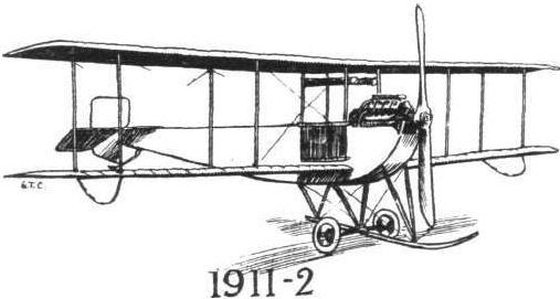
Flight, January 8, 1915.
MILESTONES.
<...>
Then followed, in 1912, a very similar biplane in which, however, the body had been made considerably wider, thus giving more elbow room for the occupants, but otherwise following the practice of the previous model. This type was fitted with a 50 h.p. Gnome engine, and a great number of the 50 h.p. type were sold to the Government and proved very successful.
<...>
Flight, October 29, 1915.
CONSTRUCTIONAL DETAILS.-VIII.
<...>
In the double skid type of chassis illustrated in our last issue the suspension is generally fairly simple, since it is possible to sling the wheel axle by means of strands of rubber from the two skids. When a single, central skid is employed it is no longer possible to solve the problem of elastic suspension quite so simply. There are, however, two or three alternative ways of providing the necessary flexibility. One of these is to make the axle itself flexible. This is generally obtained either by building up the axle in the form of a transverse laminated steel spring which carries on its extremities the two wheels, or by mounting the wheels on two short stub axles, which are then in turn connected at their outer ends to a transverse spring mounted immediately above the axles. In one of the accompanying pages of illustrations will be found two examples of the transverse laminated spring axle. One is the French Nieuport monoplane, and the other the older type Avro biplane. These two undercarriages are similar in type, but differ somewhat in detail. The construction will, we think, be clear from the sketches without needing any explanation, except that in both cases the chassis struts are streamline steel tubes. In the Nieuport the central skid is a steel tube, whereas in the Avro this member is made of ash.
<...>

A PEACEFUL EVENING BEFORE THE WAR. - Another beautiful sunset at Hendon, with an Avro passing at speed.
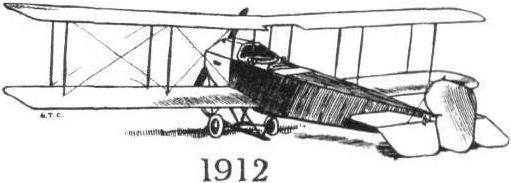
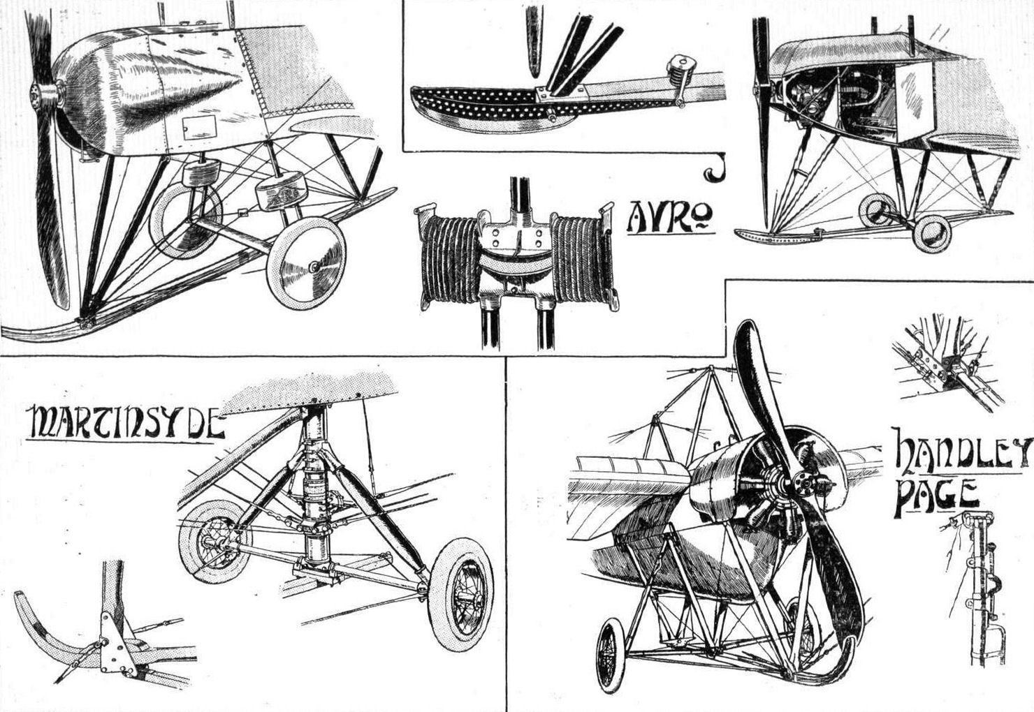
Various types of single-skid undercarriages.
Flight, January 8, 1915.
MILESTONES.
<...>
Finally followed, in 1913, the latest type Avro biplane, which has proved by far the most generally successful of all the machines produced by this enterprising firm. In the latest type, the body has been redesigned, and, while retaining its rectangular section, is of a much more pleasing outline, as well as being possibly of a better streamline form. The main planes, which possess all the characteristics of the previous models as regards their plan form, are staggered, and the chassis, although being of a different form from that of the 50 h.p. type, is as flexible as was the old one and a more satisfactory proposition from a practical point of view, having telescopic tubes and rubber shock-absorbers.
This, briefly, is, then, the history of the evolution of the Avro machines. True, Mr. Roe has produced other types, such as the enclosed monoplane, the all-enclosed biplane (which was never seriously considered by the authorities, although quite probably having in it the germ of the machine of the future), the "pusher" biplane exhibited at the last Olympia aero show, the small "arrow" type scouting biplane, and one or two others, but they are not, strictly speaking, part of the development of the Avros, being more to be considered as a side issue.
What the next type of Avro will be like is a matter for conjecture, but one can safely trust the versatile designer to produce something that will be as far ahead of the present machine as that was ahead of the one preceding it. Probably Messrs. A. V. Roe and Co. are too busy at present turning out their standard type to find the time for experimenting with new designs or testing developments, but when the war is over we may expect to see new models emanate from the busy Manchester works.
Flight, October 29, 1915.
CONSTRUCTIONAL DETAILS.-VIII.
<...>
In the double skid type of chassis illustrated in our last issue the suspension is generally fairly simple, since it is possible to sling the wheel axle by means of strands of rubber from the two skids. When a single, central skid is employed it is no longer possible to solve the problem of elastic suspension quite so simply. There are, however, two or three alternative ways of providing the necessary flexibility. One of these is to make the axle itself flexible. This is generally obtained either by building up the axle in the form of a transverse laminated steel spring which carries on its extremities the two wheels, or by mounting the wheels on two short stub axles, which are then in turn connected at their outer ends to a transverse spring mounted immediately above the axles. In one of the accompanying pages of illustrations will be found two examples of the transverse laminated spring axle. One is the French Nieuport monoplane, and the other the older type Avro biplane. These two undercarriages are similar in type, but differ somewhat in detail. The construction will, we think, be clear from the sketches without needing any explanation, except that in both cases the chassis struts are streamline steel tubes. In the Nieuport the central skid is a steel tube, whereas in the Avro this member is made of ash.
<...>
When the shock absorbers take the form of rubber cord, several types are, of course, available. Two of these have been shown in the accompanying sketches. In the later Avro biplanes the members running from the axle to the body are three in number on each side. Two run from the axle to the shock absorbers, and one from the body to the shock absorbers. The two lower tubes carry on their upper ends a cross-piece, and a similar cross-piece is secured to the lower end of the upper single tube. The latter passes through an opening in the "Tee" piece of the two lower tubes, and rubber cords wrapped around the cross-pieces provide the springing. A rubber pad or cushion is interposed between the cross-pieces, and serves to take care of the shocks due to rebound.
<...>
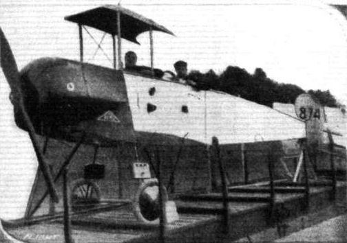
WOUNDED FLYER. - Squadron-Commander Briggs' Avro biplane, captured by the Germans at Friedrichshafen. Note the bullet holes In the fuselage.
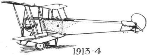
Various types of single-skid undercarriages.
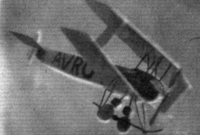
SCALE MODEL. - An Avro scout made by Mr. S. Benington-Stoner.
Flight, November 5, 1915.
EDDIES.
One of the latest additions to the fleet of the N.A.C. on Lake Windermere is a Blackburn monoplane with a 100 h.p. Anzani engine. In its general arrangement this machine is, as will be seen from the accompanying photograph, similar to the monoplane exhibited at the last Olympia Aero Show. The nose of the body is somewhat different, however, owing to the fitting of an Anzani engine instead of the Gnome used on the Show 'bus. The change from a land machine to a waterplane has been effected without any great alterations, the wheels and their axles being removed and two cross members substituted, from which the two floats are sprung by rubber bands. This machine arrived the other day, and was immediately erected. As soon as this was accomplished, Mr. Ding took it out for a trial run, and found it in perfect trim, needing no adjustments whatever. Another proof of Blackburn efficiency and thoroughness.
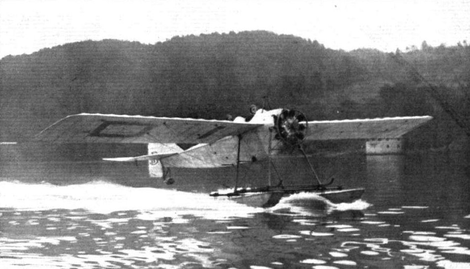
"OFF FOR A SPIN." - The 100 h.p. Anzani-englned Blackburn monoplane of the Northern Aircraft Co. starting on a trip over Lake Windermere, with Mr. Rowland Ding at the helm and Lieut. Stubbs in the passenger's seat. October 1915.

AT THE N.A.C. SCHOOL ON LAKE WINDERMERE. - Two of the machines in use for pupils. Left: The N.A.C. 80 h.p. Gnome biplane just "off"; and, in the foreground, the 100 h.p. Anzani-Blackburn monoplane.
Flight, October 22, 1915.
CONSTRUCTIONAL DETAILS.-VII.
<...>
Yet another form of undercarriage having double skids is shown in the sketch of the Coanda-Bristol biplane. Here the two skids are carried in the usual way on four struts coming down from the body, and a single axle carries the two main alighting wheels. There is, however, another pair of smaller wheels mounted on an axle slung by rubber bands from a forward projection of the skids. The purpose of these front wheels is, of course, to prevent the machine from turning up on its nose when landing on rough ground.
<...>
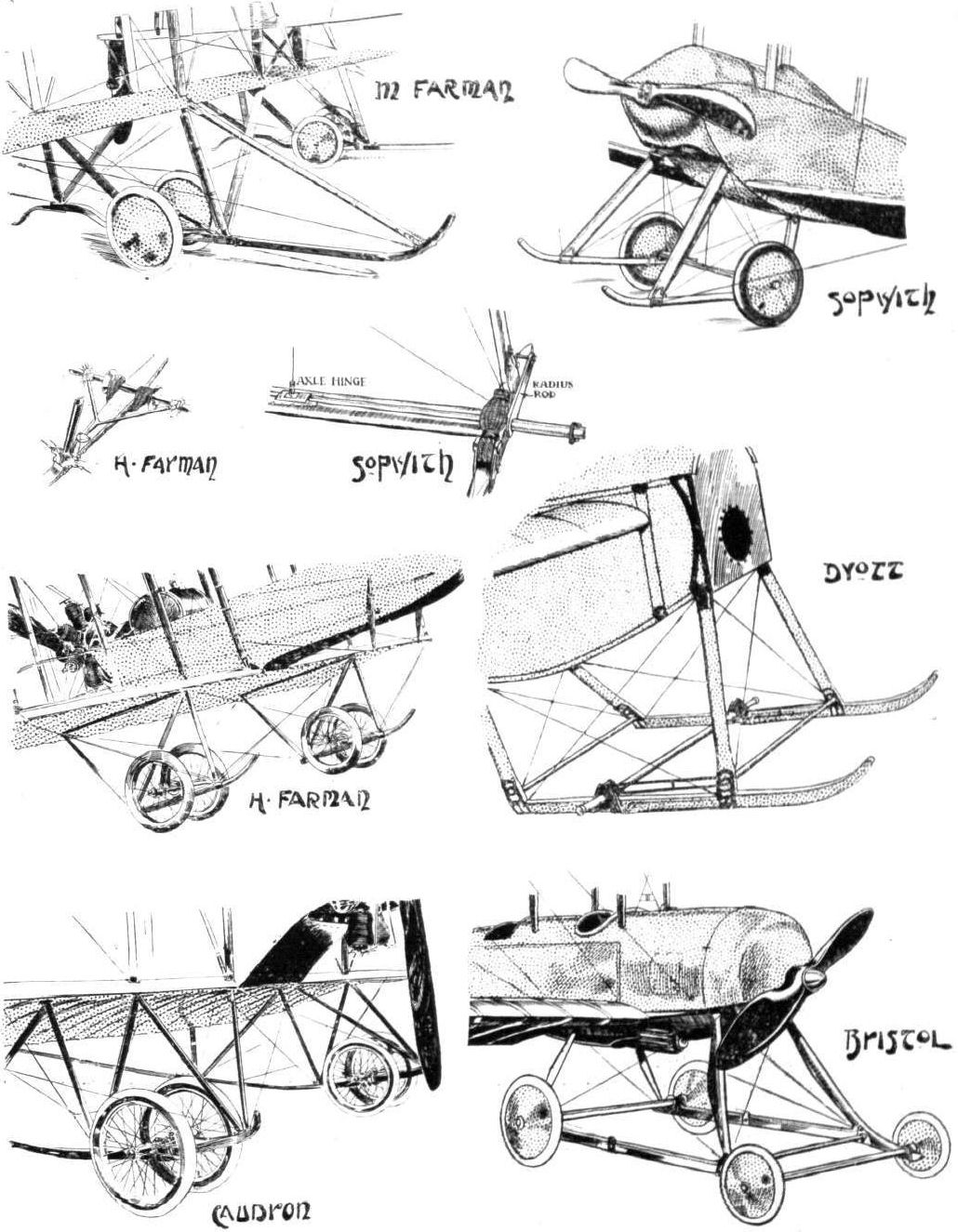
Various types of double skid undercarriages.
Flight, March 26, 1915.
EDDIES.
Although accounts of duels in the air are frequent enough in the daily press, these reports are generally more or less coloured, and frequently sound highly improbable. I was therefore very interested the other day in hearing from a pilot who was home on leave a description of a fight between an English and a German machine. My informant was stationed at - well, never mind, "somewhere in France" - when one day a German machine having slightly backswept wings (probably an Aviatik biplane) appeared over the town flying at a great height, and dropped three bombs in quick succession. After this heroic feat, the machine turned tail and headed towards the German lines. Two Bristol scouts were quickly away in pursuit, one of which returned after about an hour's absence, the pilot having been unable to find his quarry. Everybody was scanning the skies anxiously awaiting the return of the second Bristol when suddenly the Aviatik hove in sight again, probably, my informant thinks, to try to find out what damage his bombs had done. Presently the second Bristol scout was seen some little distance behind the Aviatik, going - in the fluent flow of the story I did not quite catch the words used by my informant, but it was something to do with leather, and intended to convey the impression that the Bristol was not actually crawling along. It did not take the British 'bus long to overhaul the Aviatik, and as he flew past it, reports could be distinctly heard from the rifles which had been strapped on each side of the fuselage. Getting a short distance ahead of the German biplane, the Bristol was seen to swerve sharply and fly right across its course, evidently trying to head the German off. This performance was repeated several times, the Bristol crossing the nose of the Aviatik at very close quarters. Suddenly the Aviatik was seen to put its nose down, and presently flames were visible behind the engine, the machine falling to the ground a blazing wreck. The officer piloting the Bristol returned shortly afterwards, and was, needless to say, received with enthusiasm.
Flight, November 12, 1915.
CONSTRUCTIONAL DETAILS.-X.
UNDERCARRIAGES of the "Vee" type and constructed of steel tubes were dealt with in our last issue, and some of the relative advantages of the two forms of construction, steel and wood, were pointed out. In our present page of illustrations are shown a few examples of how the construction of a "Vee" undercarriage may be carried out when the material employed is wood. A very simple type of chassis, offering a minimum of head resistance, is that of the Bristol scouting biplane, the first of which was exhibited, as our readers will remember, at the Olympia Aero Show in 1914. A good deal of criticism of this chassis was vouchsafed at the time from various quarters, mainly on the grounds that spruce struts had been used, and that the rear struts were much more nearly vertical than is usual practice. Since then, however, Bristol scouts have done some exceedingly good work, and as far as one can gather, the undercarriage has, without being materially altered, proved equal to the work for which it was designed. The four struts that constitute the chassis are secured at the top to the lower longitudinals of the body by steel clips, and are joined together two and two at their lower ends by other steel clips bolted through the lower, flat portion of the struts. From these clips project outwards on each side short lugs, to which are anchored the rubber cords that provide the flexible suspension of the wheels.
The single tubular axle rests in the angle between the struts, and is prevented from moving sideways by steel wires running from the rear chassis strut on one side to the opposite end of the axle. No radius rods are fitted, the rear struts being so nearly vertical that they prevent the axle from moving back to any appreciable extent.
<...>
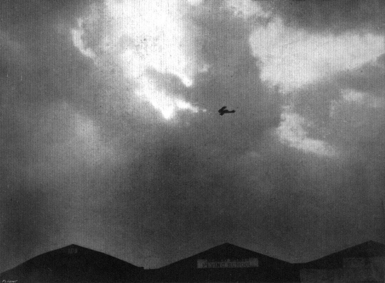
A reminiscence of Flight-Commander S. V. Sippe, D.S.O. (whose marriage was announced on December 8th), on the Bristol scout at Brooklands Aerodrome in the days that are gone.


Various "Vee"-type undercarriages constructed of wood.
Flight, December 3, 1915.
AN ORIGINAL IRISH MONOPLANE.
IN these days when the tendency is everywhere towards standardisation it is quite refreshing to be reminded that, great as have been the results achieved with types of wing sections that do not differ greatly among themselves, there are people who do not entirely agree that development is travelling entirely along the right track. One of those, who not only offers this negative criticism but who is of the opinion that he has found a better form of wing, is Mr. J. Cordner, of John Street, Londonderry, who has for a number of years been working upon lines of his own, attacking the problem, rightly or wrongly, in an entirely different way from what has come to be considered orthodox. Mr. Cordner informs us that his machine has done several short flights, during which, he says, the machine was found to possess a very good speed range, leaving the ground at something like 15 m.p.h., while the maximum speed, he states, is very high, how high we are not in a position to say. She also appears, from the short flights possible in the restricted ground available, to have a reasonably good climbing power.
In its present form the Cordner monoplane is the result of years of experiments, first with models and later with full size machines to which reference in the past has been made in "FLIGHT." As experience dictated these were altered and improved, the earlier ones having a tail of similar construction to that of the main planes and an open fuselage. Later on the body was covered in in order to improve the speed. A form of aileron was employed for steering, no vertical rudder being fitted. Engines of various types and h.p. were tried, and the undercarriage redesigned time after time. "Straights" were made, mere hops it is true, but the machine got off the ground. Then turns were attempted and, according to Mr. Cordner, with good results.
In its present form the Cordner monoplane may be said to represent a concession to orthodoxy as far as the body, tail and undercarriage are concerned, but the peculiar wing construction has been retained. Various materials have been tried, the wings having at various times been built up of three-ply wood, covering and all, and at other times a skeleton framework covered with fabric has formed the lifting surfaces. However, in general principle the form of the wings, if not the construction, has been retained.
It is a little difficult to explain the arrangement in words, but the accompanying sketch will, we think, make it perfectly clear. As to the action of this peculiar wing form one cannot always follow the inventor in his claims that it obtains a better "grip" on the air, gives less resistance, more area and better speed range. As regards the first claim. By grip we take it that the inventor means to indicate that the suction on the upper surface of the wing and the pressure on the lower surface are greater than can be obtained with the ordinary form of wing section. With regard to the upper surface it would appear to us that the region of rarified air or "partial vacuum" above the plane would be filled up by the air rushing through the triangular openings below the plane, and that therefore the resulting lift would be reduced. Again, the lower surface may be said to consist of a series of alternate dihedral surfaces tapering towards the rear and negatively dihedral surfaces flattening out towards the rear, which, although certainly presenting a greater surface, would also seem to offer more resistance. If the maximum speed can be attained we quite agree that it should be possible to bring the minimum speed down to a very low figure, especially as the ailerons, if pulled down simultaneously, will, by closing some of the pockets in the rear portion of the wing, act as a very powerful brake. That, as Mr. Cordner claims, the danger of "side slipping" is greatly reduced, if not altogether eliminated, seems reasonable enough in view of the great amount of more or less vertical surface presented by the pockets of the wings. Whatever one's opinion of the merits of this original wing form, it certainly should be given a thorough trial in practice, as for instance by building a pair of wings of the same span and chord as those of some well-known machine when the results could be directly compared.
Regarding the rest of the machine the Cordner monoplane presents nothing startling in the way of deviations from ordinary practice. It is fitted with a new 40 h.p. Anzani engine, and we understand that Mr. Cordner is open to consider the sale of both the machine and patents covering the wing design.
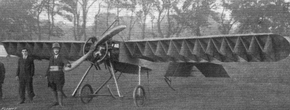
Three-quarter front view of the Cordner monoplane No.2. The improved version of 1911-1912.
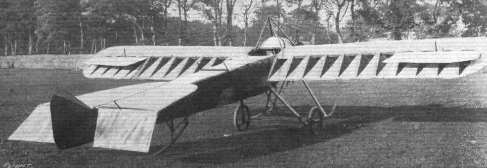
Three-quarter rear view of the Cordner monoplane.
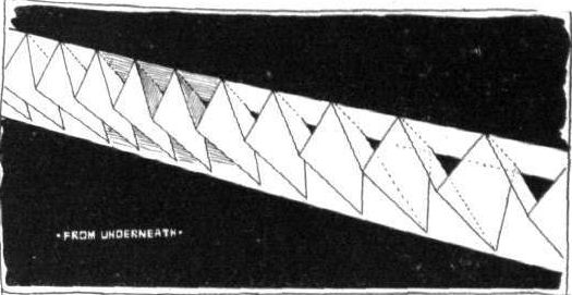
Sketch showing peculiar wing design of the Cordner monoplane.
Flight, February 5, 1915.
THE AIRCRAFT MANUFACTURING CO.'S NEW GUN-CARRYING BIPLANE.
PROBABLY no other type of aeroplane presents greater difficulties and more complex problems to be solved than does the propeller or "pusher" type, and when a new machine of this class is produced one may be perfectly certain that the reason for its appearance is not that the design of a pusher offers a short cut to success, but that there is a demand existing for a machine of this type for special purposes. The reasons which make the design of a propeller biplane a matter of great difficulty may not be immediately apparent, but they are very real, and some may be briefly referred to. In the first place, there is a question of side areas which must be carefully proportioned if spiral instability is to be avoided. A very deep nacelle, while possessing the advantage of protecting the occupants against the rush of air, and at the same time giving a better stream-line, necessitates larger vertical surface in the tail-fin and rudder. Large vertical surfaces for a given weight again necessitate very careful arrangement of these surfaces in relation to the centre of gravity, which latter must of course also be in its proper position relatively to the main planes. Again, the shape of the nacelle enters very considerably into the question, as a nacelle having curved sides would obviously not have the same effect in a relative side-wind as one with perfectly flat sides of the same projected side area.
By making the nacelle low the side area may be reduced, but then the difficulty enters of providing the necessary clearance between the ground and the propeller, if the latter is to be kept of the desired diameter. This difficulty can, of course, be overcome by lengthening the struts of the under-carriage, but practical considerations put a limit to the length it is advisable to make these members if extra head resistance and a "stilty" chassis are to be avoided. The arrangement of the engine in the rear of the nacelle is another problem which has to be dealt with. In order to make the nacelle of good stream-line form it should taper towards the rear, but where an air-cooled engine is used provision must at the same time be made for at least a portion of the cylinders to receive the necessary amount of draught to keep them from overheating, and this arrangement will partly spoil the stream-line form of the nacelle. Owing to the proximity of the tail planes to the propeller in an engine-behind machine, the effect of the slip stream on the former is a factor that cannot be neglected, and for which allowances must be made in the design and position of the tail planes.
In our photographs is seen the new biplane designed by Mr. G. de Havilland, and built by the Aircraft Manufacturing Co., Ltd., which is an attempt to produce an aeroplane capable of being used as a fighting machine carrying a gun, and at the same time being reasonably stable and sufficiently fast to meet the requirements of the military authorities. Whether Mr. de Havilland has completely achieved his object the trials will show, but there can be no doubt that as an experiment the new machine gives promise of great possibilities. During its preliminary trials Mr. de Havilland flew it repeatedly with his hands off the controls, and when he did a turn, the machine automatically banked to the right degree for the speed and the radius of the curve. Thus there seems little doubt that the stability of the new biplane is all that can be desired in a machine that does not lay claim to being absolutely inherently stable.
As regards speed, this has not been definitely determined yet, as the propeller fitted during the preliminary trials was not quite suitable, allowing the 70 h.p. Renault engine to run at much higher revolutions than those for which it is designed. Even under those unfavourable conditions the machine showed a speed of over 70 m.p.h. as registered on the speed indicator, so that there is every reason to believe that when a suitable propeller has been fitted this figure will be considerably exceeded. This is distinctly good, especially as the machine was originally designed for an engine of 80 h.p. When landing the speed appeared to us to be quite low for so substantial a machine, although the designer did not at any time attempt to land it at its absolute minimum speed.
In its general appearance the new gun-carrier is of very pleasing lines, and, as one expects from a firm of so high standing as the Aircraft Manufacturing Co., Ltd., the workmanship is excellent. In later machines of this type several of the constructional details will be altered, as the experience obtained with the present one suggests various improvements, but the general arrangement will be retained.
From the accompanying photographs it will be seen that the main planes have a very pronounced dihedral angle, which does not, however, extend throughout their whole length, but is confined to the outer ends of the planes from the second pair of inter-plane struts. The centre sections of the wings are straight. The end sections of the planes are attached to the centre sections by steel clips, and as upper and lower end sections are identical, one spare wing may be used to replace either a lower or an upper extension in case of damage by simply changing the fittings. The nacelle, which is of rectangular section with slightly curved sides formed by longitudinal stringers, projects forward from the main planes a considerable distance, and in the nose the top covering slopes down to allow of pointing the gun with which it is intended to fit the machine at a fairly steep downward angle. Pilot's and passenger's seats are arranged tandem fashion, the pilot sitting at the rear in order to allow the gunner a free range. In the rear of the nacelle is mounted a 70 h.p. Renault engine in such a manner that the tops of the cylinders project sufficiently far above the nacelle covering to ensure good cooling. The bottom of the rear portion of the nacelle is covered with an aluminium shield in order to preserve as far as possible the stream-line form, and as the two halves of the lower plane are attached to the sides of the nacelle and do not run right across it the air has here a comparatively unrestricted flow.
The tail planes are carried on an outrigger of four steel tubes, and the fixed horizontal tail plane is hinged to the two upper of these tubes, while at the rear it attached to the vertical rudder post by a pin joint such a manner that the angle of incidence may be easily altered to compensate for any alteration of the weight carried in the nose of the nacelle. To the trailing edge of the fixed tail plane is hinged a divided elevator, whilst horizontally the machine is directed by a partly balanced rudder pivoting round the vertical tubular rudder post. The fixed vertical surface of the tail consists of a small fin placed on top of the fixed plane. A pivoted tail skid mounted on a downward extension of the rudder post protects the tail planes against contact with the ground, and as there is a considerable weight on the tail when rolling the skid acts at the same time as a very effective brake. In order to further reduce the speed on landing an air brake is fitted behind the pilot's seat, consisting of two small planes mounted on a tube resting on the upper longitudinals of the nacelle. This air brake is operated from the pilot's seat by means of a small hand lever, and works by being turned broadside on, thus offering a certain amount of extra head resistance. Control is by means of a single lever and a foot bar. Both upper and lower planes are fitted with ailerons.
The undercarriage is of the simplest possible type, and appears to be very suitable. It consists of two pairs of struts forming two "V's," the apices of which are connected by two transverse members placed a short distance apart, and between which are accommodated the stub axles. Springing is provided by coil springs, and the rebound is taken by a piston working in a cylinder filled with oil. This type of under-carriage has proved very efficient, and has, among other advantages, that of preventing almost entirely the bouncing to which machines fitted with the ordinary rubber shock absorbers, are liable. By undoing two bolts one of the wheels and its shock absorbing arrangement may be removed for inspection or repair. A stream-line casing encloses the the whole shock absorber, and the under-carriage therefore offers a minimum of head resistance. As the wheel track is comparatively narrow, small skids are fitted near the tips of the lower plane in order to protect this in case the machine rolls slightly over to one side.
Although the new machine has not, up to the time of writing, had an opportunity of being exhaustively tested, the preliminary trials were very encouraging, and Mr. de Havilland is to be congratulated upon his attempt to solve a difficult problem, and the Aircraft Company for the way in which they have carried out the construction.

The D.H. 1. - A pusher two-seater with 70 h.p. Renault engine. Capt. de Havilland is in the pilot's seat.
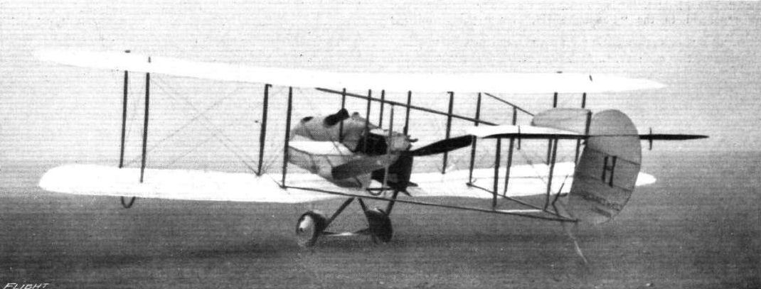
Three-quarter rear view of the new Aircraft Co. biplane.
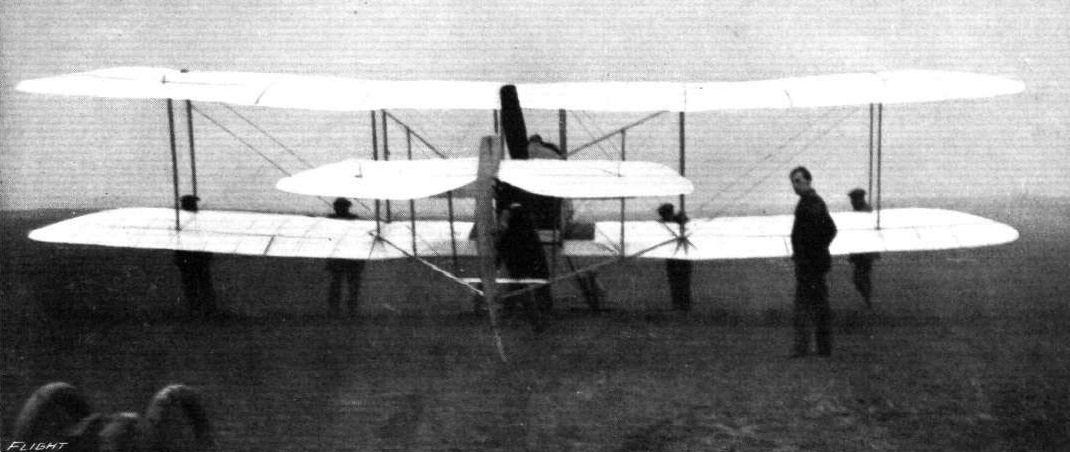
Rear view of the Aircraft Co.'s new biplane.

A three-quarter front view of the de Havilland machine in the air.
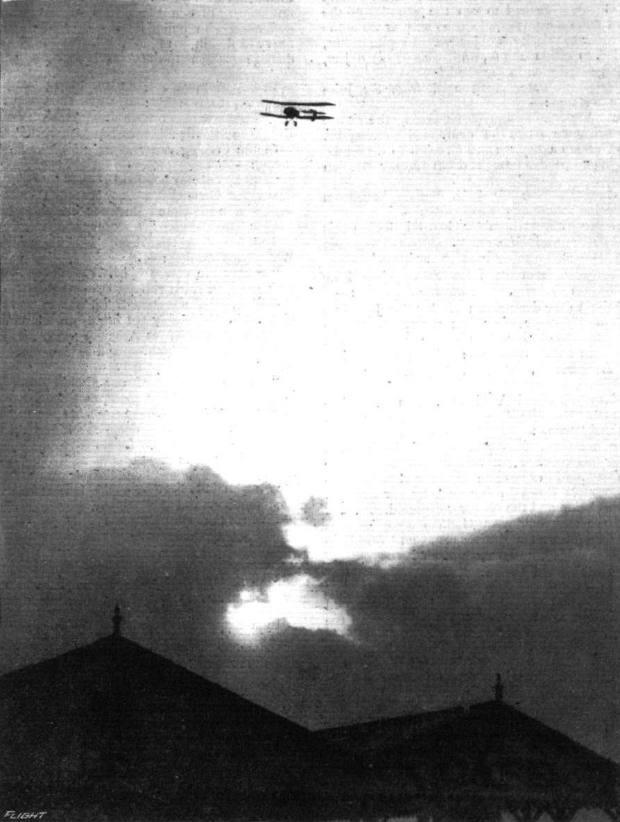
ANOTHER EVENING SCENE AT HENDON. - Mr. De Havilland on his De Havilland biplane.
Flight, October 22, 1915.
CONSTRUCTIONAL DETAILS.-VII.
<...>
The two examples given of the single axle and single-pairs-of wheels form of undercarriage are similar in type and differ in detail construction only. In the Dyott monoplane the axle runs right across from skid to skid, while in the Sopwith Scout the stub axles are pivoted in the centre, half way between the skids, and move up and down between two transverse members. Bracing of the front portion of the undercarriage is effected in the Dyott machine by a transverse compression member and diagonal cross-bracing, while in the Sopwith there is no such transverse member in front, its place being taken by cables running outwards from the skids to the main planes.
<...>
Various types of double skid undercarriages.
Flight, November 12, 1915.
CONSTRUCTIONAL DETAILS.-X.
<...>
Another form of simple Vee undercarriage is that of the Eastbourne Aviation Co.'s monoplane. In this machine the wheel track was comparatively wide, necessitating a differently-shaped apex of the "Vee." The two struts, it will be seen, converge a short distance above the wheel axle, and are here joined to a vertical block of wood, in which is cut a slot for the axle. The axle runs right across from side to side, buckling in the centre being prevented by a Vee formed by two wires as shown, while the rebound is taken by a rubber cushion secured to the tubular transverse member of the undercarriage. The cabane of steel tubes in the centre of the chassis does not, of course, form part of it, but serves as a support for the lift cables, the machine being a monoplane.
<...>
Various "Vee"-type undercarriages constructed of wood.
Flight, November 5, 1915.
CONSTRUCTIONAL DETAILS.-IX.
<...>
The undercarriage of the E.A.C. biplane has been included under the heading of simple "Vee" undercarriages, since the small tusks with which it is fitted cannot be said to be skids properly speaking. They are in fact formed by a forward extension of the rear chassis struts, and are here stiffened by webs in the manner shown in the sketch.
<...>
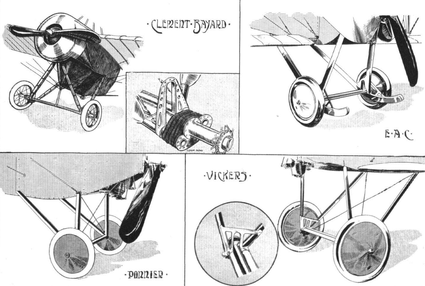
Various undercarriages of the "Vee" type.
Flight, October 29, 1915.
CONSTRUCTIONAL DETAILS.-VIII.
<...>
Somewhat unusual in arrangement was the undercarriage of the old Flanders biplane shown in one of our sketches. This chassis, it will be seen, is extremely simple, and offers a minimum of head resistance. The body is very deep in front and of pentagonal section, so that the hickory skid can be fastened directly to the lower fuselage member. Anchored to the keel are the two stub axles that carry the wheels. The method of springing is shown in the detail sketch, which is, we think, self-explanatory.
<...>
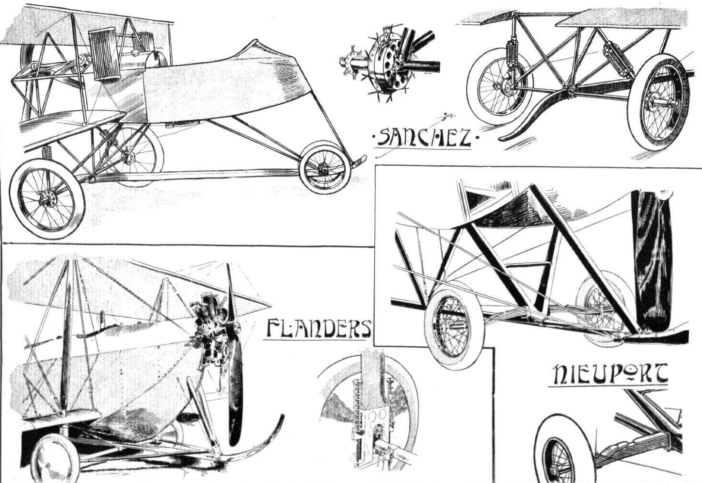
Various types of single-skid undercarriages.
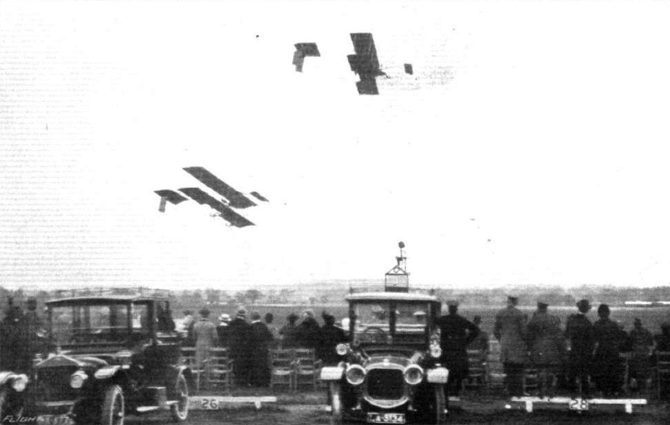
HENDON 1915 SEASON OPENS. - Mr. Barrs leading in the Six Laps Race, which he won.
Flight, April 9, 1915.
EDDIES.
Once inside the gates my first objective was the wind gauge in the paddock. Even from a distance of several yards the little pen which influences to such a large extent the amount and character of the flying, could be seen to be moving up and down in a series of violent jerks, remindful of the band conductor's baton. My visions of "stunt" flying faded in an instant, and instead I began to picture an afternoon without a single flight. From casual remarks dropped by some of the visitors, I received the impression that the majority of these were fully aware of the dangers of airwork under the prevailing weather conditions, a fact which speaks well for the educational value of the meetings held at Hendon before the war. It was, therefore, more with a feeling of pleasant surprise than with one of disappointment at seeing no flights earlier in the afternoon, that the public greeted the appearance towards evening of Mr. Graham on "Lizzie." His performance was truly a magnificent one, but personally I felt greatly relieved when he had landed safely, after giving a demonstration of his steep spirals, for the wind was tricky and treacherous. And, after all said and done, "Lizzie" has an engine of 50 h.p. only. However, all went well, and every credit is due to "Lizzie's" owner for his plucky stunt, and for the masterly way in which he handled his machine.
HENDON 1915 SEASON OPENS. - Mr. Graham flying "Lizzie" in half a gale of wind on Good Friday. Mr. Graham was the only one to make a high flight.
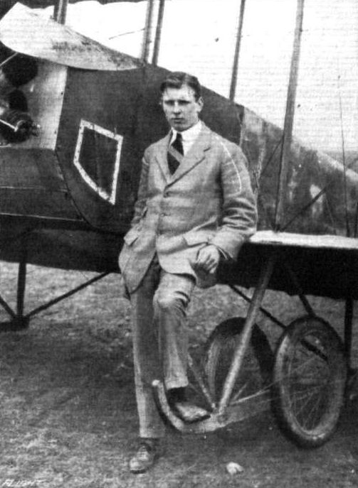
The man who bought and files "Lizzie," Mr. C. A. Graham.
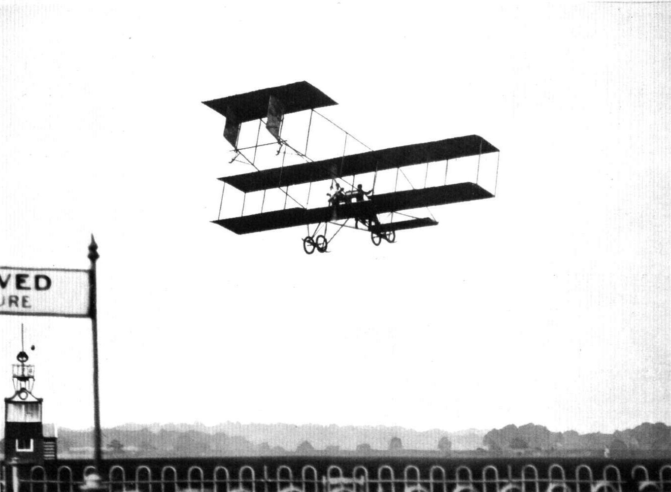
The end of a fine vol plane by Mr. J. S. B. Winter, with a passenger, at Hendon, on the Grahame-White school 'bus.
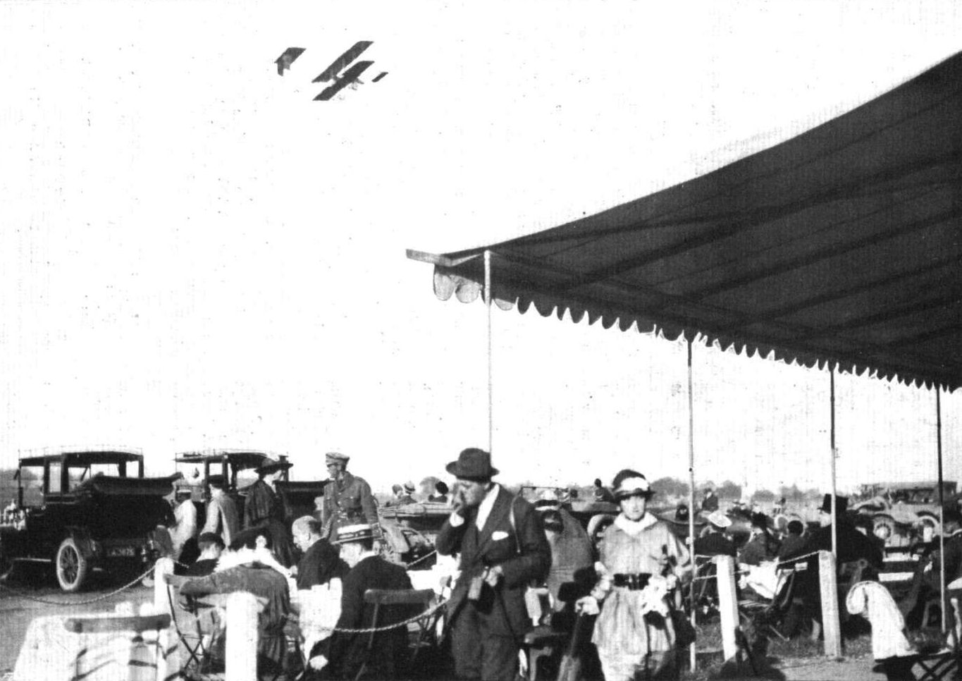
A brilliant day brought a goodly gathering of visitors to Hendon on a recent Sunday, and tables for al fresco teas were in great demand. Our photo, shows the scene during the afternoon.
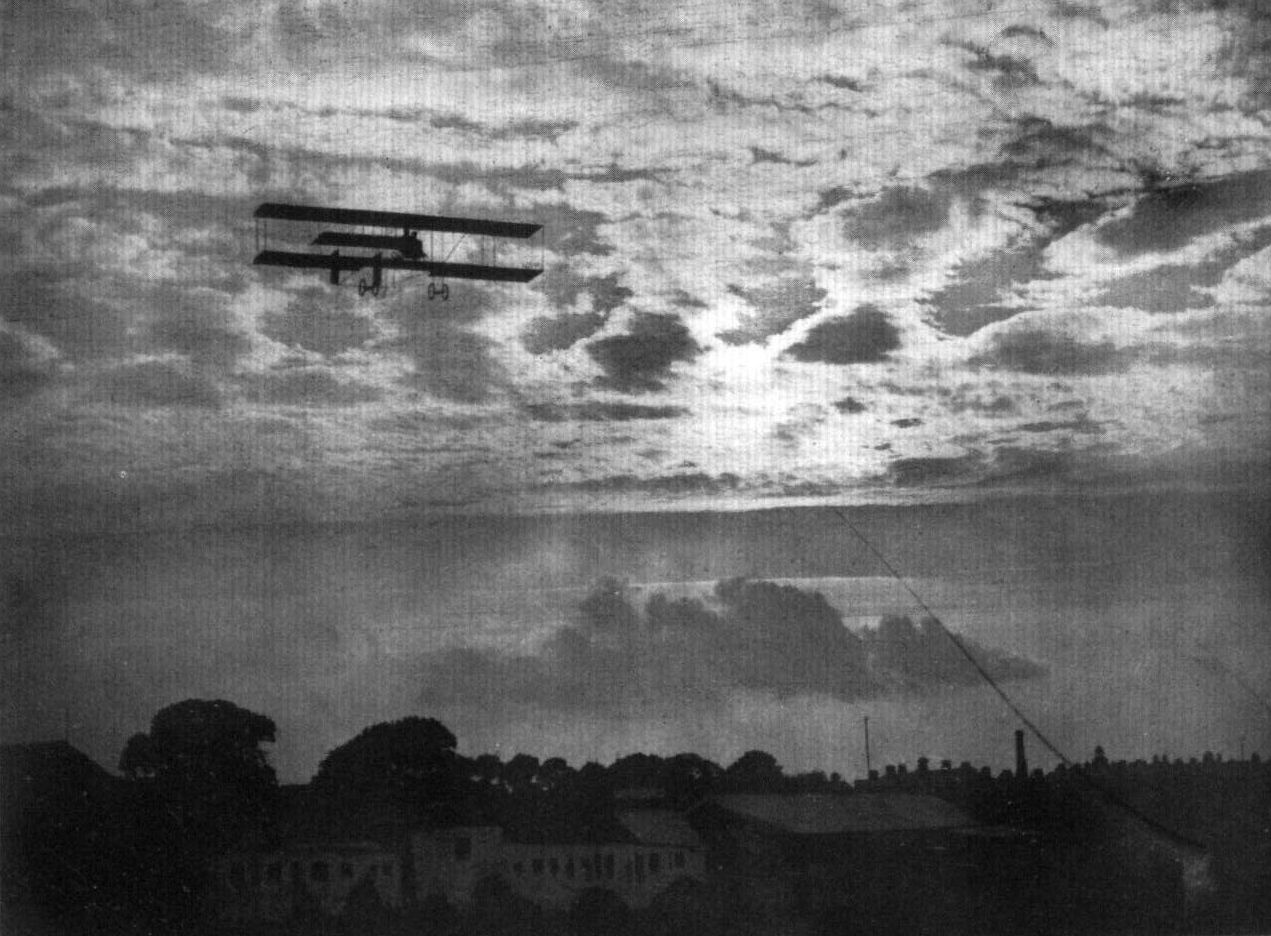
AT EVENTIDE WHEN THE BIRDS COME TO ROOST. - A cloud study at Hendon.
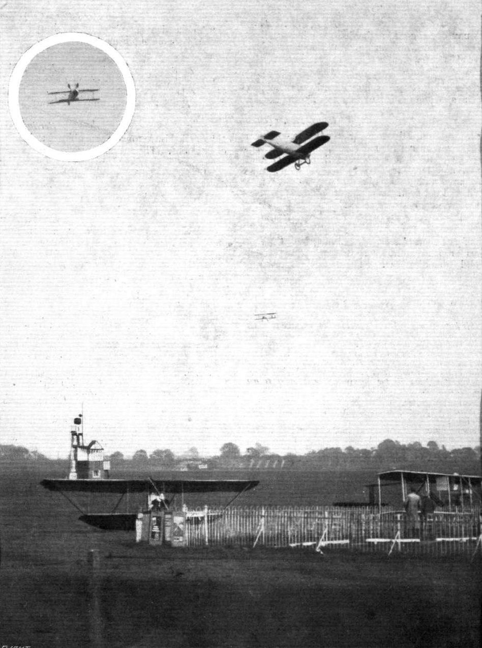
AT HENDON - A STRANGER MAKES A "COURTESY" CALL. - The machines in the air are: top, Vickers scout flown by Mr. Harold Barnwell; and below, a Grahame-White biplane. Inset at the top, left, is the Vickers scout witl its chassis heavenwards, during one of the loops which it made upon its "courtesy" call at Hendon, and to which reference was made in "Eddies" and Hendon Notes last week.

After Work, Recreation. - Mr. Marcus D. Manton about to take a wounded soldier for a trip in the air at Hendon. Note the comrade who is wishing him a melo-dramatic farewell.
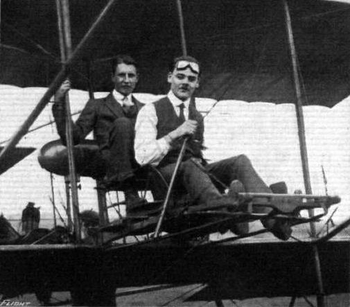
KEEPING COOL. - Mr. M. D. Manton was making passenger flights at Hendon in his shirt sleeves during the heat last Saturday.
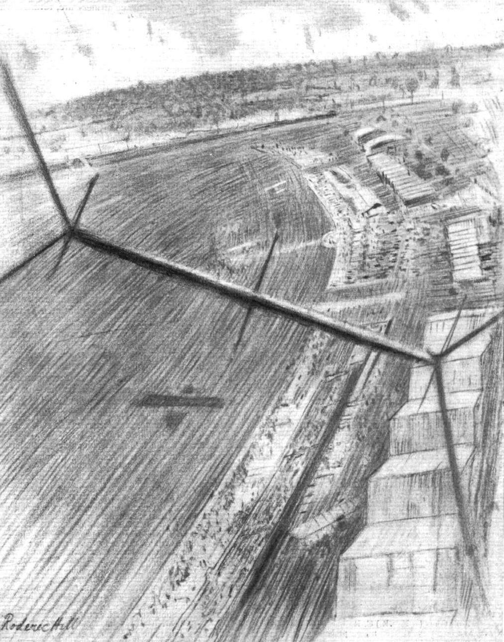
THE COUNTRY, AS SEEN FROM AN AEROPLANE. - View of Hendon Aerodrome from a 50 h.p. Grabame-White biplane, piloted by Mr. Winter, at an altitude of 400 ft. From a sketch actually made during the flight by the artist, Mr. Roderic Hill. In the distance is the Midland Railway and Hendon Hill, surmounted by the church. The elevator of the machine is seen in front right across the picture.
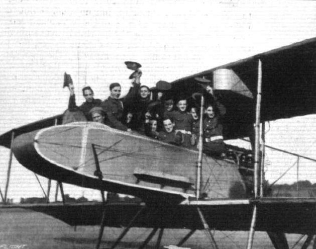
A contingent of the Queen's Surreys, at Hendon, testing the holding capacity of the Grahame-White "char-a-bancs." M. Osipenko, the Russian pilot, is in the pilot's seat.
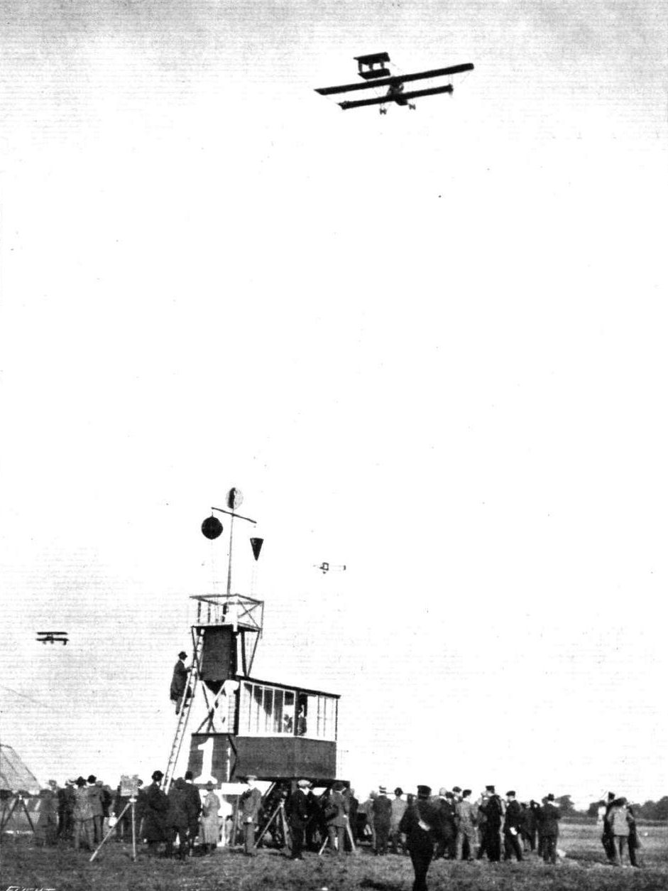
A REMEMBRANCE OF HENDON BEFORE THE WAR. - A trio in the air. Note on the five-seater the men being carried on the wing tips.

Mr. Osipenko on the Graliame-White 5-seater passenger-carrying 'bus at Hendon.
Flight, November 5, 1915.
CONSTRUCTIONAL DETAILS.-IX.
<...>
The third undercarriage on this page is that of the Grahame White "pusher" biplane. It is of a similar type as the other two, but has, it will be seen, three struts on each side instead of two.
<...>
CONSTRUCTIONAL DETAILS.-IX.
<...>
The third undercarriage on this page is that of the Grahame White "pusher" biplane. It is of a similar type as the other two, but has, it will be seen, three struts on each side instead of two.
<...>
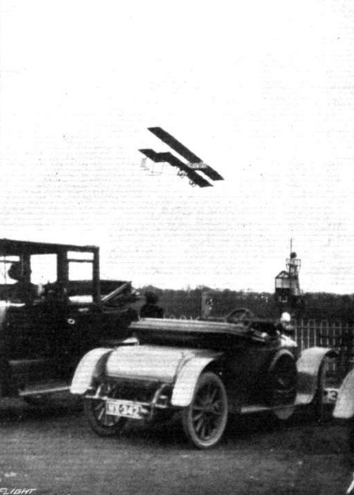
HENDON 1915 SEASON OPENS. - The new Grahame-White "pusher" in flight.
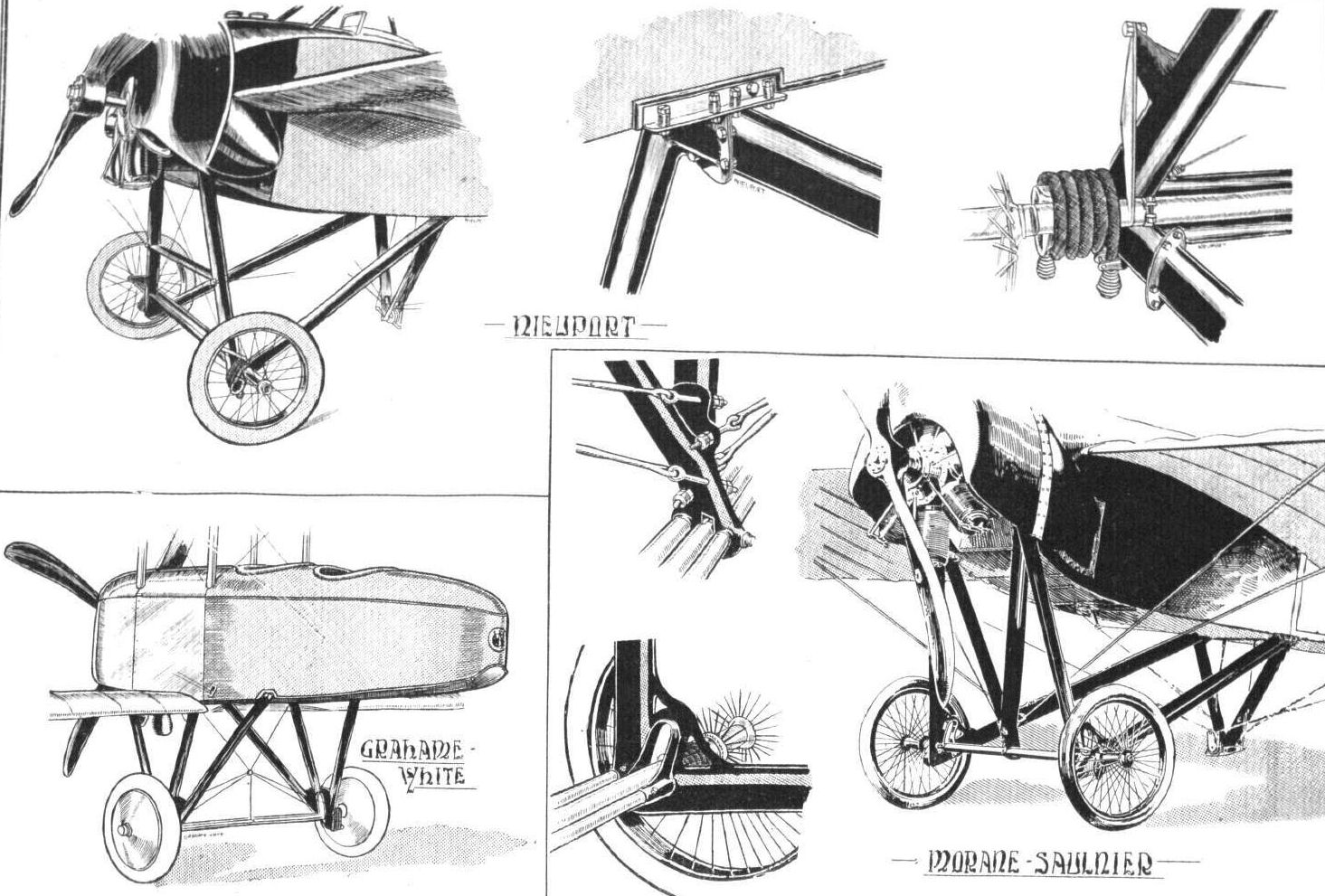
Various undercarriages of the "Vee" type.
Flight, April 16, 1915.
EDDIES.
IT was a pity that the high wind prevailing on the first days of the Easter meeting at Hendon and a refractory engine on the Monday prevented the visitors from seeing the Grahame-White tractor showing her paces. Manton decided, very wisely, that in view of his short experience on so fast a machine it would have been unwise to try her out in such a vicious wind. He got her going for a couple of nights, and then the engine decided, it being a Bank Holiday, to take a rest. So it came about that Manton had to abandon his intention of giving a demonstration of speed flying for the benefit of the crowd of visitors which had gathered in the afternoon. It is, however, only an attraction postponed, and I shall look forward to her proper debut at the next meeting of the season.
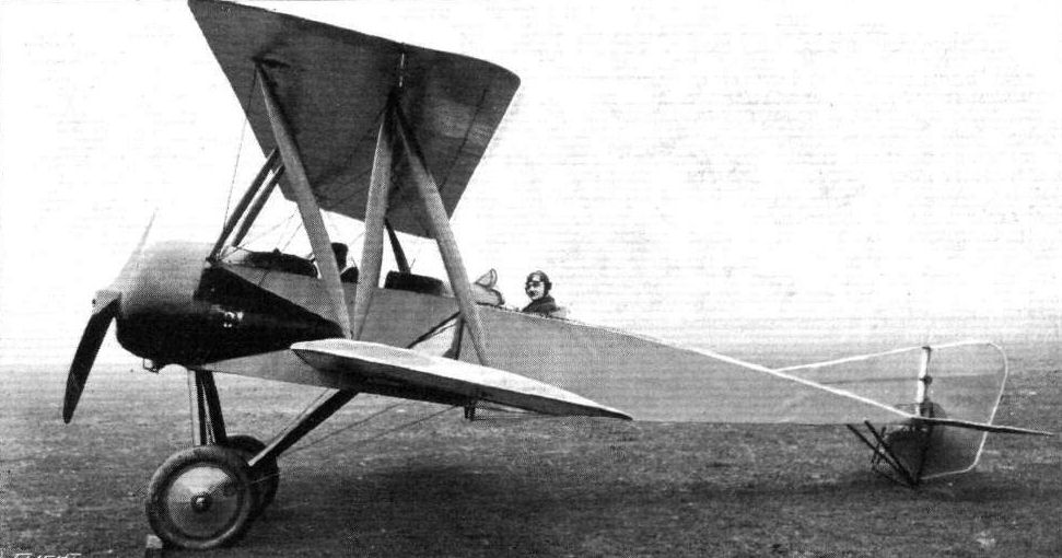
The Grahame-White tractor biplane which was originally designed for the seaplane circuit of Britain, and which has now been fitted with a chassis for use over land. It was flown by Mr. Manton - who is seen in the pilot's seat - a short time ago, and proved very fast. One or two minor alterations were, however, found to be desirable, and when these have been effected the machine will be out again.
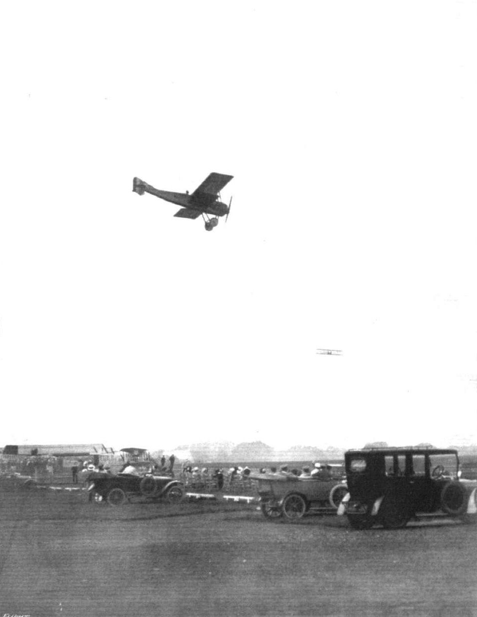
CIRCLING AT HENDON. - Mr. Marcos D. Manton in the G.-W. Scout. In the distance one of the Beatty-Wright.

Flight, June 18, 1915.
EDDIES.
AFTER numerous delays caused by the various repair jobs that are inevitable at a flying school, the Hall fuselage biplane has at last been completed and put through her paces. During the very first flight the new biplane was found to handle remarkably well, being very fast, about 62 m.p.h., I understand, and climbing splendidly. Since then Mr. Hall has been for a number of jaunts to make sure that the machine is in absolutely perfect trim before turning her over to the more or less tender mercy of the pupils. On one occasion last week he put her climbing capabilities to the test, and came down from a good altitude in a series of beautiful spirals, mainly to see if there should, by any chance, be a tendency to spin. This was conspicuous by its absence, and about the only objection that could possibly be raised is that the machine is somewhat sensitive on the elevators. This is hardly to be wondered at when it is remembered that instead of the large flexible tail plane fitted previously, there is now only a small fixed stabilising plane and two large elevator flaps. In the hands of so experienced a pilot as Mr. Hall this sensitiveness is, of course, no drawback, rather the reverse, and should pupils prefer a little less of it, it would be quite a simple matter to fit a slightly larger tail plane. The Hall equipment now includes machines ranging in power from 35 to 50 h.p., and pupils will be able to proceed by progressive stages from the smaller, lower powered biplanes to the higher powered and fast ones. A good idea of the new mount may be gained from the accompanying photographs.
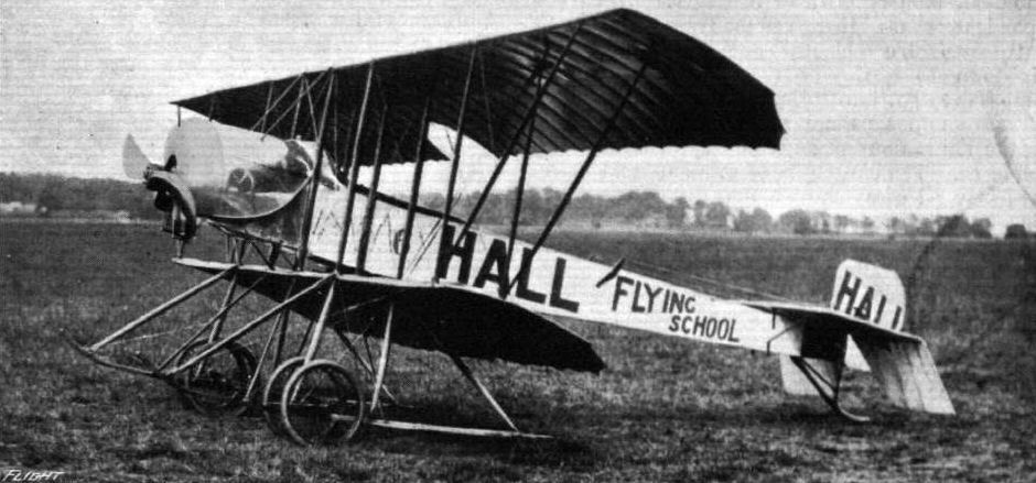
THE LATEST TRACTOR BIPLANE AT THE HALL FLYING SCHOOL, HENDON. - Three-quarter view from the front.
The Hall biplane of 1914-1915 used Caudron wings.
The Hall biplane of 1914-1915 used Caudron wings.
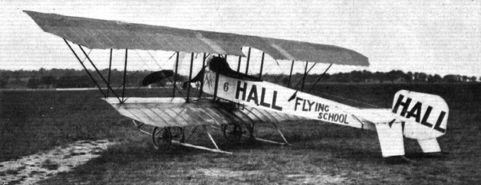
THE LATEST TRACTOR BIPLANE AT THE HALL FLYING SCHOOL, HENDON. - Three-quarter view from the back.
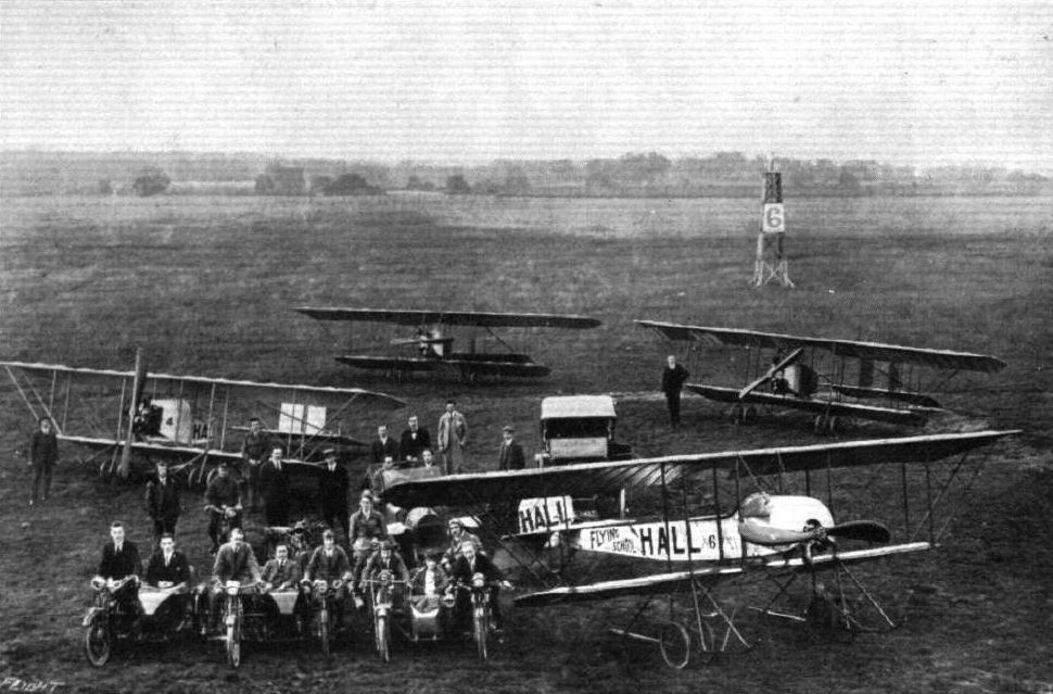
A recent photograph of a number of pupils and machines of the Hall Flying School, Hendon. Mr. Hall is standing in front of machine No. 4, on right of propeller.
Flight, October 29, 1915.
CONSTRUCTIONAL DETAILS.-VIII.
<...>
The second alternative referred to above is to obtain the required springing of the alighting wheels, not by making the axle itself flexible, but by running extra chassis members from a point on the axle just inside the wheel up to some portion of the body of the machine, and to incorporate with these members some form of shock absorbing device. This device may either be in the form of coil springs or rubber shock absorbers. An illustration of the former method is shown in the sketch of the undercarriage of the Handley-Page monoplane. Here the coil springs are enclosed in telescopic steel tubes, and the short piece of rubber shown in one of the detail sketches serves the double purpose of taking up the shock of the rebound and of preventing the inner tube from slipping out of the outer when the machine leaves the ground.
<...>
Various types of single-skid undercarriages.
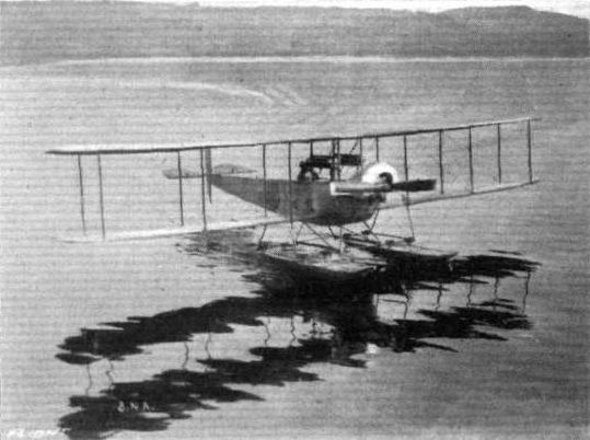
The waterplane of the Northern Aircraft Co. at their school on Lake Windermere. N.A.C. Avro.
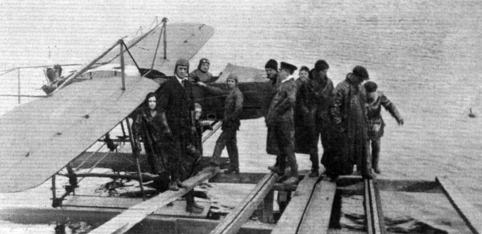
SOME OF THE PUPILS AT THE NORTHERN AIRCRAFT FLYING SCHOOL ON LAKE WINDERMERE. - ln the pilot's seat Mr. W. Rowland Ding, and from left to right, Prob. Flight Sub-Lieuts. Hume, Graham, Layer, Mr. Yates, Prob. Flight Sub-Lieuts. Permt, Hodges, Messrs. Part and Railton, Prob. Flight Sub-Lieut. Clifford, and Mr. Robinson.
AT THE N.A.C. SCHOOL ON LAKE WINDERMERE. - Two of the machines in use for pupils. Left: The N.A.C. 80 h.p. Gnome biplane just "off"; and, in the foreground, the 100 h.p. Anzani-Blackburn monoplane.
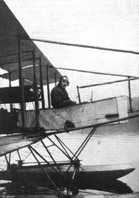
Mr. D. S. C. Macaskie, who has recently obtained his certificate at the Northern Aircraft Company's school, Bowness, Lake Windermere.
Flight, July 2, 1915.
THE NEW L. AND P. BREVET BIPLANE.
WHEN the London and Provincial Aviation Co. made their debut as aeroplane constructors with a little tractor biplane, 35 h.p. Anzani engine, it was at once apparent that no trouble or expense had been spared in rendering the construction as strong and reliable as first-class material and good workmanship could make it. Subsequent machines have all had the same characteristics, with the result that the firm is now enjoying, and justly so, a reputation for excellence of workmanship and finish. The first 35 h.p. school biplane was soon followed by several others of a similar type, and for each a large stock of spare parts was completed so as to facilitate replacements in case of the breakages that are inevitable where machines are handled daily by a number of inexperienced pupils. There can be little doubt that by working on these lines the output of the school has been greatly increased, such accidents as have occurred having entailed only short delays.
Although the little 35 h.p. biplanes flew exceptionally well it was soon found that slightly higher powered machines would be a decided advantage for the more advanced pupils, and it was not long before a 45 h.p. machine of similar type, but differing as regards dimensions, made its appearance. So well did this two-seater pass its preliminary trials that it was promptly purchased by Mr. W. G. Moore, and is now greatly used for passenger-carrying and solo flights.
No sooner had this machine left the stocks than a new biplane was put in hand, this time a single seater fitted with a 35-40 h.p. Anzani engine. Intended for use as a brevet machine, it was finished and tested just recently, and found to be well up to the usual L. and P. standard as regards ease of handling and climbing power. In affording the pupils an opportunity of getting acquainted with the control of a faster and higher powered machine, the new brevet biplane, which is illustrated in the accompanying sketches, scale drawings, and photographs, forms a stepping stone to the service machines that those of the pupils who upon completion of their tuition join the R.F.C. or the R.N.A.S. will have to fly. In order that they may familiarise themselves with the use of all the necessary instruments, the dash of the L. and P. brevet machine has been uncommonly well equipped with these accessories, uncommonly, that is to say, for a school machine.
Like all previous L. and P. biplanes, the latest brevet machine has a very strong family resemblance to the Caudrons, being characterised by the same type of flexible wings and tail plane, and having a similar short nacelle. The main planes have the two spars placed comparatively close together and a very wide flexible trailing edge. In order to provide a better entering edge the front portion of the top of the planes is covered for a distance of some 9 ins. rearward from the front spar with a strip of three-ply wood resting on top of the ribs and preventing the fabric from sagging. Only the part of the wings between the spars is double surfaced, the fabric being stitched down a few inches behind the rear spar, whilst the trailing portion of the ribs is enclosed in pockets formed by fabric. The reason for this form of construction is, of course, that when the flexible ribs bend upward when the machine is in flight no folds are formed as would have been the case had the whole of the wing been double surfaced. The same principle is employed in the tail plane, which, as our readers are no doubt aware, serves a double purpose in not only acting as an elevator by being flexed up and down, but also warps laterally in conjunction with the main planes, the control cables passing over king posts in order to ensure this action.
The undercarriage is formed by two pairs of wheels slung by means of rubber bands from the long skids, which are projected backwards to form the lower tail booms. The upper tail booms run from the rear spar of the upper plane to the vertical king posts carrying the control cable leads. Two partly balanced rudders are mounted on top of the tail plane, and are stayed by steel tubes fitted with wooden fairings.
The short nacelle which encloses the pilot and tanks is sufficiently wide and deep to afford plenty of elbow room, and the top covering which slopes up from the front to the instrument board deflects the air so that the pilot receives a minimum of draught. The pilot's seat, which is of the bucket type, is placed in the extreme rear of the nacelle, and in front of it is the central control lever which operates warp and elevator. A pivoted foot bar is mounted on the floor of the nacelle, and from this cables run back to the rudder. So placed that all the instruments can be readily seen from the pilot's seat is a dash board carrying, as we have already said, a very complete set of instruments including air speed indicator, tell-tale oil glass, clock, compass, altimeter, and revolution indicator. In front of the dash board and under the sloping bonnet are mounted the petrol and oil tanks, from where the fuel and lubricant run to the engine. The latter - a 35-40 h.p. Anzani - is mounted on a steel plate capping the front ends of the four longerons of the nacelle. Aluminium inspection doors on the side give access to the interior for inspection of oil pump and magneto.
Two exhaust pipes, to each of which are welded three short branch pipes attached by bolts to the exhaust ports in the top of the cylinders, carry the exhaust gases away underneath the nacelle, thus doing away with the continuous spray of smoke and oil with which the 35 h.p. engines are in the habit of regaling the pilot. Apart from adding in this manner to the comfort of the occupants, the exhaust pipes serve to a certain extent as silencers.

Brigadier M. #. Franchomme, who has just taken his brevet at the London and Provincial School, Hendon. Brigadier Franchomme is a member of the Belgian King's Guides regiment, and is attached to the Royal Belgian Flying Corps. He was in charge of the Belgian armoured cars in Antwerp.
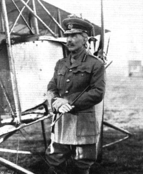
General Lewis Hall, C.B., who has just taken his Royal Aero Club ticket at the London and Provincial School, Hendon, on an L. and P. biplane. General Hall, whose age is 62, most certainly is an instance contradicting the generally accepted theory that flying is a young man's game.
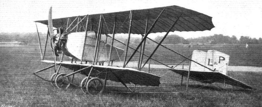
Three-quarter front view of the L. and P. biplane.
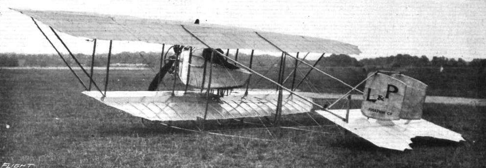
Three-quarter rear view of the L. and P. biplane.
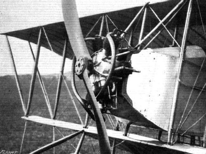
The 35-40 h.p. Anzant engine on the L. and P. biplane.

AT EVENTIDE. - An advanced pupil of the London and Provincial School flying at sunset at Hendon.
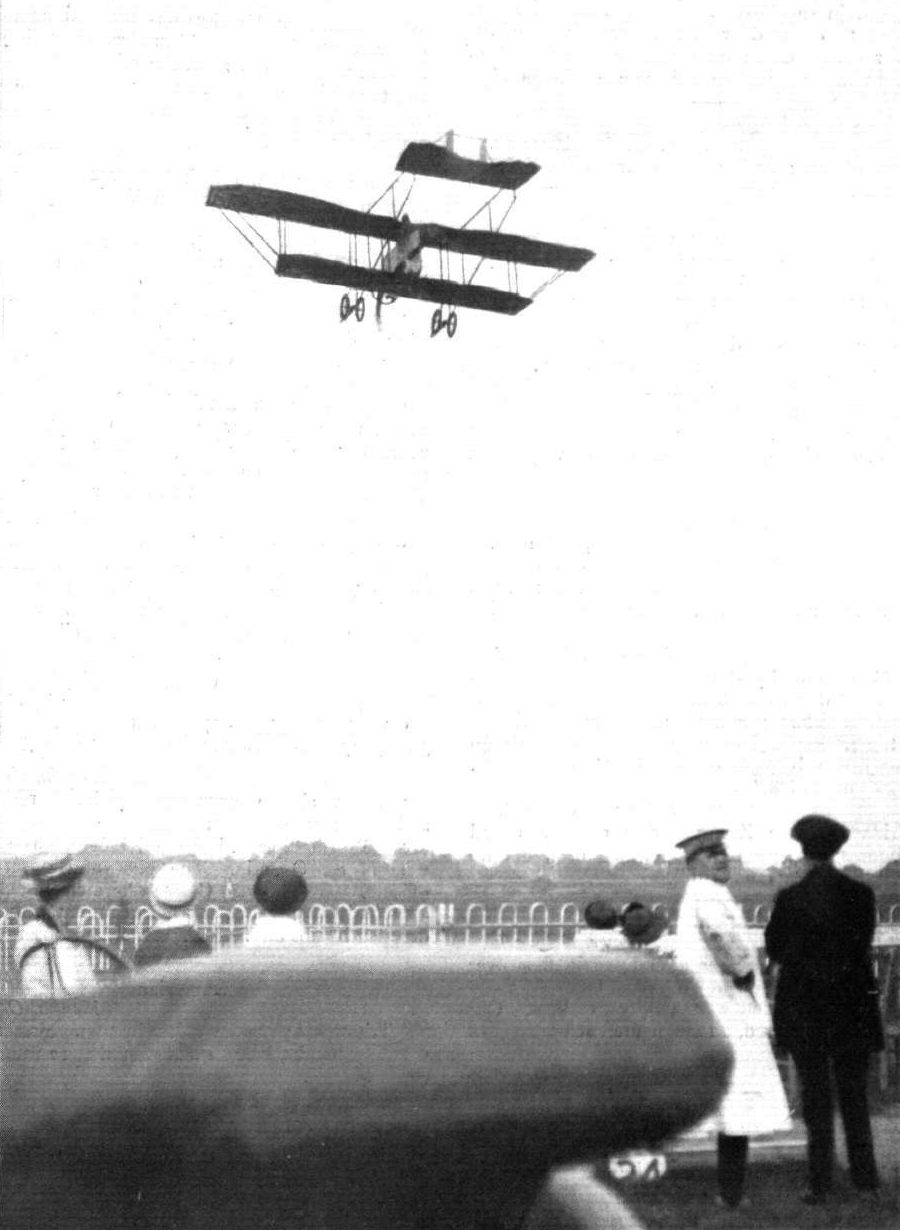
The finish of a fine spiral vol plane by Mr. J. H. Moore at Hendon.
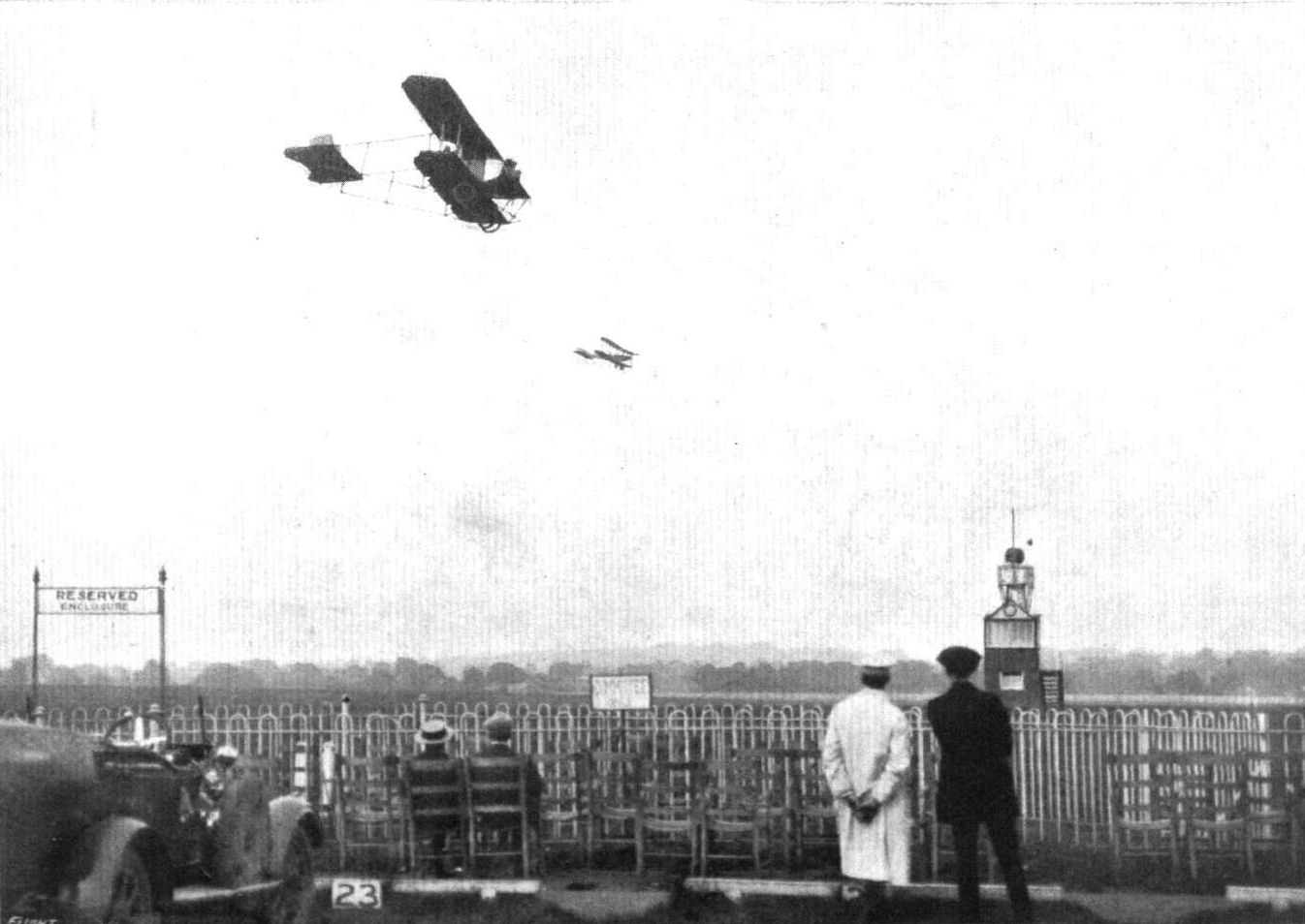
NECK AND NECK PAST THE ENCLOSURES AT HENDON. - Mr. J. H. Moore on his biplane, and Blackburn BE.2c.

Mr. J. H. Moore flying at Hendon Aerodrome on his biplane. On the ground a Blackburn B.E.2C just landed.

Sketch showing nacelle of the L. and P. biplane.

A spar hinge on the L. and P. biplane.
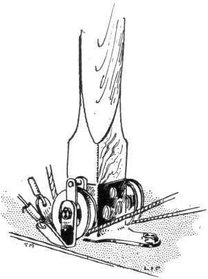
Sttut socket and warp cable pulleys on the L. and P. biplane.
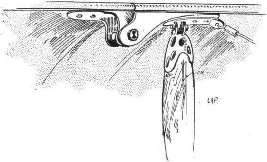
The hinged joint of the top plane extensions on the L. and P. biplane.
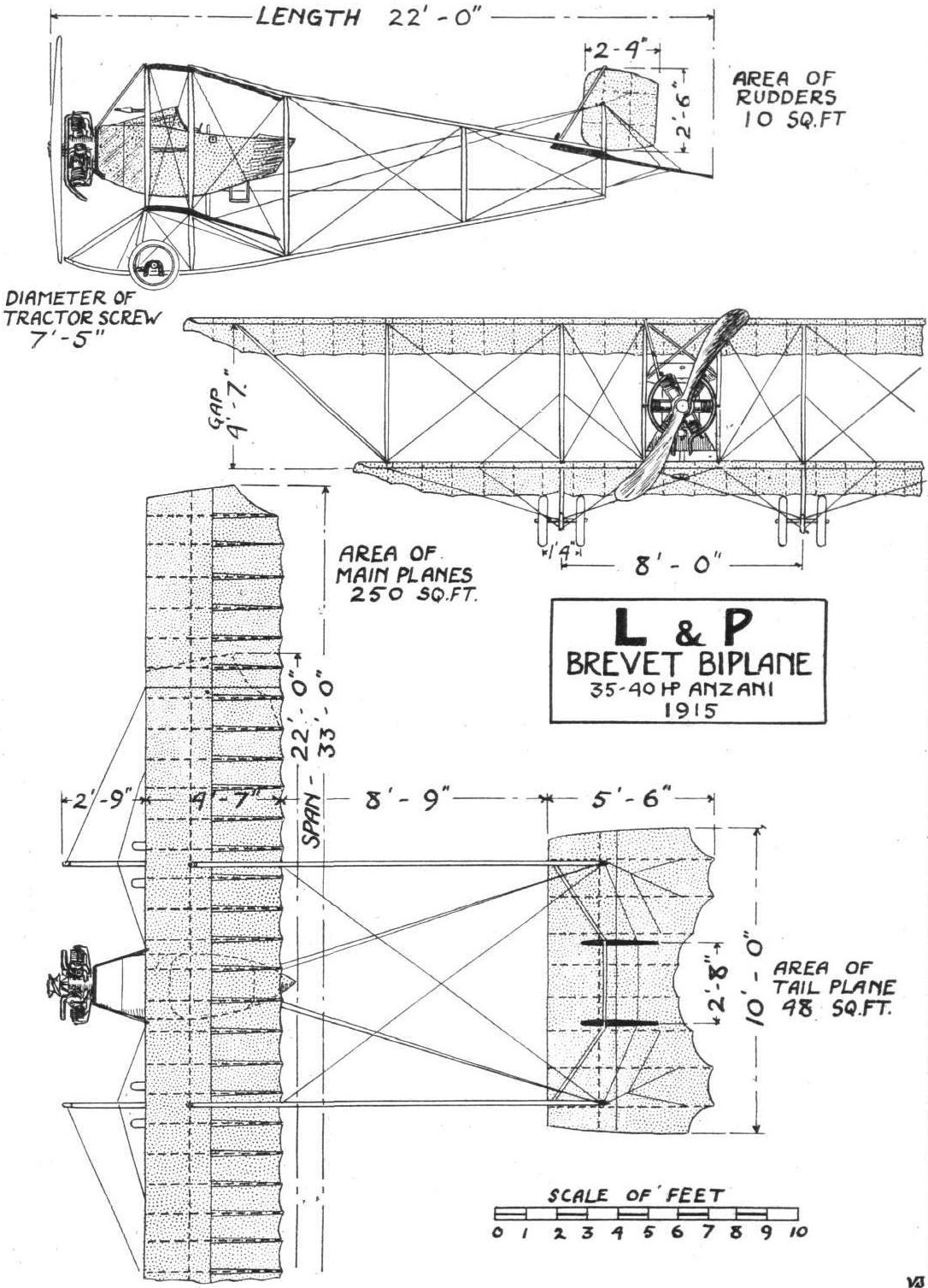
THE L. AND P. BREVET BIPLANE. - Plan, side and front elevation to scale.
Flight, February 5, 1915.
EDDIES.
Another new machine arrived at the aerodrome on Saturday. The newcomer has been designed and built by Messsr. Mann and Grimmer, the well-known model constructors, and is of unusual appearance. From an inspection of the various parts, as they lay in the L. and P. sheds, it is evident that, when erected, she will be a fuselage biplane with two "pushers." The body is very deep and covered with aluminium in front, whilst the rear portion is covered with fabric. The two seats are arranged in tandem, the pilot sitting far back and the observer being placed immediately behind the engine plate in the nose of the body. I learn that a 100 h.p. Anzani engine will be fitted, and as the new machine is of such original form, her performances will be watched with interest.
Flight, March 26, 1915.
THE NEW "MANN" BIPLANE.
AMONG the new machines that have made their appearance lately, one of the most original is the Mann "pusher" biplane, built by Messrs, Mann and Grimmer, and erected at Hendon a short while ago. As reported in FLIGHT some time back, it flew successfully for the first time of asking, and last week further flights were made, a few modifications having been made. On both occasions Mr. Rowland Ding was the pilot.
Briefly speaking, the Mann biplane is a fuselage machine with the engine in front and the two chain-driven propellers at the rear of the main planes. In the extreme nose of the very deep body is placed the seat for the observer or gunner, and from here an unrestricted view is obtained owing to the absence of a tractor screw to obscure the view. A 100 h.p. Anzani drives the two propellers through a shaft and chain transmission - designed by Mr. Leper, who has had many years experience with chain transmission - the shaft terminating at the rear in a spur gearing driving the sprockets, so that crossing of one chain is avoided although the propellers run in opposite directions.
A short distance behind the main planes is the pilot's cockpit, from whence the pilot is able to look straight down behind the lower main plain and to obtain a good view in a forward direction over the leading edge of the lower plane. The tail planes are of large size, and consist of the usual members, a fixed stabilising plane, a divided elevator, and the rudder. The under-carriage is of the wheel and skid type, the two disc wheels being carried on short stub axles sprung from the skids by rubber shock-absorbers.
The main planes, of which both upper and lower are fitted with inter-connected ailerons, have a slight backward sweep similar to that found in a number of German machines. This, however, only applies to the leading edge, as the trailing edge is straight, as seen in plan.
Owing to the unusual design of this machine, a considerable amount of interest attaches to its forthcoming trial flights. If the new "Mann" biplane proves a success from the aerodynamical point of view, it should be of value for military purposes, owing to the facility with which a gun can be mounted in the nose of the body.
EDDIES.
After a short rest in dock, during which a few alterations have been made, the Mann and Grimmer biplane was out again for a flight at Hendon on the morning of Friday last. Those who saw the flights agreed that an enormous improvement was noticeable, and that the machine must have been doing close on up to the 70 miles mark, the Anzani engine pulling like a demon. It appears that the propellers with which the "Mann" was originally fitted were too big for the engine, and that the improvements were chiefly due to the fitting of different propellers. The pilot was, as in its first flight sometime ago, Mr. Rowland Ding, who was highly pleased with the behaviour of the "Mann."
***
By the way, this week a few more details of the Mann and Grimmer creation appear on another page in FLIGHT, the Censor having now "released" these for publication. It will be remembered I hinted a few weeks ago, at official embargo having been temporarily enforced upon the issue of any particulars. The ways of officialdom are truly obscure.
Flight, April 9, 1915.
EDDIES.
Mr. Ding, of the Northern Aircraft Co., indulged in a couple of flights on the "Mann" biplane on Sunday, March 28th. He had hoped to try the machine in the strong wind that was asserting itself during the early part of the afternoon, but greatly to his disappointment it eased off directly the 'bus was brought out, thus preventing the wind test from being carried out. Instead, Mr. Ding made a couple of flights, each of about 15 minutes' duration, the first one solo, and in the second accompanied by the designer, Mr. Mann. On both occasions she got up to about 1,000 ft. and was flown "hands off." The designer has now come to the conclusion that a little extra power is required to make the machine fly as he wants her to, and a 125 h.p. Anzani is being fitted instead of the original 100 h.p. This should give the desired climb and speed, especially as the machine itself will be considerably lightened.
Flight, July 9, 1915.
FLYING AT HENDON.
THIS last week-end at Hendon saw some very good flying that was, however, not without an exciting incident or two. Of special interest was the re-appearance of the Mann twin-pusher biplane, now fitted with a 125 h.p. Anzani engine. The first flight in its altered condition was made on Tuesday of last week, when W. Rowland Ding took it up for a short trial. It was soon found that the propellers were unsuitable, several minor adjustments also being required, as it did not prove so fast as with the 100 h.p. engine. The necessary adjustments were completed by Saturday afternoon, and in the evening Ding took it up once more just as rain commenced to fall. Improvement was at once discernible by the way it got off and climbed, and after several circuits an altitude of 1,500 ft. was reached. At this height Ding executed some banked turns, and descending a few hundred feet indulged in some switchbacks to show the machine was under perfect control. This time the speed had been increased to 70 m.p.h. As the rain was getting somewhat unpleasant, Ding decided to descend, and proceeded to come down, in over the hangars. Needless to say, both Mr. Mann and Mr. Grimmer were "all smiles," but at the last moment these smiles faded, for just as Ding was entering the aerodrome a fledgeling, on one of the numerous machines of a type that has become very popular, was taxying right across in front of the descending machine. It was one of those moments when it was hard to tell whether or not the machine in front would pass by before the other landed. However, it was soon evident that a collision was there in the making, unless Ding could hop over the machine on the ground, for it was then too late to turn. Would the engine, which was well throttled down, pick up quickly enough? Being an Anzani, it naturally did the right thing, and all concerned were relieved to see the Mann 'bus shoot upwards, missing the other machine by a few feet only. Ding continued on his way, and eventually effected a safe landing.
<...>
On Sunday afternoon most of the previous day's pilots and machines put in considerable air work, Manton, Osipenko and Winter were very busy with passengers on the 50 h.p. G.-W. school 'bus, the first-named pilot on one occasion making a very long flight with a passenger. W. Roche-Kelly and C. B. Prodger were out on the 50 h.p. and 60 h.p. Beatty-Wright biplanes respectively. E. Baumann flew the 50 h.p. Ruffy-Baumann biplane, whilst J. L. Hall made a high trip on his 45 h.p. Caudron. The event of the day, however, was the flying of the Mann biplane. Since its trial the evening before different propellers had been fitted, and shortly before 4 o'clock Ding took it up for a test, reaching an altitude of 1,500 ft. Although the machine flew as well as ever, the propellers were found to be not so good as those previously used, and so the latter were re-installed. At 5.30 p.m., Ding was away again, this time a speed of 73 m.p.h. being obtained. Unfortunately the trial was brought to an abrupt conclusion in a somewhat exciting fashion. Ding, to show the comparative speed, flew alongside and overhauled a G.-W. 'bus opposite the paddock enclosure. He had no sooner passed the other machine, and was making a sharply banked turn by No. 2 pylon, when those who were watching him closely were alarmed to see some dark objects fall from his machine, hearing immediately after a metallic "tearing" report. For a moment the machine banked over still more, and it was seen that the right hand propeller was revolving at a very much increased speed, so that it was evident that the other propeller had broken. Then the machine began to get back to an even keel, the engine being simultaneously switched off, and a descent commenced. In coming down it was still necessary to steer to the left a little in order to clear the railway, and so on landing - on ground none too smooth - the machine still continued to turn until by the time it came to rest it faced in the opposite direction. It was a wonderful landing and "save" which drew forth well-merited and appreciative cheers from the spectators. An inspection of the biplane showed that one of the stay tubes supporting the left hand propeller had sheared close to the latter, so that it swing back into the propeller and smashed it. However, no other damage - except for torn fabric here and there - had resulted, and as soon as certain modifications suggested by the trials have been made the Mann biplane will be out again. Messrs. Mann and Grimmer, as well as Mr. Rowland Ding, are to be congratulated both on the good performance of the machine and the fortunate issue to this little episode.
EDDIES.
The Mann biplane was responsible for another little incident on the Saturday evening, which demonstrated its controllability. Ding, whilst making a fairly steep descent into the aerodrome with the engine throttle down, found he was flying straight into another machine taxying on the ground. The only possible way of avoiding a nasty collision was by opening out the engine and jumping the machine, but as the distance separating the machines was only a matter of fifty yards or so when the descending biplane had almost touched the ground things looked pretty mixed up. The manoeuvre proved entirely successful, however, for the Mann literally sprang into the air over the other biplane in a manner that dispelled, once and for all, the belief held by some that this 'bus is nose heavy, etc.
One important factor governing both these incidents which stands out pre-eminent is the magnificent pilotage of W. Rowland Ding. The manner of his flying the B.E.2C at Hendon, to which I referred recently, confirmed my opinion of him as a first-class pilot. His presence of mind in what looked like providing the nucleus of a nasty accident proves him also one of prompt and decisive action in an emergency.
"AEOLUS."
Flight, August 13, 1915.
FLYING AT HENDON.
ON Wednesday and Thursday of last week the 125 h.p. Mann twin pusher biplane was introduced to a new pilot, when Sydney Pickles - who, once more attired in civilian raiment, has lost no time in getting to work at the all-important matter of testing new machines - brought out further good points in this interesting craft. After a preliminary straight on the Wednesday evening, he climbed up to about 3,000 ft., taking ten minutes for that elevation. The next evening, with Mr. R. F. Mann in the passenger's seat, he made a flight lasting 1 hour 5 mins., getting up to an altitude of 5,000 ft. in the first 20 mins. The 'bus climbed with great steadiness and seemed capable of double the height, but darkness and rain said "No." The speed, with passenger, was 75 m.p.h., and the climbing speed was only a little below 70 m.p.h. This, it must be admitted, is rather exceptional, and a very important factor where "Zeppstraffing" is considered. Pickles said he was very satisfied with the manner in which the machine behaved, and that it was certainly quite a nice 'bus to handle in the air. On each of these occasions "Mann" propellers were fitted, and considerable improvement had been accomplished in the petrol system. At present an examination is being made of the gear-box, but in all probability further trials will be made this week-end.
<...>
Flight, October 29, 1915.
EDDIES.
It has not taken long for Mr. A. E. Barrs to get a feeling of quite-at-homeness on board the "Mann" biplane. The two accompanying photos, will bear witness to the fact, if proof were needed. These were taken by Barrs at a height of 4,000 ft. Mr. Mann, the designer of the machine, who was in the passenger's seat, not knowing of Barrs' intention of taking the snaps, his attention had to be called by some means or other. As shouting was of no avail in the roar of the 125 h.p. Anzani engine, Barrs tried to roll the 'bus from side to side. The first time Mann took no notice, thinking that Barrs was only testing the ailerons, but a renewed attempt had the desired effect. Mann looked over his shoulder and Barrs in a moment had camera in position and pressed the button. The result is shown in one of the photographs. Taking both hands off the controls Barrs then calmly changed his plate and took a snap of the transmission gear. All the while the 'bus was flying by herself. As the photograph shows, there is no vibration noticeable, although the speed at which the chain was travelling is stated by the Mann and Grimmer firm to have been something like 20 m.p.h. These chains, by the way, have recently been examined at the works of the makers, Messrs. Hans Renold of Manchester, and it was found that the stretch of each, if indeed there had been any, was not noticeable. This after having transmitted the 125 h.p. of the Anzani engine for a run that is stated by the makers of the machine to have been over 600 miles. But of course they are Renold's chains. Enough said.
Flight, November 26, 1915.
EDDIES.
FROM the small photograph on this page, a very good idea may be formed of the extent of the damage done to the "Mann" biplane recently, when it collided with some trees after a flight to a height of a little over 8,000 ft., piloted by Mr. A. E. Barrs, with Mr. J. G. Woodley as passenger. This incident has been given quite an appreciable amount of publicity in the daily press; unfortunately the various accounts were, almost without exception, so worded as to give a totally erroneous impression of what really did happen. From a letter received from Mr. Grimmer, it appears that the facts of the case were, briefly, as follows. Mr. Barrs accompanied by Mr. Woodley ascended in the "Mann" to try if possible to establish a new altitude record for pilot and passenger. At a height of between 8,000 and 9,000 ft. one of the chains went out of business and the engine stopped. The succeeding vol plane would have presented nothing out of the ordinary had not the machine when nearing the ground managed to get into one of the remous that are so fond of playing tricks with aviators, with the result that it was found impossible to make the aerodrome, and by way of a compromise a landing had to be made outside. The final run ended in a collision with some trees. Comparatively little damage was done, however, even at that, the fuselage being intact and both occupants uninjured. In mere justness to the Hans Renolds chains employed, Mr. Grimmer wishes it stated that the fracture came about through no defect in the chain, but was due to the gearbox seizing up, the momentum of the propeller snapping the chain.
EDDIES.
Another new machine arrived at the aerodrome on Saturday. The newcomer has been designed and built by Messsr. Mann and Grimmer, the well-known model constructors, and is of unusual appearance. From an inspection of the various parts, as they lay in the L. and P. sheds, it is evident that, when erected, she will be a fuselage biplane with two "pushers." The body is very deep and covered with aluminium in front, whilst the rear portion is covered with fabric. The two seats are arranged in tandem, the pilot sitting far back and the observer being placed immediately behind the engine plate in the nose of the body. I learn that a 100 h.p. Anzani engine will be fitted, and as the new machine is of such original form, her performances will be watched with interest.
Flight, March 26, 1915.
THE NEW "MANN" BIPLANE.
AMONG the new machines that have made their appearance lately, one of the most original is the Mann "pusher" biplane, built by Messrs, Mann and Grimmer, and erected at Hendon a short while ago. As reported in FLIGHT some time back, it flew successfully for the first time of asking, and last week further flights were made, a few modifications having been made. On both occasions Mr. Rowland Ding was the pilot.
Briefly speaking, the Mann biplane is a fuselage machine with the engine in front and the two chain-driven propellers at the rear of the main planes. In the extreme nose of the very deep body is placed the seat for the observer or gunner, and from here an unrestricted view is obtained owing to the absence of a tractor screw to obscure the view. A 100 h.p. Anzani drives the two propellers through a shaft and chain transmission - designed by Mr. Leper, who has had many years experience with chain transmission - the shaft terminating at the rear in a spur gearing driving the sprockets, so that crossing of one chain is avoided although the propellers run in opposite directions.
A short distance behind the main planes is the pilot's cockpit, from whence the pilot is able to look straight down behind the lower main plain and to obtain a good view in a forward direction over the leading edge of the lower plane. The tail planes are of large size, and consist of the usual members, a fixed stabilising plane, a divided elevator, and the rudder. The under-carriage is of the wheel and skid type, the two disc wheels being carried on short stub axles sprung from the skids by rubber shock-absorbers.
The main planes, of which both upper and lower are fitted with inter-connected ailerons, have a slight backward sweep similar to that found in a number of German machines. This, however, only applies to the leading edge, as the trailing edge is straight, as seen in plan.
Owing to the unusual design of this machine, a considerable amount of interest attaches to its forthcoming trial flights. If the new "Mann" biplane proves a success from the aerodynamical point of view, it should be of value for military purposes, owing to the facility with which a gun can be mounted in the nose of the body.
EDDIES.
After a short rest in dock, during which a few alterations have been made, the Mann and Grimmer biplane was out again for a flight at Hendon on the morning of Friday last. Those who saw the flights agreed that an enormous improvement was noticeable, and that the machine must have been doing close on up to the 70 miles mark, the Anzani engine pulling like a demon. It appears that the propellers with which the "Mann" was originally fitted were too big for the engine, and that the improvements were chiefly due to the fitting of different propellers. The pilot was, as in its first flight sometime ago, Mr. Rowland Ding, who was highly pleased with the behaviour of the "Mann."
***
By the way, this week a few more details of the Mann and Grimmer creation appear on another page in FLIGHT, the Censor having now "released" these for publication. It will be remembered I hinted a few weeks ago, at official embargo having been temporarily enforced upon the issue of any particulars. The ways of officialdom are truly obscure.
Flight, April 9, 1915.
EDDIES.
Mr. Ding, of the Northern Aircraft Co., indulged in a couple of flights on the "Mann" biplane on Sunday, March 28th. He had hoped to try the machine in the strong wind that was asserting itself during the early part of the afternoon, but greatly to his disappointment it eased off directly the 'bus was brought out, thus preventing the wind test from being carried out. Instead, Mr. Ding made a couple of flights, each of about 15 minutes' duration, the first one solo, and in the second accompanied by the designer, Mr. Mann. On both occasions she got up to about 1,000 ft. and was flown "hands off." The designer has now come to the conclusion that a little extra power is required to make the machine fly as he wants her to, and a 125 h.p. Anzani is being fitted instead of the original 100 h.p. This should give the desired climb and speed, especially as the machine itself will be considerably lightened.
Flight, July 9, 1915.
FLYING AT HENDON.
THIS last week-end at Hendon saw some very good flying that was, however, not without an exciting incident or two. Of special interest was the re-appearance of the Mann twin-pusher biplane, now fitted with a 125 h.p. Anzani engine. The first flight in its altered condition was made on Tuesday of last week, when W. Rowland Ding took it up for a short trial. It was soon found that the propellers were unsuitable, several minor adjustments also being required, as it did not prove so fast as with the 100 h.p. engine. The necessary adjustments were completed by Saturday afternoon, and in the evening Ding took it up once more just as rain commenced to fall. Improvement was at once discernible by the way it got off and climbed, and after several circuits an altitude of 1,500 ft. was reached. At this height Ding executed some banked turns, and descending a few hundred feet indulged in some switchbacks to show the machine was under perfect control. This time the speed had been increased to 70 m.p.h. As the rain was getting somewhat unpleasant, Ding decided to descend, and proceeded to come down, in over the hangars. Needless to say, both Mr. Mann and Mr. Grimmer were "all smiles," but at the last moment these smiles faded, for just as Ding was entering the aerodrome a fledgeling, on one of the numerous machines of a type that has become very popular, was taxying right across in front of the descending machine. It was one of those moments when it was hard to tell whether or not the machine in front would pass by before the other landed. However, it was soon evident that a collision was there in the making, unless Ding could hop over the machine on the ground, for it was then too late to turn. Would the engine, which was well throttled down, pick up quickly enough? Being an Anzani, it naturally did the right thing, and all concerned were relieved to see the Mann 'bus shoot upwards, missing the other machine by a few feet only. Ding continued on his way, and eventually effected a safe landing.
<...>
On Sunday afternoon most of the previous day's pilots and machines put in considerable air work, Manton, Osipenko and Winter were very busy with passengers on the 50 h.p. G.-W. school 'bus, the first-named pilot on one occasion making a very long flight with a passenger. W. Roche-Kelly and C. B. Prodger were out on the 50 h.p. and 60 h.p. Beatty-Wright biplanes respectively. E. Baumann flew the 50 h.p. Ruffy-Baumann biplane, whilst J. L. Hall made a high trip on his 45 h.p. Caudron. The event of the day, however, was the flying of the Mann biplane. Since its trial the evening before different propellers had been fitted, and shortly before 4 o'clock Ding took it up for a test, reaching an altitude of 1,500 ft. Although the machine flew as well as ever, the propellers were found to be not so good as those previously used, and so the latter were re-installed. At 5.30 p.m., Ding was away again, this time a speed of 73 m.p.h. being obtained. Unfortunately the trial was brought to an abrupt conclusion in a somewhat exciting fashion. Ding, to show the comparative speed, flew alongside and overhauled a G.-W. 'bus opposite the paddock enclosure. He had no sooner passed the other machine, and was making a sharply banked turn by No. 2 pylon, when those who were watching him closely were alarmed to see some dark objects fall from his machine, hearing immediately after a metallic "tearing" report. For a moment the machine banked over still more, and it was seen that the right hand propeller was revolving at a very much increased speed, so that it was evident that the other propeller had broken. Then the machine began to get back to an even keel, the engine being simultaneously switched off, and a descent commenced. In coming down it was still necessary to steer to the left a little in order to clear the railway, and so on landing - on ground none too smooth - the machine still continued to turn until by the time it came to rest it faced in the opposite direction. It was a wonderful landing and "save" which drew forth well-merited and appreciative cheers from the spectators. An inspection of the biplane showed that one of the stay tubes supporting the left hand propeller had sheared close to the latter, so that it swing back into the propeller and smashed it. However, no other damage - except for torn fabric here and there - had resulted, and as soon as certain modifications suggested by the trials have been made the Mann biplane will be out again. Messrs. Mann and Grimmer, as well as Mr. Rowland Ding, are to be congratulated both on the good performance of the machine and the fortunate issue to this little episode.
EDDIES.
The Mann biplane was responsible for another little incident on the Saturday evening, which demonstrated its controllability. Ding, whilst making a fairly steep descent into the aerodrome with the engine throttle down, found he was flying straight into another machine taxying on the ground. The only possible way of avoiding a nasty collision was by opening out the engine and jumping the machine, but as the distance separating the machines was only a matter of fifty yards or so when the descending biplane had almost touched the ground things looked pretty mixed up. The manoeuvre proved entirely successful, however, for the Mann literally sprang into the air over the other biplane in a manner that dispelled, once and for all, the belief held by some that this 'bus is nose heavy, etc.
One important factor governing both these incidents which stands out pre-eminent is the magnificent pilotage of W. Rowland Ding. The manner of his flying the B.E.2C at Hendon, to which I referred recently, confirmed my opinion of him as a first-class pilot. His presence of mind in what looked like providing the nucleus of a nasty accident proves him also one of prompt and decisive action in an emergency.
"AEOLUS."
Flight, August 13, 1915.
FLYING AT HENDON.
ON Wednesday and Thursday of last week the 125 h.p. Mann twin pusher biplane was introduced to a new pilot, when Sydney Pickles - who, once more attired in civilian raiment, has lost no time in getting to work at the all-important matter of testing new machines - brought out further good points in this interesting craft. After a preliminary straight on the Wednesday evening, he climbed up to about 3,000 ft., taking ten minutes for that elevation. The next evening, with Mr. R. F. Mann in the passenger's seat, he made a flight lasting 1 hour 5 mins., getting up to an altitude of 5,000 ft. in the first 20 mins. The 'bus climbed with great steadiness and seemed capable of double the height, but darkness and rain said "No." The speed, with passenger, was 75 m.p.h., and the climbing speed was only a little below 70 m.p.h. This, it must be admitted, is rather exceptional, and a very important factor where "Zeppstraffing" is considered. Pickles said he was very satisfied with the manner in which the machine behaved, and that it was certainly quite a nice 'bus to handle in the air. On each of these occasions "Mann" propellers were fitted, and considerable improvement had been accomplished in the petrol system. At present an examination is being made of the gear-box, but in all probability further trials will be made this week-end.
<...>
Flight, October 29, 1915.
EDDIES.
It has not taken long for Mr. A. E. Barrs to get a feeling of quite-at-homeness on board the "Mann" biplane. The two accompanying photos, will bear witness to the fact, if proof were needed. These were taken by Barrs at a height of 4,000 ft. Mr. Mann, the designer of the machine, who was in the passenger's seat, not knowing of Barrs' intention of taking the snaps, his attention had to be called by some means or other. As shouting was of no avail in the roar of the 125 h.p. Anzani engine, Barrs tried to roll the 'bus from side to side. The first time Mann took no notice, thinking that Barrs was only testing the ailerons, but a renewed attempt had the desired effect. Mann looked over his shoulder and Barrs in a moment had camera in position and pressed the button. The result is shown in one of the photographs. Taking both hands off the controls Barrs then calmly changed his plate and took a snap of the transmission gear. All the while the 'bus was flying by herself. As the photograph shows, there is no vibration noticeable, although the speed at which the chain was travelling is stated by the Mann and Grimmer firm to have been something like 20 m.p.h. These chains, by the way, have recently been examined at the works of the makers, Messrs. Hans Renold of Manchester, and it was found that the stretch of each, if indeed there had been any, was not noticeable. This after having transmitted the 125 h.p. of the Anzani engine for a run that is stated by the makers of the machine to have been over 600 miles. But of course they are Renold's chains. Enough said.
Flight, November 26, 1915.
EDDIES.
FROM the small photograph on this page, a very good idea may be formed of the extent of the damage done to the "Mann" biplane recently, when it collided with some trees after a flight to a height of a little over 8,000 ft., piloted by Mr. A. E. Barrs, with Mr. J. G. Woodley as passenger. This incident has been given quite an appreciable amount of publicity in the daily press; unfortunately the various accounts were, almost without exception, so worded as to give a totally erroneous impression of what really did happen. From a letter received from Mr. Grimmer, it appears that the facts of the case were, briefly, as follows. Mr. Barrs accompanied by Mr. Woodley ascended in the "Mann" to try if possible to establish a new altitude record for pilot and passenger. At a height of between 8,000 and 9,000 ft. one of the chains went out of business and the engine stopped. The succeeding vol plane would have presented nothing out of the ordinary had not the machine when nearing the ground managed to get into one of the remous that are so fond of playing tricks with aviators, with the result that it was found impossible to make the aerodrome, and by way of a compromise a landing had to be made outside. The final run ended in a collision with some trees. Comparatively little damage was done, however, even at that, the fuselage being intact and both occupants uninjured. In mere justness to the Hans Renolds chains employed, Mr. Grimmer wishes it stated that the fracture came about through no defect in the chain, but was due to the gearbox seizing up, the momentum of the propeller snapping the chain.
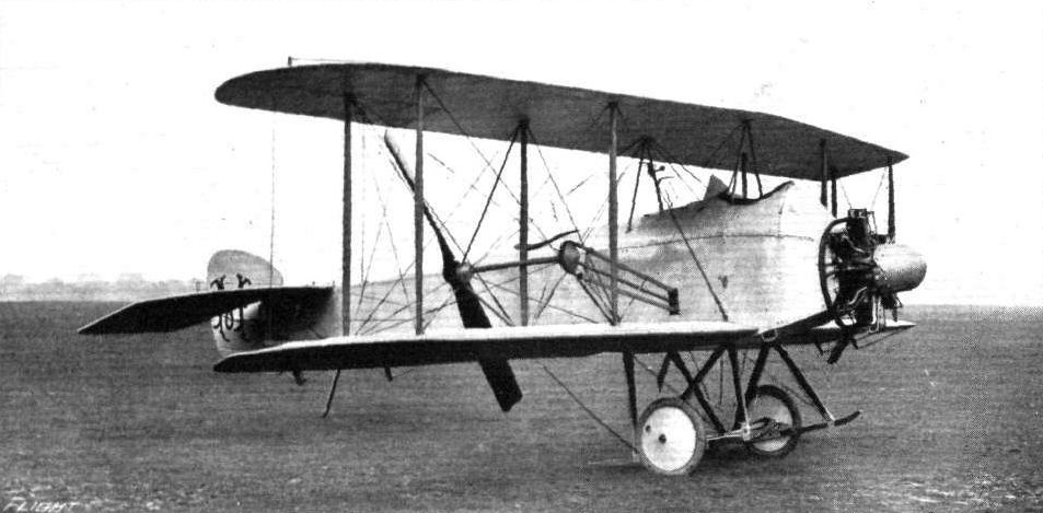
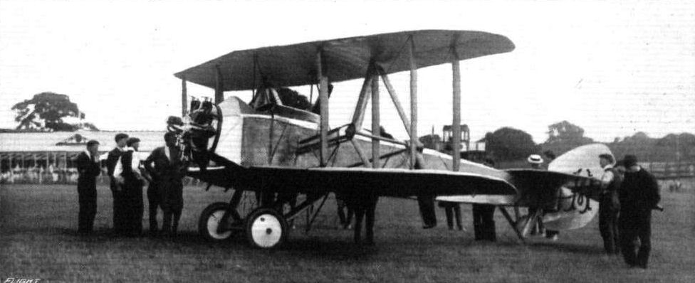
The Mann biplane, with the new landing chassis.
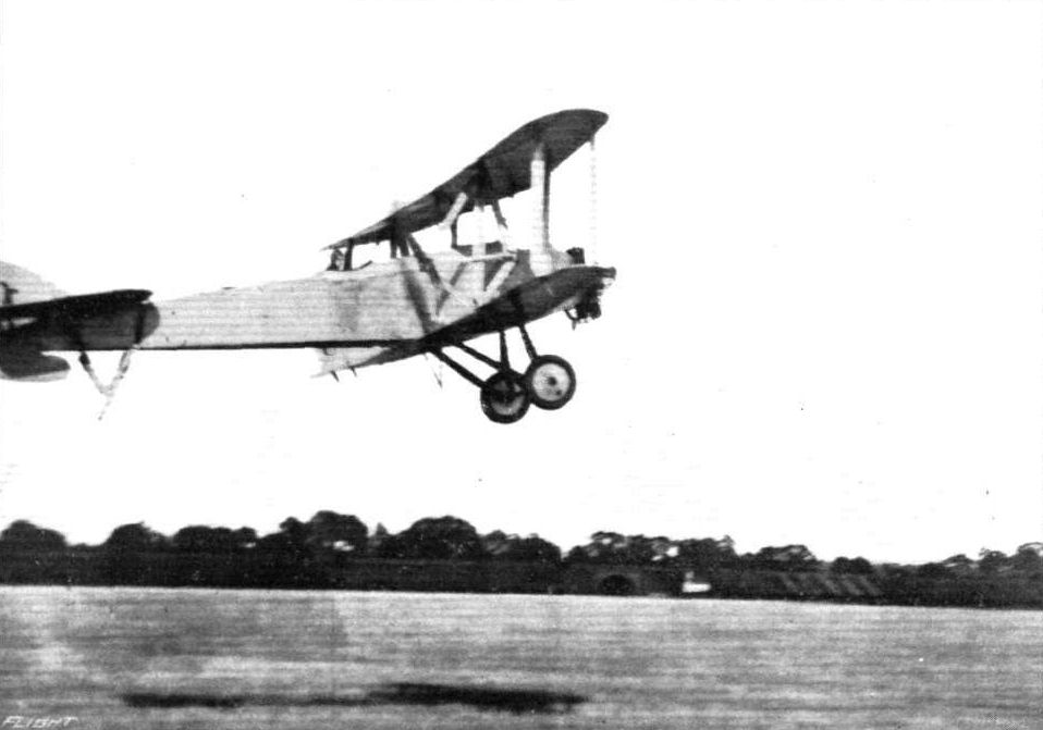
Mr. Rowland Ding just getting off on the Mann biplane.
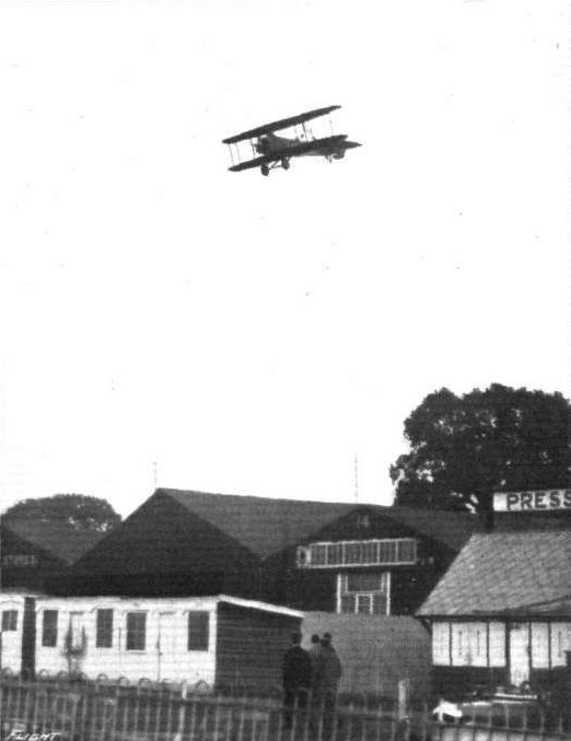
Mr. A. E. Barrs returning on the Mann biplane at Hendon, after having taken her up to an altitude of 5,000 feet.
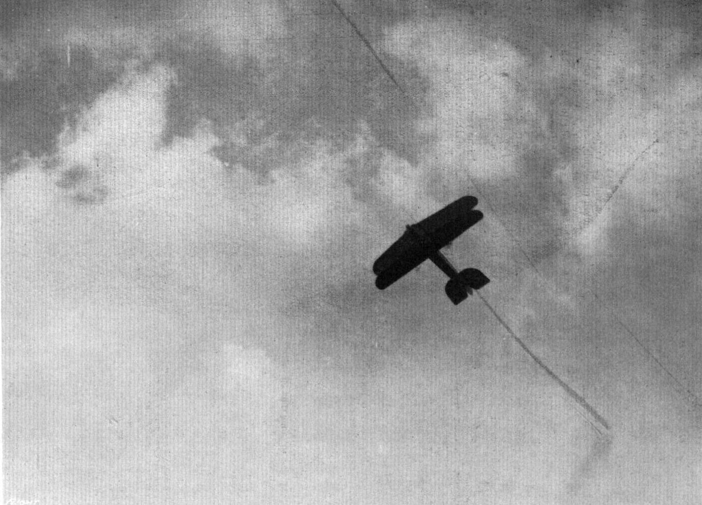
ON THE UPWARD GRADE AT HENDON. - A view from beneath of the Mann biplane.
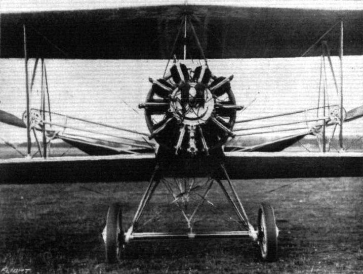
Centre part of the Mann biplane showing the 125 h.p. Anzani engine, as seen from the front.
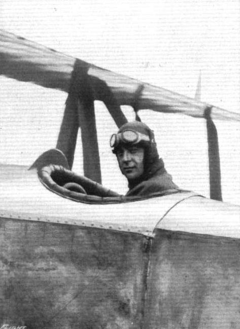
Mr. A. E. Barrs, who is flying the Mann biplane at Hendon.
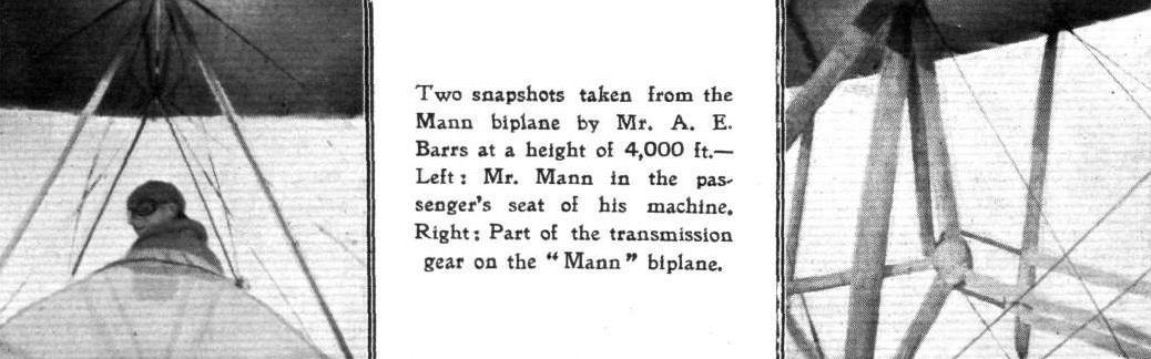
Two snapshots taken from the Mann biplane by Mr. A. E. Barrs at a height of 4,000 ft. - Left s Mr. Mann in the passenger's seat of his machine. Right: Part of the transmission gear on the "Mann" biplane.
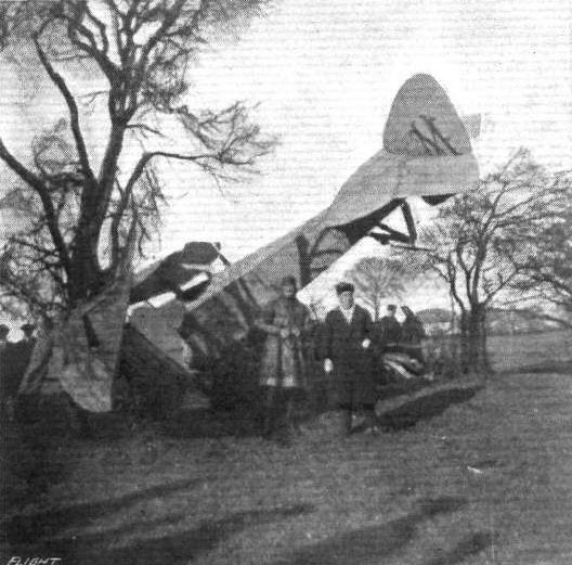
The Mann biplane, after it had decided to stop.
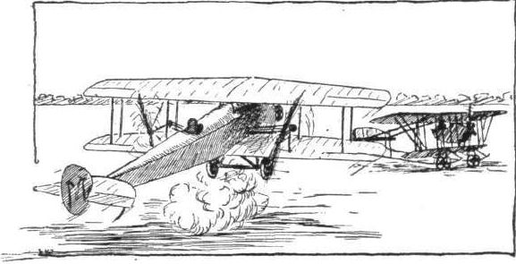
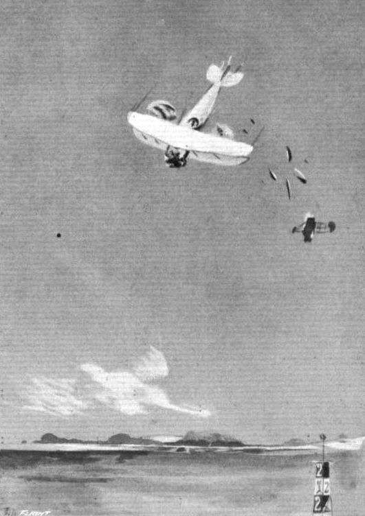
An artist's impression of the incident to the Mann twin-propeller biplane at Hendon.
Flight, October 29, 1915.
CONSTRUCTIONAL DETAILS.-VIII.
<...>
An undercarriage differing entirely from any of the others shown was that of the Martinsyde monoplanes, and which is illustrated in one of the sketches. The weight of the whole machine is taken by a single large diameter steel tube that is built into the body at a point just forward of the centre of gravity. Landing shocks are taken by the tube travelling vertically against the tension of the rubber shock absorbers, the sliding collar guiding the tube on its travel. A skid of hickory, shaped like a hockey stick, extends forward below the propeller to protect it, and is supported in front by a stout ash strut coming down from the body.
<...>
Various types of single-skid undercarriages.
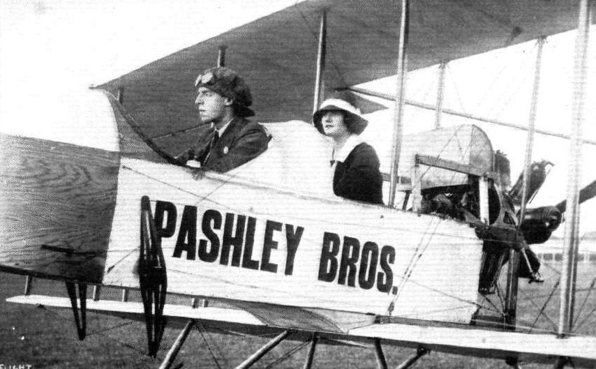
Mr. Clarence Winchester, who has done considerable journalistic work in connection with aviation over the signature of "Ornis," and has just secured his pilot's certificate at the Pashley Flying School, Shoreham. In the passenger's seat is Mr. Winchester's wife, who is as keen on flying as her husband.
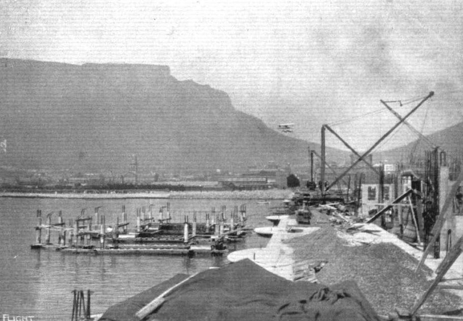
FLYING OVER THE PROMENADE AT CAPE TOWN. - A reminiscence of the work in South Africa of Mr. Compton Paterson.
Flight, November 5, 1915.
A "Christening"' Function at Richmond.
IT is always gratifying to see a newcomer into the Aviation Industry "make good," especially when the initial start was made on a very modest scale. Such is the case of the Whitehead Aviation Company of Richmond, which was formed some months ago and which has, under the able guidance of its managing director, Mr. J. A. Whitehead, done exceptionally well in the way of aeroplane construction under none too favourable conditions. However, by good organisation of the resources available and by taking the best possible advantage of the space at hand this firm has just finished its first machine.
By way of celebrating this event a little informal "christening" ceremony was arranged for Sunday last, at which a number of guests were present. Among those invited were Mr. Lloyd George, the ex-Lord Mayor of London, the Mayor of Richmond, Colonel Maude, Doctor A. Lynch, M.P., Mr. L. Blin Desbleds, and a number of Mr. Whitehead's personal friends. The function was very successful, Mr. Whitehead's little daughter Helene after whom the machine was named, breaking a bottle on the nose of the machine, assisted at the last moment by her father. At the luncheon which followed a telegram was read from Mr. Lloyd George expressing his regret at being unable to attend the ceremony, and some speeches, during the afternoon, in which congratulations were offered to Mr. Whitehead and the firm, helped to wind up a very pleasant gathering of well-wishers to the Whitehead Co. in particular and aviation generally.

Mr. J. A. Whitehead has been "hustling" at his Richmond factory in connection with the Whitehead Aircraft Co. and the building of aeroplanes, a notice of the christening of the first offspring - "Helene" - being given in "FLIGHT" recently. Above are two postcards of a series which Mr. Whitehead is issuing. On the left is Mr. Whitehead himself in the machine with his little child, and on the right is a snap of the first machine in the factory, with some of the work-people who are associated with the Company.
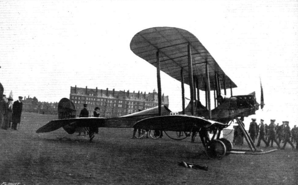
A snap on Folkestone Leas last February, after tbe return of the warplane from a scouting expedition during which the pilot had sighted an enemy submarine. Note the broken wing and propeller.
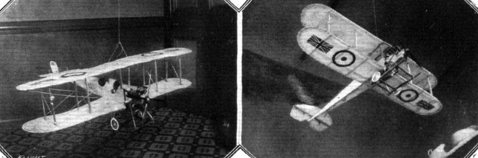
A model oi a B.E. made by a Scotch reader, Mr. Jamies Ditthie.

SCALE MODEL. - A B.E. made by Mr. G. Stuart-Bell.
Flight, June 25, 1915.
FLYING AT HENDON.
LAST Saturday's proceedings opened unofficially with a remarkable demonstration by W. Rowland Ding on a Blackburn-B.E. 2c This machine took the air like a pantomime fairy in the transformation scene, or, to put it in more technical phraseology, like a helicopter. It seemed impossible to stall the machine in the true sense of the word, for when it could climb no more, it - without the aid of the pilot - simply put its nose down and proceeded in a more horizontal attitude. During the afternoon Ding made four other flights, one of which was for the hour test. On this occasion, accompanied by an observer, he reached an altitude of over 10,000 ft., without forcing the machine.
<...>
EDDIES.
When paying a short visit to Hendon on Thursday of last week I happened to witness one of the prettiest, or perhaps I should say two of the prettiest, bits of flying that I have seen for quite a long time. An officer of the R.F.C. was just starting off on a B.E. 2c of the improved type when Mr. Rowland Ding of the Northern Aircraft Co. started out to test one of the latest Blackburn-built B.E. 2c's of the standard type. Ding was the first to get off, and was followed a few seconds later by the other B.E. Climbing rapidly until they had reached a sufficient altitude, the two pilots started a series of spirals and steeply banked turns, in some of which the machines, if they were not actually banking vertically, were at least 89 degs., 59 mins. and 59 secs, from the horizontal.
***
It was a beautiful sight to see the two machines circling round one another in graceful curves. Once they were flying level, practically side by side, and it was quite surprising how little difference there seemed to be between the speeds of the two models, the Blackburn standard B.E. 2c being to all intents and purposes as fast as the other. Whether the fact that Ding was flying solo, while the other machine had two on board, had something to do with the slight difference in speed is a question. At any rate the weight of the passenger would not, it appears to me, slow down the speed to such an appreciable extent. It seems more probable that the R.F.C. pilot's engine was not quite up to the mark, while that of the Blackburn B.E., built by the Rolls-Royce firm by the way, was pulling like a demon. This was never more noticeable than when "getting off.'' The angle at which Ding took her up was simply alarming, but there did not seem to be any tendency to stall. This climbing speed is indeed, under present conditions of war, an asset of very high value; it now only remains to incorporate an equally good horizontal speed. When up at a good height Ding repeatedly overclimbed the machine, which could be seen to hesitate for a moment and then quite suddenly flop her nose down until she was at her proper gliding angle. There can be no doubt about the longitudinal inherent stability of this type, and the lateral stability is evidently equally good, judging from the total absence of side-slipping in the steepest of turns.
In this connection I had an interesting argument with a friend who maintained that it is impossible to make a B.E. 2c side-slip, since, he argues, the machine will, if the rudder is left alone with left-hand warp put on, turn to the left in a circle proportional to the amount of bank. My own idea is that the machine in question can be made to side-slip by the following procedure: Full warp to, say, left, and ruddering to right, gradually returning rudder to central and at the same time pushing elevator lever forward. When the wings are in a nearly vertical position the elevator would, of course, act as a rudder and prevent the tail from swinging outwards, or, in other words, prevent the machine from doing the left-hand turn. The whole experiment, however, is one which I have no particular wish to see carried out in practice, although if attempted at a sufficient altitude it would probably be safe enough, provided that there is no chance of the machine not standing up to the strain.

A Blackburn-built B.E. C 2 machine in flight at Hendon.
NECK AND NECK PAST THE ENCLOSURES AT HENDON. - Mr. J. H. Moore on his biplane, and Blackburn BE.2c.
Mr. J. H. Moore flying at Hendon Aerodrome on his biplane. On the ground a Blackburn B.E.2C just landed.
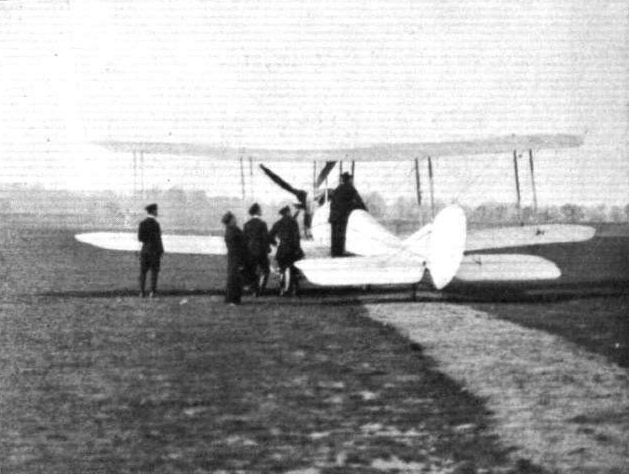
The First Lord of the Admiralty is interested in one of the B.E's.
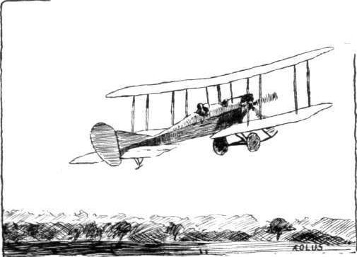

Behind the firing line in France, with a B.E. 2c passing over. From an original drawing by Roderic Hill, who has been invalided home from the trenches, after having been wounded on Hill 70.
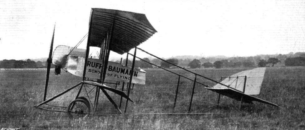
The new 50 h.p. Gnome-Caudron type biplane, built by the Ruffy-Baumann School of Flying, Hendon, and used for tuition and brevet purposes. The same firm are now constructing other machines of similar type of 50 and 60 h.p.
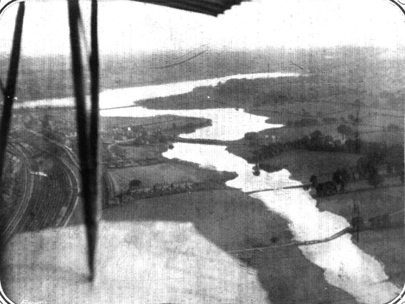
THE WELSH HARP RESERVOIR IN FLOOD AFTER THE RECENT RAINS. - A snapshot from the Ruffy-Baumann biplane at a height of 1,000 ft.

ABOVE HENDON AERODROME. - A snap from the Ruffy-Baumann biplane at 500 ft. above the flying ground. The road seen prominently in the photograph is part of Collindale Avenue.
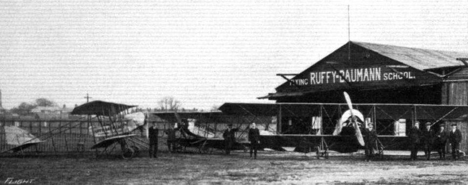
Some of the pupils of the Ruffy-Baumann School of Flying and three of the machines at present in use. This number will shortly be increased as the Works are busy on the production of several biplanes.
Flight, October 22, 1915.
CONSTRUCTIONAL DETAILS.-VII.
<...>
The two examples given of the single axle and single-pairs-of wheels form of undercarriage are similar in type and differ in detail construction only. In the Dyott monoplane the axle runs right across from skid to skid, while in the Sopwith Scout the stub axles are pivoted in the centre, half way between the skids, and move up and down between two transverse members. Bracing of the front portion of the undercarriage is effected in the Dyott machine by a transverse compression member and diagonal cross-bracing, while in the Sopwith there is no such transverse member in front, its place being taken by cables running outwards from the skids to the main planes.
<...>
CONSTRUCTIONAL DETAILS.-VII.
<...>
The two examples given of the single axle and single-pairs-of wheels form of undercarriage are similar in type and differ in detail construction only. In the Dyott monoplane the axle runs right across from skid to skid, while in the Sopwith Scout the stub axles are pivoted in the centre, half way between the skids, and move up and down between two transverse members. Bracing of the front portion of the undercarriage is effected in the Dyott machine by a transverse compression member and diagonal cross-bracing, while in the Sopwith there is no such transverse member in front, its place being taken by cables running outwards from the skids to the main planes.
<...>
Various types of double skid undercarriages.
Flight, March 26, 1915.
EDDIES.
For the space of a few minutes it was quite like old times up at Hendon on Saturday last, when Hawker, who had arrived from "somewhere" on a new Sopwith two-seater tractor biplane, circled the course several times, banking round the pylons in a way to gladden the hearts of everyone who appreciates skilful piloting. Later in the afternoon Hawker gave another demonstration of his art by taking the big Sopwith gun-'bus out for several circuits over the surrounding country. His handling of this machine was simply superb, everyone looking on in amazement. Some even began to figure out that it must be an entirely new machine, as it had never before been known to fly at such a speed, or to climb so steeply, or to do such sharp banked turns. But it wasn't - it just meant that Hawker is able to bring out the very best points of a machine, and to get out of it every ounce that it is capable of. At one time Hawker on the Sopwith gun-'bus and Mr. de Havilland on the De H. I., were flying almost side by side, their speeds seeming practically even, and as the De Havilland does over 70 miles an hour, the speed of the Sopwith - when piloted by Hawker - must be pretty well the same.
Flight, November 12, 1915.
CONSTRUCTIONAL DETAILS.-X.
<...>
In the Sopwith undercarriage illustrated the same simplicity prevails. Here, however, the axle is divided in the centre, where it is pivoted between the two transverse members joining the apexes of the chassis struts. In order to prevent a downward movement of the centre of these members a single wire is taken from this point to the bottom of the body. Transverse rigidity is established by diagonal cross bracing between the front pair of chassis struts as shown in the sketch. This undercarriage, it should be pointed out, is not that fitted as standard on the Sopwith scouts. It was, in fact, quickly produced for the last Aerial Derby, the original chassis of these machines being of the double-skid type. Since then other types have been experimented with, among these being one with no shock absorbers, but having wheels fitted with large diameter pneumatic tyres.
<...>

The finish of an hour's Admiralty test. Mr. Hawker returning to Hendon on a Sopwith tractor.

Various "Vee"-type undercarriages constructed of wood.
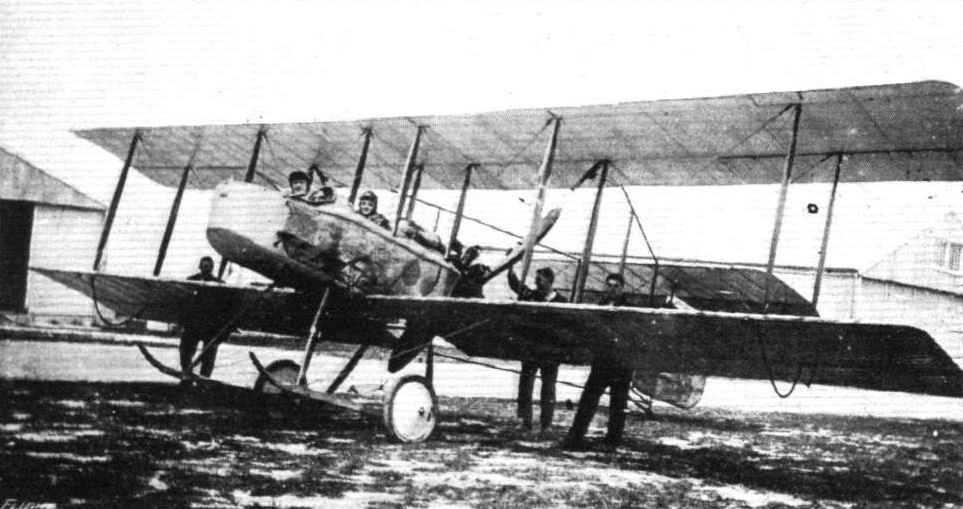
A 100 h. p. Vickers gun 'bus, reproduced from a photo, taken somewhere on earth by a reader of "FLIGHT."
Flight, November 5, 1915.
CONSTRUCTIONAL DETAILS.-IX.
<...>
The remaining two illustrations show the undercarriages of the Vickers scout and Ponnier monoplane. In the Vickers chassis the wheels are sprung, as shown in the sketches, whereas in the Ponnier no springing whatever is provided except that afforded by the pneumatic tyres. This last type of undercarriage may probably be said to be as simple as it is possible to make an undercarriage, and would be of little use on rough ground. It was, as a matter of fact, used on the machine flown by Emile Vedrines in the last Gordon-Bennett race at Rheims.
Various undercarriages of the "Vee" type.
Flight, November 12, 1915.
FLYING AT HENDON.
<...>
The second incident was the flying visit of an unknown pilot on a chunk of greased lightning disguised as a scout-biplane. He suddenly appeared over the aerodrome, descended to a few hundred feet, and executed two of the finest loops I have ever seen. They were not only perfectly clean and in rapid succession, but the machine climbed on each loop in a remarkable manner. He then gave us a display of speed and "vertical" climbs, executed another loop starting at a height of about 250 feet, and then vanished! Some wizard! Even Louis Noel, who has had the opportunity of witnessing many types of "extra special" war-planes in flight, expressed a most enthusiastic opinion on the whole performance. It was, he said, the fastest 'bus he had seen, and asked me to convey to the pilot and designer his congratulations, which I take the opportunity of doing here. We managed during the stranger's passing over to secure a good snap of him right way up, and also at the moment of his chassis facing the heavens. We are hoping to publish these unique photos; but if they are censored for the moment - well, later on they will be just as interesting.
<...>
EDDIES.
During Noel's visit to Hendon on Saturday, he had an opportunity of admiring some of the new British machines that have sprung into existence since he left for France at the beginning of the war. Most interesting among these was, perhaps, that of the unknown pilot who, I hear, appeared suddenly from nowhere in particular, circled the aerodrome a few times, executed a succession of loops of a most extraordinary character, and disappeared as suddenly as he came, nobody knew whither. Who the stranger was I am not in a position to tell, as I did not happen to be at Hendon at the time, but from the descriptions of the machine and the astounding speed at which she was apparently travelling, I am inclined to hazard the opinion that it was none other than our old friend Harold Barnwell on a Vickers scout. Still, not having been there myself, I cannot guarantee the accuracy of this surmise. But it was "some" scout without a "possible probable doubt."
AT HENDON - A STRANGER MAKES A "COURTESY" CALL. - The machines in the air are: top, Vickers scout flown by Mr. Harold Barnwell; and below, a Grahame-White biplane. Inset at the top, left, is the Vickers scout witl its chassis heavenwards, during one of the loops which it made upon its "courtesy" call at Hendon, and to which reference was made in "Eddies" and Hendon Notes last week.
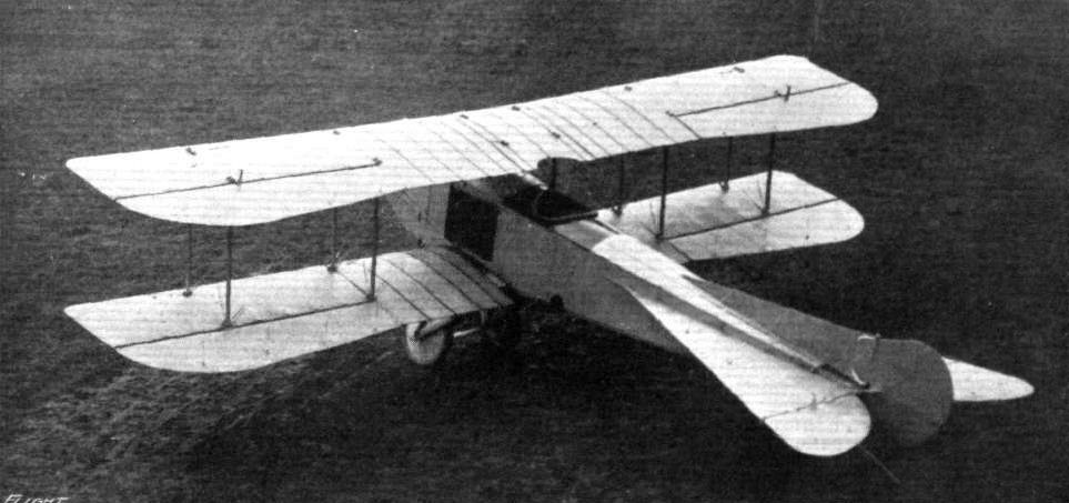
The "Reo" biplane which has just been completed, and is now ready to be tested at Hendon. The trial flights are expected to take place during the next few days.

Scale model by Eric L. Wright, one-sixteenth full size of the Wight seaplane, exhibited at the last Royal Aero Show at Olympia on Messrs. J. Samuel White and Co.'s stand.
Flight, March 5, 1915.
THE A.E.G. MONOPLANE FLYING BOAT.
IN our issue of September last and following issues we gave a series of illustrated descriptions of various German seaplanes, among which was, it may be remembered, the A.E.G. tractor seaplane. Particulars are now to hand of a monoplane flying boat built by the same firm and entered for the Warnemunde Scandinavia Seaplane Race, which was postponed on account of the war.
The aeroplane portion of the A.E.G. flying boat consists, as will be seen from our illustration, of a pair of monoplane wings having slightly back-swept and upturned wing tips after the fashion somewhat of the Taube land machines. The upturned tips are not, however, extensions of the framework of the main planes, but take the form of hinged ailerons and serve to maintain lateral stability. The wings are built up of wooden ribs over steel tube spars. Instead of the cable bracing usually associated with machines of the monoplane type, there is in the A.E.G. a sub-structure in the form of a girder underneath the wings. On each side two booms, which are virtually steel tubes, run from the gunwales of the boat to a point some distance inside the wing tips. In order to keep them clear of the water these booms slope upwards towards the outer ends, where are carried the wing tip floats to which reference will be made later.
From the booms streamline steel tube struts run to points on the front and rear spars of the main planes, to which they are secured by means of the ball and socket joint that forms the subject of one of the accompanying illustrations. The strut, it will be seen, terminates in a spherical head which fits into the conical socket on the wing spar or outrigger booms, as the case may be. This head has cut through it a slot tapering towards the centre of the ball, where it accommodates a small bolt passing through the sides of the conical socket. In one direction the ball, and with it the strut, may be oscillated through a large arc, as the ball is in this plane concentric with the bolt. On the other hand, the tapering slot allows of moving the strut in the opposite direction through an angle proportionate to the length of the tapering slot in the ball. The conical socket is enclosed on two sides by a steel plate which passes round the spar or outrigger, to which it is secured by welding. It is thus possible to mount the strut at a variety of different angles, which is an advantage for experimental purposes when it is desired to find the most favourable position for the wing tip floats, and also facilitates folding the wings for transport or storage.
These floats are mounted flexibly on the outer ends of the outrigger booms by means of rubber bands taken round extensions of the booms and round four steel tube fittings having the shape of an inverted U and secured to the top of the floats. Additional springing is provided by the spring boards mounted underneath the flat bottom of the floats. Mounted on a strong structure of streamline steel tubes running down to the centre of the boat is the engine - a 150 h.p. Benz - which is totally enclosed on the sides by an aluminium and fabric housing attached to the inner ribs of the main planes. In front of this housing is mounted the radiator, whilst the rear is left uncovered to facilitate the escape of the air and exhaust gases. Inside the housing, between the radiator and engine, are mounted two small tanks, one of which contains the lubricating oil, whilst the other is the petrol service tank. The main supply of petrol is carried in a larger tank placed down inside the boat behind the seats. A cabane of steel tubes rests on the struts carrying the engine and run up through the engine housing, through the roof of which it projects slightly. Two large rings or eye bolts at the upper end of the cabane members serve to receive the hooks of two strong cables, by means of which the whole machine can be lifted out of the water.
The main float or boat is of the single step type, and runs to a point in the bow, while at the stern it terminates in a vertical knife edge. The portion of the boat bottom in front of the step is V-shaped near the nose, flattening out gradually towards the step, where it becomes quite flat. The rear part of the boat from the step to the stern is perfectly flat-bottomed. Inside the cockpit, which is situated just ahead of the front engine struts, are arranged the two seats, the occupants of which are protected from water spray and wind by the curved front portion of the deck. Six bulkheads divide the boat into seven water-tight compartments, the first bulkhead occurring in front of the cockpit, the second one behind the cockpit, between it and the compartment containing the main petrol tank; the third one occurs immediately over the step, and the remaining ones are placed at regular intervals back to the stern. At the rear, mounted on a somewhat frail-looking structure of steel tubes, are the tail planes, which consist of an approximately triangular shaped fixed horizontal plane, to which is hinged the undivided elevator, surmounted by a vertical fin, to the rear edge of which is hinged the rudder.

The A.E.G. flying boat starting for a flight.
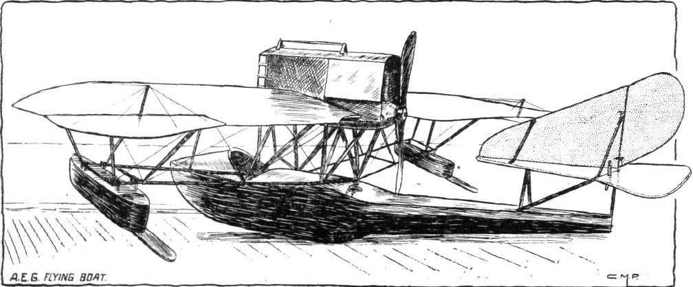
The new German A.E.G. flying boat, built just before the commencement of the War.
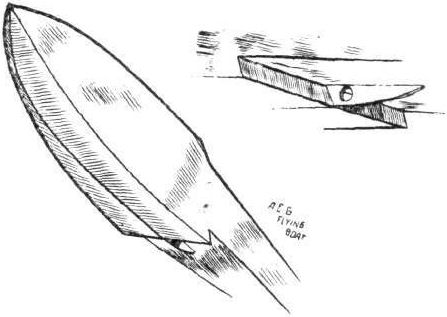
View from underneath of the front portion of the boat, and rear view of step.

The ball and socket strut joint employed in the A.E.G. flying boat.
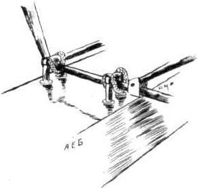
Sketch showing suspension of wing tip floats.
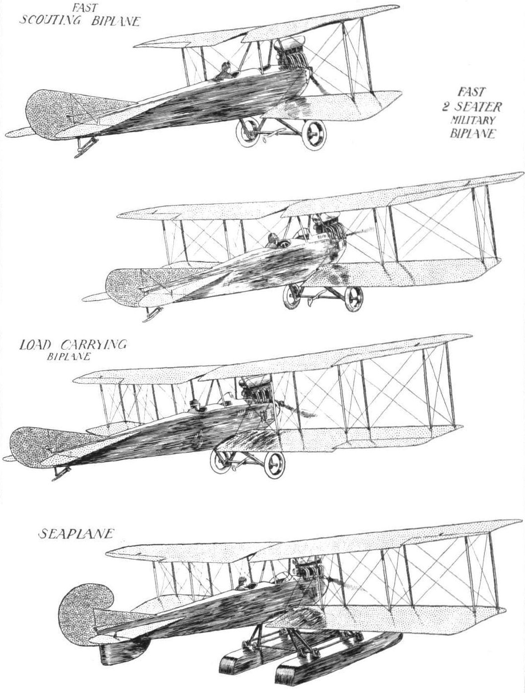
FUSELAGE ECONOMY. - Four members of the Albatros family, all of which are fitted with the same size fuselage. In this manner three different types of land machines can be provided simply by substituting wings of various sizes, whilst the larger size machine is turned into a seaplane by fitting floats instead of the usual undercarriage.
FUSELAGE ECONOMY. - Four members of the Albatros family, all of which are fitted with the same size fuselage. In this manner three different types of land machines can be provided simply by substituting wings of various sizes, whilst the larger size machine is turned into a seaplane by fitting floats instead of the usual undercarriage.
FUSELAGE ECONOMY. - Four members of the Albatros family, all of which are fitted with the same size fuselage. In this manner three different types of land machines can be provided simply by substituting wings of various sizes, whilst the larger size machine is turned into a seaplane by fitting floats instead of the usual undercarriage.
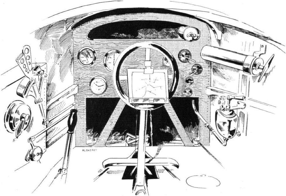
Sketch showing the very complete set of instruments carried on the captured German Albatros reconnaissance biplane.
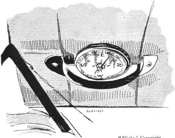
The compass has been mounted in a somewhat unusual fashion on the Albatros biplane, as shown in the sketch. It is placed in the inner portion of the top plane, where it can be seen by both pilot and observer.
FUSELAGE ECONOMY. - Four members of the Albatros family, all of which are fitted with the same size fuselage. In this manner three different types of land machines can be provided simply by substituting wings of various sizes, whilst the larger size machine is turned into a seaplane by fitting floats instead of the usual undercarriage.

In one of the captured Albatros biplanes the petrol service tank is mounted on top of the upper plane. As will be seen from the sketch, it is fitted with the usual gauge for indicating the amount of petrol in the tank.

Inspection door for the aileron cable pulley on the Albatros biplane.
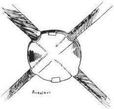
The bracing cables of the captured Albatros biplanes are held together by the neat little clips shown in the accompanying sketch. In earlier models of these and other German machines small slotted rubber or fibre balls were used for this purpose.
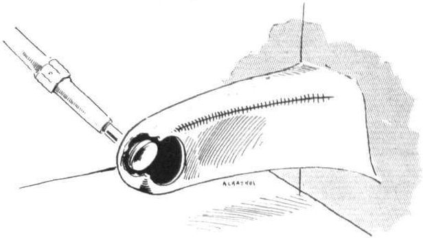
Rudder and elevator crank levers of the Albatros biplane.
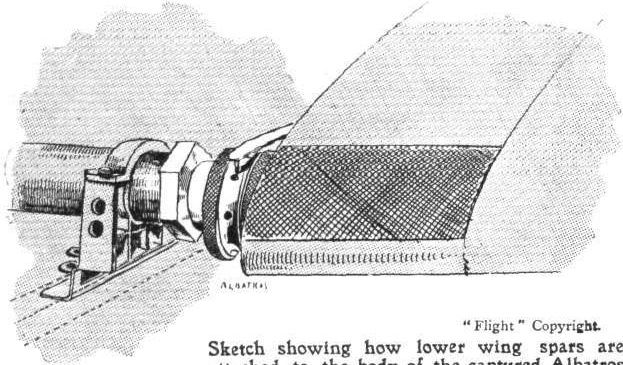
Sketch showing how lower wing spars are attached to the body of the captured Albatros biplane.
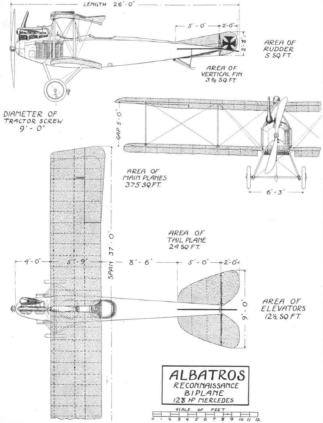
THE CAPTURED ALBATROS BIPLANE. - Plan, side and front elevations to scale.
Flight, November 26, 1915.
THE CAPTURED ALBATROS RECONNAISSANCE BIPLANE.
OF the three captured German aeroplanes that have been for the last couple of weeks on view on the Horse Guards Parade the smaller of the two Albatros biplanes is, perhaps, the more interesting, seeing that it is of a later type than the larger fighting biplane of the same make. The majority of our readers will already be familiar with the general design and construction of the Albatros machines from the description given in our issue of April 4th, 1914, of the biplane flown over here by the well-known pilot Robert Thelen.
In its general arrangement the reconnaissance type, which is evidently a fairly recent model, does not differ to any great extent from the larger machine seen at Hendon last year, but numerous details have been altered and improved as a result, no doubt, of the lessons learned since then in actual warfare. One of the chief characteristics of the older machine - namely, that of building up the fuselage without the use of wire bracing - has been retained, so that it would appear that this form of construction has stood the test of time. The main framework of the Albatros fuselage consists of six longitudinals, of which the two lower ones are ash and the rest spruce. At intervals of a couple of feet these longitudinals are connected by struts and cross members, swelled out where they pass the longitudinals and abutting with their ends on small angle pieces, also of wood, the latter surrounding the two inner sides of the longitudinals. Instead of the usual wire bracing, rigidity is obtained by a covering of three-ply wood screwed to the longitudinals, a form of construction which was criticised by several experts at the time of the visit by the first Albatros, but which nevertheless seems to have stood up to the hard usage of aerial warfare in a satisfactory manner.
In the stern the body flattens out to a horizontal knife-edge, somewhat after the manner of the Morane monoplanes. In order to strengthen the body at its shallowest part, and also to furnish a rigid support for the steel tube that serves as a pivot for the rudder, a short keel-like fin made of wood runs along the bottom of the body from the stern forward to the tail skid supports. Seen from the rear this keel is shaped like a T with the angles between its vertical and horizontal members rounded off. A turtle back runs along the entire top of the body, its highest point being just front of the observer's seat.
Mounted on two stout longitudinal bearers, which are in turn supported on transverse members of ply wood, is the 128 h.p. Mercedes engine, in the general design of which no radical alterations appear to have been made. The usual Bosch hand-operated starting magneto is fitted so that, after swinging the propeller to draw a charge into the cylinders, the mechanic can get out of the way leaving the actual starting of the engine to the pilot.
As in the larger machine flown by Thelen the two seats of the reconnaissance biplane are placed in tandem, with the observer in front. To the left of the observer's seat and in the floor-boards of the body is a circular opening closed by a trap door through which evidently bombs are dropped. In front of the observer is mounted a wireless transmitter, current for which is furnished by a small generator mounted on the front right-hand chassis strut. The generator for the wireless set, instead of being driven from the engine, was driven by a small propeller, or, more correctly speaking, from a windmill shaped like a two-bladed propeller. The antenna of the wireless set takes the form of a stranded copper cable passing from the observer's cockpit through a short copper tube with a bell mouth. At its lower end this antenna is weighted with a piece of lead so as to prevent it from being blown straight back by the force of the wind. When nearing the ground the observer winds the copper cable up to prevent it catching in obstacles when making a landing.
On the dash in front of the pilot are mounted a number of instruments, including the Bosch starter, double switch for switching on the ordinary magnetoes once the engine has started on the hand-operated magneto, throttle and spark levers, petrol gauge, revolution indicator, manometer, tell-tale glass and pressure pump, clock, altimeter, and last, but by no means least, a Clift air speed indicator. The compass, instead of being mounted in front of the pilot as is usually the case, is built into the top plane in a position where it can be seen by both pilot and observer. The accompanying sketch will explain the placing. The controls are the usual ones, and consist of a wheel for the elevator and ailerons and a pivoted foot bar for the rudder. One of the reasons why some pilots prefer the single lever control, or "stick" as it is termed in aviation parlance, is that the wheel tends to interfere with the reading of the map. This difficulty has been overcome in the Albatros by placing the map-holder on the wheel itself in the manner shown in one of our sketches. Behind the pilot's seat is a large fabric bag evidently intended for despatches. In order to improve the view in a downward direction obtainable from the pilot's seat the trailing edge of the lower wing has been cut away near the body.
Petrol is carried in a main tank placed under the observers seat, and the fuel is forced by a pressure pump to the little streamline service tank mounted on top of the upper wing, whence petrol is gravity-fed to the carburettors. Filling the main tank is accomplished through a little circular door in the right-hand side of the body.
On each side of the body is mounted a radiator of a type that is very popular in Germany. It is, we believe, known over there as the Hazet radiator, and its chief claim to notice is that it is built up in sections, and that therefore by adding or taking away one or more sections any size engine or any climatic conditions can be suited. The two tubes, placed top and bottom respect ively, which connect the various sections of the radiator are parallel with the sides of the body, and each section of the radiator is therefore set at an angle of the tubes so as to bring them into the line of flight. An examination of the accompanying illustrations will show the general arrangement.
In section and general construction, the wings of the reconnaissance type biplane are similar to those of the large machine seen at Hendon last year. The span, however, is a good deal shorter, and there are only two pairs of inter-plane struts on each side instead of the three with which the older machine was fitted. We have before now referred in our columns to the practice of the Albatros firm of having three sets of wings for each fuselage, one large pair with three pairs of inter-plane struts on each side, for weight-carrying and duration flights, one pair a little shorter with two pairs of struts a side, and a small pair with only one pair of struts on each side, for using the machine as a fast single-seater scout.
The inter-plane struts are streamline steel tubes tapering towards the ends, where they fit into eyebolts going through the main spars. The method of attaching the bracing cables is identical with that employed on the older machine, and which was illustrated in our issue of April 4th, 1914. A steel shell rests on a fibre pad that is shaped to fit the curvature of the plane. Inside this shell is earned a steel ring to which are attached the turnbuckles of the bracing cables. The two main spars of the wings are placed comparatively close together, giving a rather great amount of unsupported trailing edge. A short distance behind the main rear spar is another spar, or perhaps it would be more to the point to call it a former since none of the bracing cables are attached to it, forming at its outer portion a support for the aileron hinges. The ailerons, fitted to the top plane only, are given an upward turn towards the tip so as to make their outer ends meet the air at a negative angle of incidence, an arrangement which appears to have been chosen with a view to rendering the ailerons more efficient inasmuch as the one on the high side is already having a depressing effect when in its normal position, increased immediately as soon as the aileron in question is moved upwards, while with the ordinary form the aileron has to move first up to the angle of no lift and then still further in order to meet the air at a negative angle of incidence. The method of operating the ailerons differs from that usually employed over here in that the crank levers are horizontal, working in a slot in the upper plane. The control cables pass from the drum on the column round pulleys mounted on the floor in front of the foot-bar to pulleys inside the wings and near the end of the lower plane. Hence the cable passes to the aileron, whilst the return or equalising cable runs to the aileron crank lever.
The two halves of the upper plane are attached to a cabane of steel tubes bolted with their lower ends to the upper longitudinals of the body. The main spars of the lower plane are secured to the fuselage in the manner shown in one of the accompanying sketches.
The tail planes present no novelties either aerodynamically or constructionally. There is the usual flat tail plane or stabiliser to which is hinged the divided elevator. On top of the fuselage is a triangular fin, to which is hinged the rudder. The crank levers, operating elevator and rudder are rather neatly designed having at their outer ends a concave socket into which fits the hemispherical head of the turnbuckle.
The undercarriage is of the simple "Vee" type, having streamline steel struts that fit with their upper ends into sockets on the lower longitudinals of the body. The apexes of the two "Vees" are connected by a transverse tube, and the tubular axle rests in the angle between the struts. The rubber shock absorbers are wound around the apex of the "Vees" and are protected against contact with the ground by leather guards strapped to the struts and passing underneath the shock absorbers. No radius rods are provided, but the movement of the axle is restricted by a short length of stranded cable on each side running from the front to the rear chassis strut. Pivoted on the centre of the axle is a brake similar to that with which Thelen's machine was fitted. This brake, which has a claw shaped somewhat like a plough-share is operated through a cable by a lever placed to the left of the pilot's seat. When wishing to bring the machine to a stand-still, the pilot pulls this lever towards him against the action of spring, and the claw digs into the ground checking the speed of the machine very quickly, but tearing up the ground in a comprehensive manner that would exclude the use of the brake when landing on such unmilitary grounds as parks and cricket grounds. If, however, there is no objection to doing a little ploughing, the brake is highly effective in pulling up the machine. A small tail skid sprung with rubber cord protects the tail planes when making a landing. We regret that we have been unable to obtain any figures regarding the weight and speed of the Albatros reconnaissance biplane.
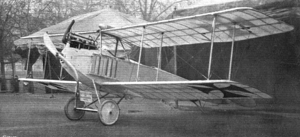
Three-quarter front view of the captured Albatros biplane.
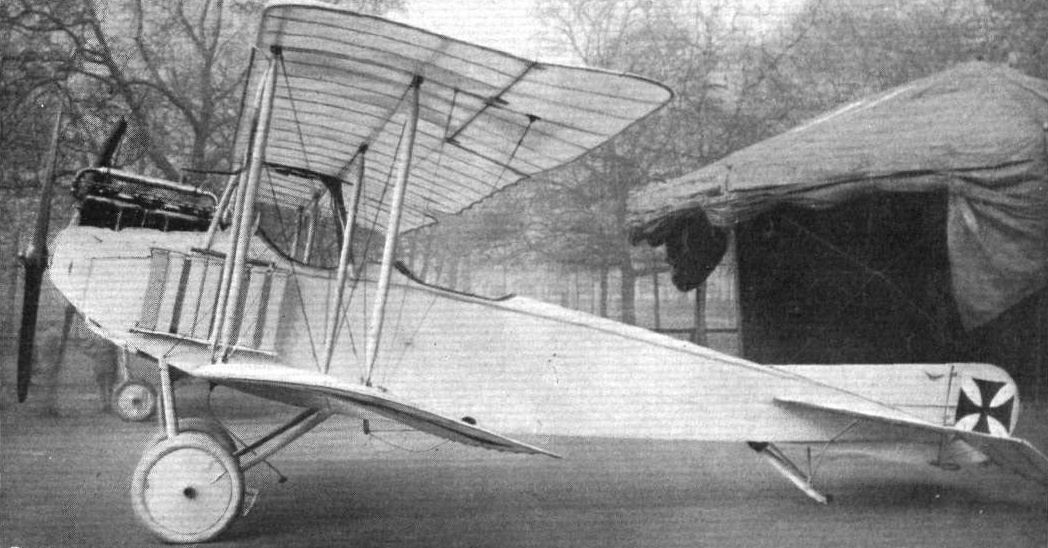
Side view of the captured Albatros biplane.
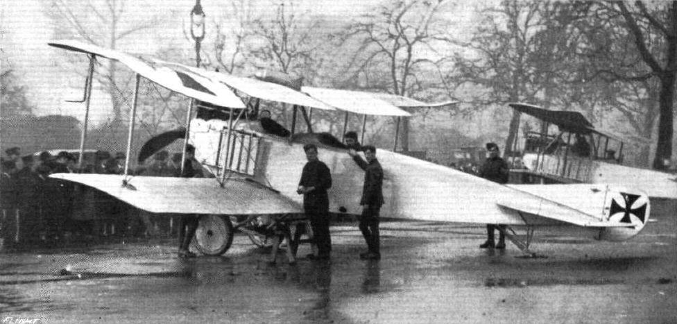
ANOTHER "PRISONER OF WAR." - A German Albatros scout which was forced to appears to descend, but which have almost entirely escaped damage by our shells.
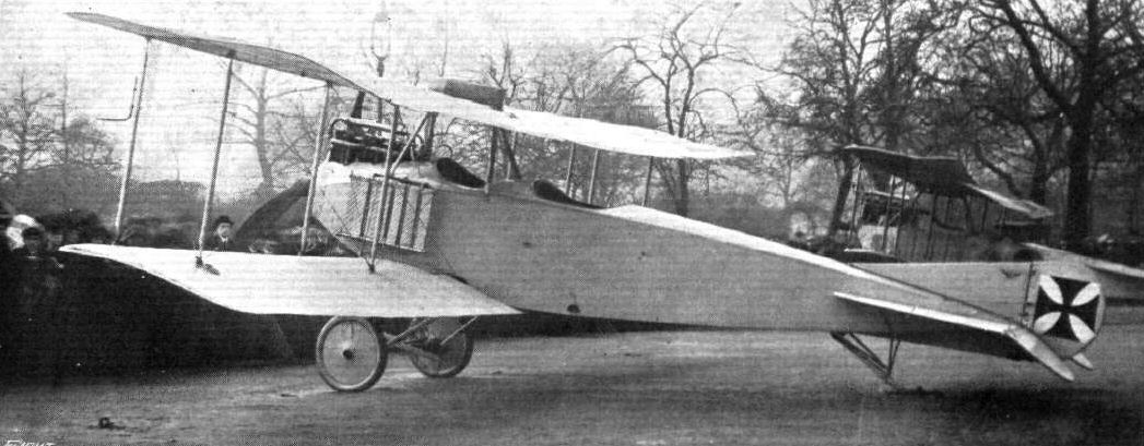
Three-quarter rear view of the Albatros biplane.

Chassis and engine of the Albatros two-seater reconnaissance biplane.
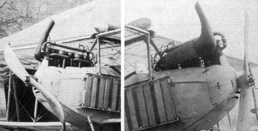
The smaller Mercedes engine, rated at 128 h.p., on the Albatros two-seater reconnaissance biplane on the Horse Guards Parade.
Flight, December 24, 1915.
THE CAPTURED ALBATROS FIGHTING BIPLANE
HAVING been designed to carry a fairly heavy machinegun and a considerable amount of ammunition the captured fighting type Albatros that was exhibited on the Horse Guards' Parade is naturally of somewhat larger dimensions than was the two-seater Reconnaissance type of the same make described in our issue of November 26th.
Generally speaking, however, it does not differ greatly in detail construction from the smaller machine, the wing design and construction as well as the method of building up the fuselage without the use of cross-wiring being practically identical in both cases. Being intended for fighting rather than for scouting purposes climbing capacity has been aimed at rather than high speed in horizontal flight. The deeply cambered wings - as cornpared with those of the majority of British machines - set at a comparatively great angle of incidence, are evidently capable of raising a great load even at low speeds.
As the body construction is of a form not usually seen in this country, a few words regarding it may be of interest. In addition to the four main longerons situated in the four corners of the rectangular section fuselage, there are two more, one half-way up on each side. As no wire bracing is employed, the attachment of struts and cross-members to the longitudinals becomes a fairly simple matter. As far as it was possible to ascertain, this joint consists simply of a "knee" piece of hard wood resting on the two inner surfaces of the longeron, and secured by screws through the three-ply covering. The struts and cross-members appeared be simply abutting against this "knee" but were probably in reality mortised or dowelled. Where the middle longeron crossed the struts these were swelled out in the manner shown in the sketch, and further strengthened by three-ply wood as illustrated.
As regards the strength of this method of construction, we were shown, at the time of the first visit by an Albatros biplane to this country in 1914, a testimonial from the Deutsche Versuchsanstalt fur Luftfahrt to the effect that this institute had examined and corrected the calculations made by the Albatros firm, and that the body of the Albatros biplane had a factor of safety of about 60. The Versuchsanstalt further stated that the bending resistance of a body of this type is 2.5 times greater than that of a cross-wired fuselage of the same outside dimensions, and having members of the size usually employed in the girder type of body. Compared weight for weight the Versuchsanstalt state that the Albatros firm are justified in claiming that the veneer type is the stronger of the two - by how much is not stated. Apart from the questions of strength and cost - although the latter should not count for a great deal at a time like the present - the Albatros form of construction might probably, at least so it appears to us, offer certain advantages for military machines in case of damage by shell fire. If one of the longitudinal members of a girder type body were hit by a bullet or fragment of shell and fractured the strength of the whole structure would be seriously impaired, since the component parts are so greatly interdependent one upon the other. The fracture of the corresponding member of an Albatros type of body would probably not be such a serious matter, since there would be a good deal of rigidity left in the three-ply covering. Experiments made with bodies of each type and of similar weight, purposely damaged and subsequently subjected to an equal amount of loading, should furnish some interesting data on this subject.
Apart from variations in dimensions and engine power, the fighting type Albatros biplane differs from the reconnaissance machine in that the pilot occupies the front seat, while the observer, or more correctly speaking the gunner, is installed in the rear cock pit, where he obtains a better view and is less restricted as regards the number of directions in which the machine-gun can be effectively operated. In order to facilitate gun-laying, the circular "rim" to the rear cockpit takes the form of a turntable, on one side of which is fitted an adjustable gun-mounting of the type shown in the accompanying sketches. By rotating the turntable the gun is trained approximately, in a transverse sense, on the object aimed at, while the final sighting - vertically as well as laterally - is made possible by the universal mounting of the gun on the turntable. In addition to the pivot provided for vertical sighting, the gun may be slightly raised or lowered bodily by means of the parallelogram shown in the sketches, which is locked in any desired position by a short lever. When in its lowest position the weight of the gun is taken by a short laminated spring. A pivoted seat of the piano-stool type is provided for the gunner, and allows him of turning about in an instant to take advantage of any favourable position that may present itself.
The front cockpit is fitted up in the usual way with all the instruments for navigation, &c, and with hand-wheel control for elevators and ailerons, and a pivoted foot bar for the rudder.
As regards the engine - a 160 h.p. Mercedes - this has already been dealt with in a separate article, and there is therefore, no need to go into details here. It will be sufficient to mention that it is mounted on two stout longitudinal members of pine, which are in turn supported in the nose of the machine by the front cross-member of the fuselage, and at equal distances of their length by transverse panels of approximately 1-inch thickness made of multi-ply wood built up of 8-10 laminations, and lightened in the manner shown in the accompanying sketch.
The service tank, which in the particular machine captured appears to have been instrumental in forcing it to come down, since it was pierced in two places by some large projectile, is mounted underneath the upper plane, petrol being forced by pressure from the main tank.
A large exhaust collector or silencer is mounted on the right-hand side of the body, an exhaust pipe running back to a point behind the rear seat, so as to keep the occupants clear of the fumes.
The radiator, which is of the Hazet type, is similar to that fitted on the reconnaissance machine, with the exception that it has ten sections on each side as against the seven sections a side of the latter. This difference in size of radiator is, of course, accounted for by the difference in horse-power of the engines, one being of 120 h.p. and the other of 160 h.p.
Being of an older type than the reconnaissance biplane, the fighting machine does not present anything new in the way of detail constructions, which follow, as a matter of fact, closely on the lines of the large span biplane flown by Thelm at Hendon in 1914.
The main planes are of the usual Albatros type, with the main spars comparatively close together, leaving a deep trailing edge. One alteration is to be found in the trailing edge, which in the machine under review is double surfaced throughout, and not, as in the 1914 type, single surfaced for the last foot or so.
As in previous machines of this make, the undercarriage is of the "Vee" type, with four struts of streamline steel tubes filled with wood. The axle carrying the two large diameter disc wheels is of generous proportions, being some 2 1/2 ins. in diameter. Such a heavy tube has, of course, been necessitated partly by the great weight of the machine and partly by the fact that it serves as a pivot for the claw brake seen in the illustrations.
The tail planes are somewhat different in shape from those of the usual Albatros machine, and are, it will be seen, of large dimensions, especially as regards the fixed horizontal tail plane. It seems probable that the object of this large stabiliser, the angle of incidence of which is adjustable (not in flight), is to preserve the longitudinal stability of the machine when flying with or without a gun and ammunition on board.

Three-quarter rear view of the Albatros fighting biplane.
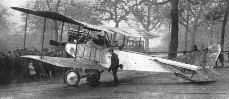
One of the German trophies of war that have been on view for the past week at the Horse Guards' Parade. An Albatros biplane (Mercedes engine) which has been rather severely "strafed" by our boys at the front.
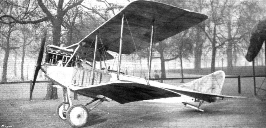
Three-quarter front view of the captured Albatros biplane.
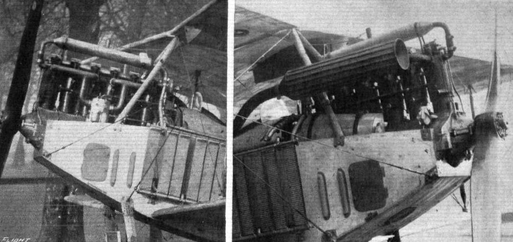
The 160 h.p. Mercedes engine on the captured German Albatros fighting biplane, on view at the Horse Guards Parade.

Engine and chassis of the captured Albatros fighting biplane.
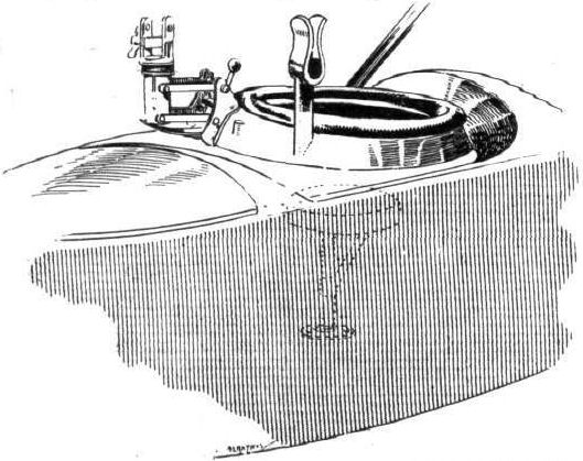
Turntable and gun mounting on the Albatros fighting biplane.
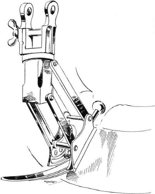
The swivelling mounting for the gun on the captured Albatros biplane.
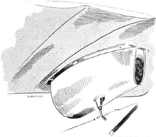
The petrol service tank is mounted underneath the top plane in the Albatros fighting biplane,
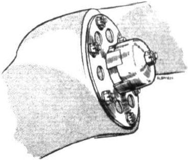
Sketch showing how propeller is locked on its shaft in the Albatros fighting biplane.
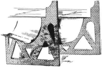
Two of the ply-wood engine bearers on the Albatros biplane.
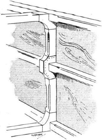
Detail of Albatros fuselage construction.
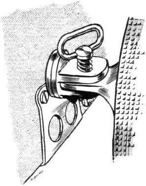
Attachment of lower plane to body of the Albatros fighting biplane.
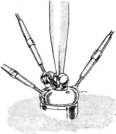
Inter-plane strut joint on the Albatros fighting biplane.
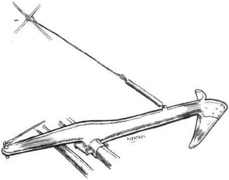
The hand-operated claw brake fitted on all Albatros biplanes.
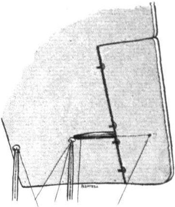
An aileron with its crank lever on the Albatros biplane.

THE CAPTURED ALBATROS FIGHTING BIPLANE. - Plan, front and side elevations to scale.
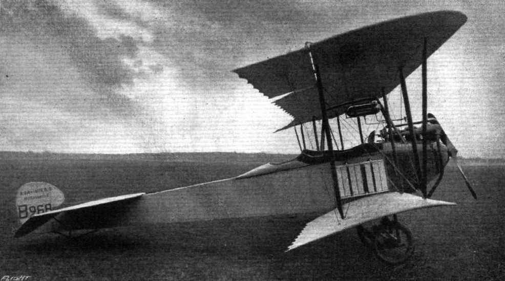
One of the latest Aviatik biplanes, of which a considerable number are in use in the present war.
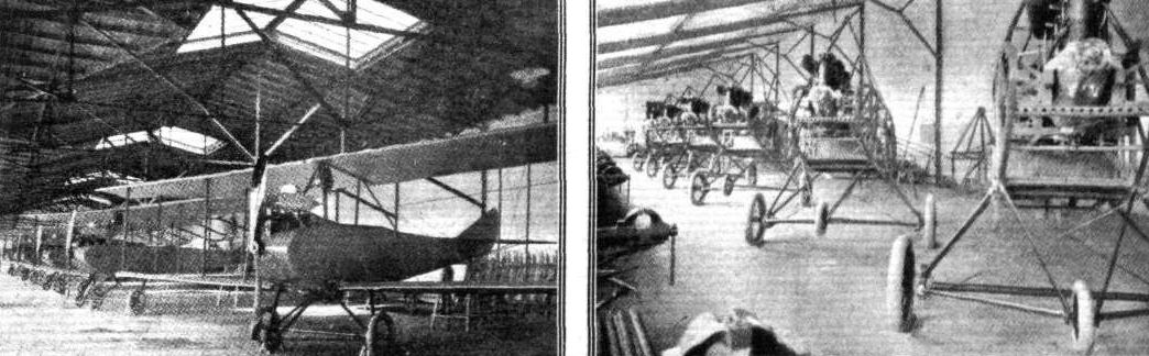
One of the reasons why Germany has available a number of high-powered machines. This photograph of the Euler Works at Frankfort was taken before the war, at a time when German constructors were building Government machines by dozens, and not receiving orders of ones and twos as our own constructors were doing at the time.
Flight, December 10, 1915.
THE CAPTURED GERMAN FOKKER MONOPLANE
ALTHOUGH not being able to lay any claim to being one of the latest types, such as could the Albatros reconnaissance biplane described recently, the captured Fokker monoplane is interesting, if for no other reason, on account of the example it furnishes of what a German aeroplane constructor can, and does do when laying himself out to incorporate his own ideas of construction into a design which is a palpable "crib" of a successful French design. Let it be said at the outset that, considered as a whole, the Fokker monoplane does not appear to us to be an improvement on the French Morane-Saulnier or on its British version as produced by the Grahame-White Aviation Co. It is true that several of the constructional details are very neatly thought out, but these, we think, are more than counterbalanced by shortcomings in other directions.
Aerodynamically the Fokker monoplane differs from the Morane in its proportions and also in the wing section, which is totally dissimilar to that of the French monoplane, having a much flatter "nose" or leading edge and revealing on inspection an entirely different lower camber with its maximum ordinate much farther back from the leading edge.
When turning to the constructional work of the Fokker monoplane radical departures from the French design are noticed. Chief of these is the building up of the body of steel tubes throughout its entire length. In fact with the exception of the wings, which have spars and ribs of wood, the whole machine is constructed of steel tubing. Whether or not this is an advantage is, perhaps, a debatable point, each of the two forms of construction possessing its own merits and disadvantages. By way of example of the last-mentioned, it may be pointed out that a steel tube, while quite strong in its way, may very easily have its strength dangerously impaired by an in itself trivial cause, such as a slight dent made by the dropping of a tool or even by an accidental knock with the toe of a boot.
In the Fokker monoplane longitudinals as well as struts and cross members of the body are, as we have already pointed out, made of steel tubing wrapped with some material that looks like oil cloth, and the function of which probably is to exclude moisture. In shape the body is of rectangular section tapering like that of the Morane to a horizontal knife-edge at the rear. This horizontal stern post takes the form of a short steel tube which serves as a bearing for the main transverse tube of the elevator. This member, which is exactly similar in form to that of the Morane, is also built up of steel tubes and is partly balanced by the portions of it that are in front of the pivoting line. Of similar construction is the rudder, which, as will be seen from the illustrations, consists, roughly speaking, of two semicircles, of which the smaller is in front of the rudder post, thus serving to bring the centre of pressure and the centre of support closer together than they are in an unbalanced rudder.
Carried partly on an extension of the rudder-post and partly on a pyramid formed by four steel tubes is a short skid, sprung in the usual manner by rubber bands, which prevents the tail planes from coming in contact with the ground.
Pilot and passenger are accommodated in a common cockpit, a seat of the kind generally known as the "bucket" type being provided for the pilot, while the passenger apparently has to be satisfied with just a plain board placed immediately behind the pilot's seat. The controls are of the usual type, a central column for the warp and elevator, and a pivoted footbar for the rudder. At the top the lever is terminated by a double handle grip as shown in one of our sketches. On the central portion of this handle is mounted the cut-out switch for the engine in a position where it is within easy reach of either hand.
Owing to the position of the occupants between the main spars of the wings the view in a downward direction is somewhat restricted. In order to improve it the leading and trailing edges have been cut away near the body as shown in the plan view of the machine, and, probably for purposes of facility in firing downwards, windows have been provided in the upper half of the sides of the body. As the aim of the gunner would be made somewhat more difficult by the rush of air that would find its way inwards and upwards through this opening, a small wind screen has been placed at the forward end of it as shown in the illustrations.
In front the body has been enclosed by aluminium sheeting, a cowl of the same material surrounding the upper half of the engine. This cowl, like so many other parts of the design, is very similar to that of the Morane, being provided at its rearward end with two curved shields, which collect the oil thrown out by the engine and prevent it from being blown back along the sides of the body.
The engine, an 80 h.p. version of the Gnome, known in Germany as the Oberursel, is mounted on overhung bearings a la Morane, and drives an Integral propeller of 8 ft. 4 ins. diameter. The Oberursel does not, as far as one is able to judge from outward appearances, seem to be nearly as well made as the original Gnome, although in fairness to its makers one should perhaps give them the benefit of the doubt and admit that this may be due to hard usage and long service. Otherwise it does not differ, again as far as can be seen from an external inspection, from the Gnome motor of the same type and h.p. The tanks are placed as in the Morane, i.e., the petrol service tank and the oil tank being mounted in the front portion of the body, while the reserve petrol tank is placed just behind the cockpit. Placed above the top covering of the body in front of the wind shield is a petrol gauge, or, as the Germans call it, Benzin Uhl (petrol clock), not inaptly since it is provided with hands like a clock and calibrated to indicate the number of litres of petrol in the tank.
One of the greatest departures from Morane practice is, perhaps, to be found in the design of the under-carriage. Whether Mr. Fokker's chassis design is an improvement on that of the French machine is, to our way of thinking, a very great question. If properly carried out the German form of under-carriage might be equal to the well-known Morane, but, as exemplified in the specimen captured, it certainly leaves room for great improvements in the detail construction. The general arrangement will be readily followed by reference to our illustrations. A longitudinal member, formed of a steel tube, is carried on two pairs of "Vee" steel tubes secured to the lower longitudinals of the body. Hinged to this tube near the point of attachment to the front "Vee" are the two stub axles, which slope downwards towards the wheels. Two other tubes slope upwards to the sides of the body, where they are linked to short transverse horizontal levers pivoted centrally in the floor of the body. Shock absorbers wound round these levers and a transverse strut in the body provide the springing. A diagrammatic sketch of the arrangement will, supplemented by sketches of the details, explain the action. From the axles radius rods in the form of steel tubes run to the apex of the rear "Vee," the hinge forming the fulcrum for the radius rods as well as those for the stub axles being of a decidedly flimsy character. Again, the attachment of the lift cables to the forward end of the longitudinal member of the chassis looks somewhat amateurish, the cables simply being spliced with an eye sufficiently large to slip over the end of the tube, where it is secured by a washer, which again is held in position by a split pin. Although looking rather unfinished, this form of attachment probably is quite adequate, but it cannot compare in neatness with the Morane method of securing the lift cables.
One very neat fitting we noticed in the bracing system of the wings, i.e., the quick release by means of which the bracing cables are attached to the wing spars. It consists, as will be seen from the accompanying sketch, of a hemispherical hollow socket having cut in its side a T-shaped slot and secured, how we were unable to ascertain, to the sheet steel clip gripping one half of the spar. In the top of the T the flat head of the turn buckle has just room to pass, all that is necessary to detach the cable from the spar being to slacken the cable by giving the turnbuckle a few twists and the head may be pulled out of the cross slot of the T. In a similar way the cable is quickly attached by reversing the process.
In plan form the wings of the Fokker are similar to those of the Morane, having their ends considerably raked so as to increase the effectiveness of the warp. The main spars, which are of I section wood, are fitted at the root with a socket terminating in an eye through which a short bolt passes, thereby securing the spar to the corresponding lug on the side of the body of the machine. On each side of the body and a short distance in front of the chassis struts is a bracket having at its outer end an eye of the same size as that of the spar lug. When it is desired to transport the Fokker by road the wings are detached in the manner described above, and the front spar is placed with its root on this bracket, the same bolt that is used for securing the spar in the flying position being employed to secure it to the bracket for transport. A steel hook bolted to the front spar near its outer end fits into a socket a few inches in front of the tail skid attachment, and when a couple of straps have been taken around the wings the machine is ready for transport.
The top wing cables are attached to a two-legged cabane of steel tubes as in the Morane. From the apex of this cabane two cables are taken to the top of the engine bearer, thus staying it in a forward direction. Being placed in line with the front wing spars the top warp cables, which pass over pulleys, naturally slope backwards to the rear spar, thereby providing the rearward staying of the cabane. The lower warp cables run from the wings to short crank levers on the apex of the rear "Vee" of the undercarriage, these levers being operated through vertical cables by a transverse crank lever on the longitudinal rocking shaft inside the body. The warp cables, it will be noticed, are not in line with the front cables, the reason being that the rear spar is longer than the front, and requires different spacing of cable attachments to preserve the load distribution.

"FETCHED DOWN." A Fokker monoplane, of which the Germans employed a considerable number during the earlier part of the war. These machines are now mostly used for school work.
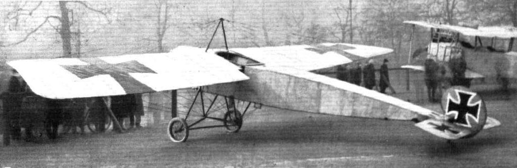
Three-quarter rear view of the captured Fokker monoplane.

Three-quarter front view of the Fokker monoplane.
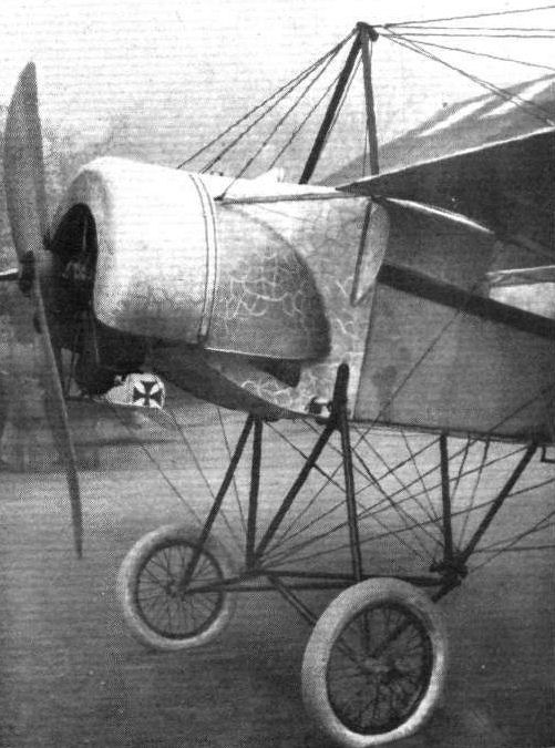
Undercarriage and engine housing of the Fokker monoplane.
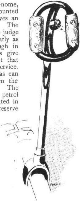
The control lever of the Fokker monoplane.
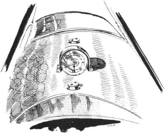
The petrol "clock" on the Fokker monoplane.

Detail of shock-absorbing arrangement and step bracket on the Fokker monoplane.
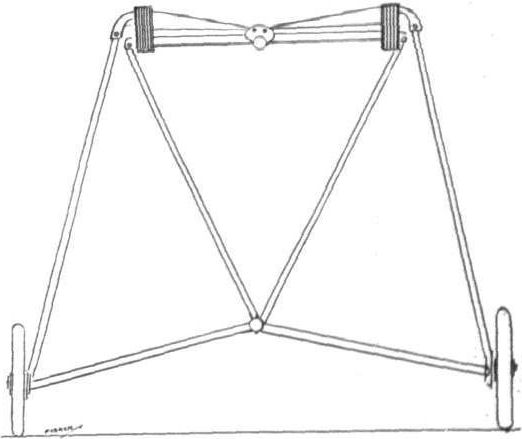
Diagrammatic sketch of chassis.
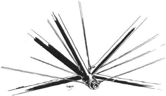
Attachment of lift cables to chassis on the Fokker monoplane.
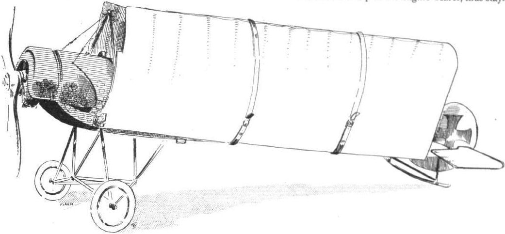
The Fokker monoplane with wings folded for transport.

Attachment of lift cables to main spars on the Fokker monoplane.
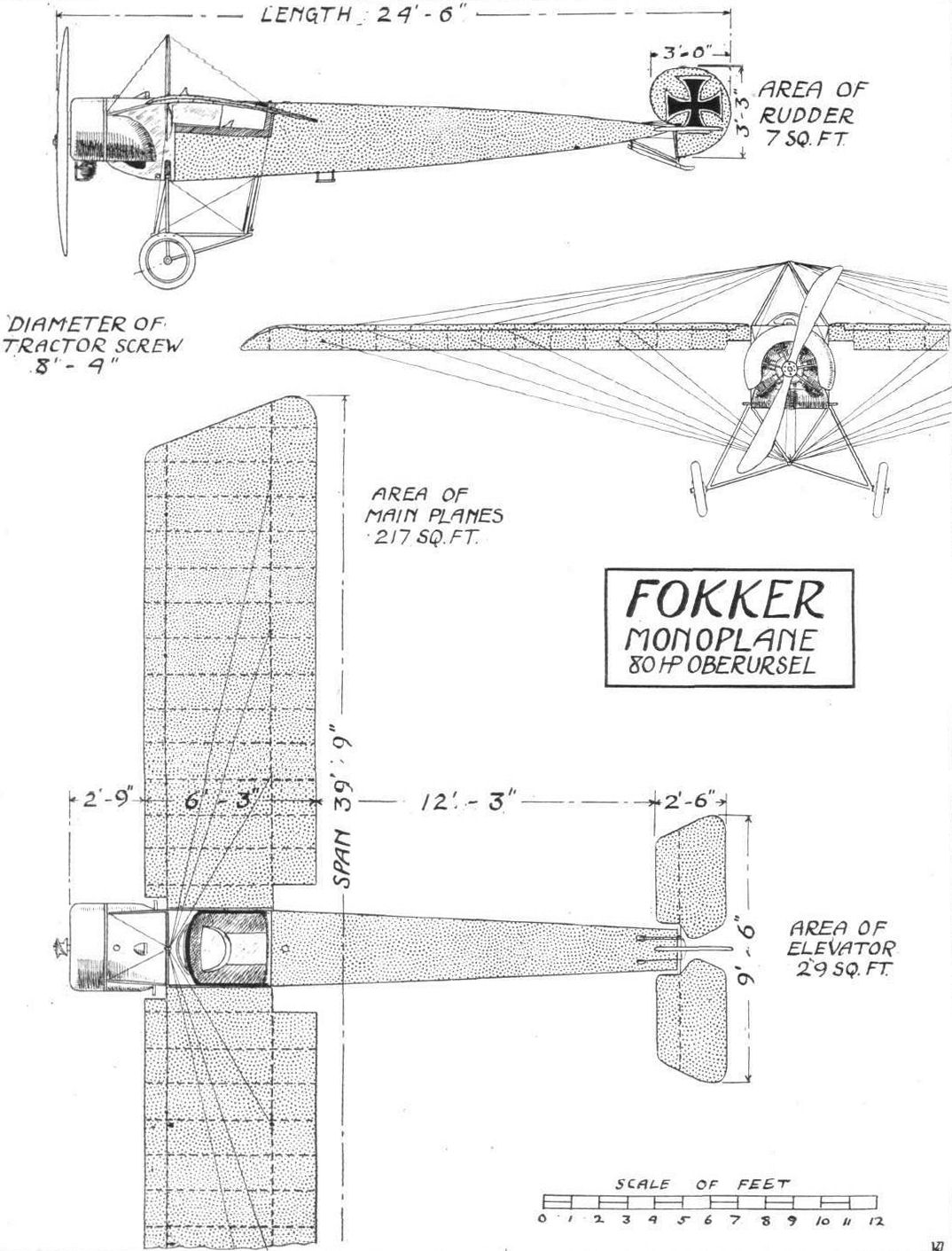
THE FOKKER MONOPLANE. - Plan, front and side elevations to scale.
Flight, April 2, 1915.
ANOTHER GERMAN SEAPLANE.
THE B.F.W. (BRANDENBURGISCHEN FLUGZEUGWERKE).
SINCE giving a description of some of the seaplanes entered for the Warnemunde-Scandinavia Seaplane Race, which was postponed on account of the war, the following particulars are to hand of another machine designed specially for this contest - the B.F.W. seaplane. In its general lay-out, this machine follows the lines of other German biplanes of the tractor type, with which our readers are already familiar, having a rectangular section body, tapering almost to a point in the nose, where is housed the 150 h.p. Benz motor. The fuselage, however, is of somewhat unusual construction in that not only is it covered with three-ply wood, but it is strengthened internally with the usual diagonal cross-bracing. In the Albatros, it will be remembered, no internal cross-bracing of any sort is employed, the necessary stiffness being provided by the three-ply covering. In the B.F.W. seaplane the internal cross-bracing of the body has been employed to better prevent the fuselage from warping under the action of sea water. The resemblance to the Albatros biplanes will be easily understood when it is pointed out that this machine was built by Ingenieur Heinkel, who was formerly chief engineer to the Albatros firm. In the front portion the body is covered with a turtle-back of three-ply wood, finishing off behind the pilot's seat in a tapering shape somewhat similar to that found on the Deperdussin racing monoplanes, and evidently intended to form a streamline continuation of the pilot's head. Immediately behind the engine is placed the observer's seal, and between him and the pilot are mounted the fuel tanks. The radiators, which are of the usual type, are mounted one on each side of the body.
Carried on a structure of steel tubes are the two main floats, which are of large size and placed fairly close together. In front the floats are of the V-bottom type, flattening out gradually towards the step, which occurs approximately under the centre of gravity of the machine. Immediately behind the step the float bottom is perfectly flat, gradually running into a slight V-bottom at the stern.
The main planes, which are of large span, are of the usual plan form, that is to say, rectangular with rounded corners. They are connected by three pairs of spruce struts on each side of the fuselage, and the upper main plane is attached, in the centre, to a steel tube cabane resting on the upper longitudinals of the body. The attachment of the struts to the spars is very reminiscent of that employed in the Albatros biplanes, and consists of a bell-shaped piece of steel, secured by means of a bolt passing down through the spar, as shown in the accompanying illustration. The bracing cables are attached to this bell-shaped steel piece by passing the lower end of the wire strainer, which is fitted with an anchor-piece as shown in the sketch, through openings in the sides of the bell. This fitting does not impress us as being such a good piece of work as that of the Albatros machines, in which, if we remember rightly, the strainers were attached to a ring resting inside the steel bell.
Another of our sketches shows the trolley used for transporting the machine short distances overland. The two wooden cross-members, it will be seen, are partly channelled out to receive the two transverse steel tubes of the chassis, and for starting off from a shallow beach all that is necessary is to run the machine out until sufficiently deep water has been reached, when the trolley will automatically be left behind, and the machine free to proceed on its floats.
The subject of another of our sketches is the tail float and planes. The stabilising plane is semi circular, and to it are hinged the two elevator flaps. The rudder, which is partly balanced, is covered at the lower end with a copper skin to protect it against the action of sea water, and is used for steering on the water at low speeds. A small tail float of the form shown in the sketch takes the weight of the tail planes.
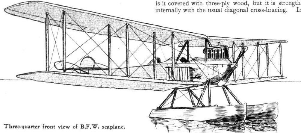
Three-quarter front view of B.F.W. seaplane.

Three-quarter rear view of B.F.W. seaplane.
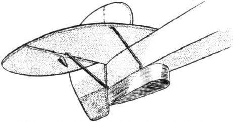
Tail planes and float of B.F.W. seaplane.
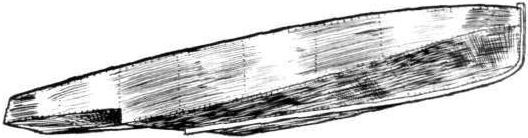
View from below of one of the main floats of the B.F.W. seaplane.
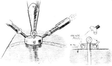
Sketch showing cable attachment to inter-plane struts.

The trolley used for transporting the B.F.W. seaplane from its hangar down to the beach.
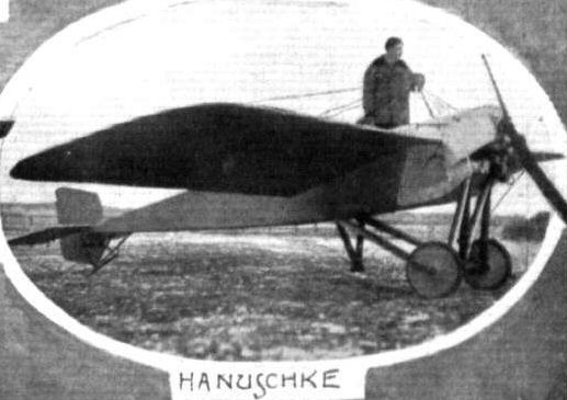
SOME NEW GERMAN MILITARY MACHINES. - A very marked tendency towards the standardisation of the Albatros and L.V.G, type of biplane will be noticed. An exception is the Fokker biplane with a rotary engine, evidently designed for scouting purposes. The Hanuschke monoplane, to put it mildly, haa a strong family resemblance to the Morane-Saulnier.
SOME NEW GERMAN MILITARY MACHINES. - A very marked tendency towards the standardisation of the Albatros and L.V.G, type of biplane will be noticed. An exception is the Fokker biplane with a rotary engine, evidently designed for scouting purposes. The Hanuschke monoplane, to put it mildly, haa a strong family resemblance to the Morane-Saulnier.

Captor and Captive. - A German L.V.G. biplane forced to descend by the French aviator, Adjudant N., who was flying the little fast single-seater Morane-Saulnier monoplane seen in the photograph beyond the German machine.
Flight, April 9, 1915.
A NEW OTTO BIPLANE.
GENERALLY speaking, the Munich firm of Otto had confined their attention, before the war, to the production of machines of the engine-behind type. As, however, the German military authorities, unlike our own, discouraged the construction of "pusher" biplanes, nearly all the firms who had up to then been turning out engine-behind machines, concentrated on the production of tractors. A new one of these built by the Otto firm was completed and tested shortly before hostilities broke out, and as it showed excellent capabilities both in weight-lifting, speed and carrying capacity, it would appear probable that a number of these machines are being used against us, and a few notes regarding the type should therefore be of interest.
Fundamentally, the new German Otto biplane follows fairly closely on standard lines, and such improvements as have been effected are mostly to be found in a reduction of head resistance wherever possible, a reduction which has resulted in a considerably higher speed than that usually found in German aeroplanes. The body, which is of rectangular section, is topped with a turtle back in which are the openings for the pilot's and passenger's cockpits and for the engine. The rounded nose, which is covered with aluminium sheeting, provides a very good entry for the air, thus contributing considerably towards the high speed obtained, i.e. about 87 miles per hour. The engine - a 150 h.p. Rapp - is mounted on stout ash bearers in the nose of the body, and is, as will be seen from the accompanying illustration, fitted with a long exhaust pipe running back along the side of the fuselage to a point behind the pilot's seat, so as to convey the exhaust gases out of the way of the occupants.
In the floor of the body, ahead of the front seat, which is occupied by the observer, an opening is provided through which an unrestricted view is obtained in a downward direction for purposes of observation or for taking photographs. In addition, mica windows are fitted on each side of the body in front of the observer's seat, so that by stooping down inside the body he can be out of the draught and still obtain a fairly good view on each side.
In plan form the main planes, of which the upper one has a slight overhang, have a pronounced taper towards the tips, that is to say, the greatest chord is in the centre, the leading edge sloping backwards and the trailing edge sloping forwards. The lower planes are attached to the sides of the body, whilst the upper planes are attached to a centre section carried on a steel tube structure coming up from the upper longitudinals of the body. Small service tanks for petrol and oil are fitted in the angle between these centre struts and the centre section of the upper plane. Two pairs of steel struts on each side of the body connect the upper and lower main planes, and cross-bracing is effected by means of stout stranded cables. The drift is taken by internal cross-bracing of the wings and by cables running from the top of the first front inter-plane strut to the nose of the body. Control is by means of the usual hand lever for longitudinal and lateral control, and a pivoted foot-bar for directional control. Large sized ailerons are fitted to the trailing edge of the upper plane only.
A chassis of the simple V type, usually found on modern German tractors, is fitted. It is built up of stream-lined steel tubes, cross braced with thick stranded steel cables, and carrying the tubular axle which runs right across from side to side. The tail planes consist of a semicircular stabilising plane, to which is hinged the divided elevator, and of a partly balanced rudder, hinged to the stern-post of the body. Sufficient fuel is carried for a flight of five hours' duration, which gives a radius of action of approximately 220 miles. No figures are available regarding the rate of climbing, but it is said to be exceptionally good.

Flight, November 12, 1915.
THE OTTO BIPLANES.
OF the German aeroplane constructors who have paid special attention to the development of the all-steel machine few have met with greater success than have the Otto works at Munich. In the accompanying illustrations are shown two types of fuselages which are similar as regards construction, but differ in that one is designed for a stationary engine, whilst the other is of a slightly different form in front to take a rotary motor. One feature common to all Otto machines is the employment throughout of seamless chrome nickel steel tubes for longerons and struts of the fuselage. The attachment of the struts to the longerons is by means of special steel clips, which grip the various members without piercing them, a form of construction which has the further advantage that it facilitates replacement in case of fracture.
Attachment of the wings to the fuselage is by means of similar steel clips so designed that it is possible to slide the wings a short distance along the longerons so that a heavier or lighter engine may be fitted and the balance of the machine preserved by shifting the wings slightly backwards and forwards. In addition to this adjustment the angle of incidence can be altered to suit various purposes. In the machines shown both these adjustments are carried out when erecting the machine, but, according to information available, later types will be fitted with the necessary levers for carrying out this operation while in the air, an improvement that has no doubt been rendered effective by this time.
Wing spars as well as interplane struts are, like the fuselage, made of steel tubes, the struts, needless to say, being of streamline section, and bracing is effected by means of stranded steel cables. The engine, in the case of the stationary motor, is mounted on stout ash bearers supported from the longerons of the fuselage; while in the machine designed for a rotary engine the bearers are more or less of a similar type to that employed on British machines.
Although being made of steel throughout, the Otto biplane is said to be lighter than one of the same size made of wood, and the factor of safety in the wings is stated by the makers to be 8.
A chassis of the usual simple type found in the majority of German military machines is fitted, the material used being streamline steel tubes for the struts and a tubular axle slung by rubber bands. Quickly detachable steel clips secure the chassis struts to the lower longerons of the fuselage, and the chassis can, like the wings, be moved slightly backwards and forwards to obtain perfect balance on the ground for engines of different weight.
The older machines were fitted with 100 h.p. Mercedes engines, but in view of the exceptional facilities for changing over, it appears highly probable that the latest ones have engines of 150 h.p. or more, which, in conjunction with the variable angle of incidence, should give a machine of more than ordinary utility.
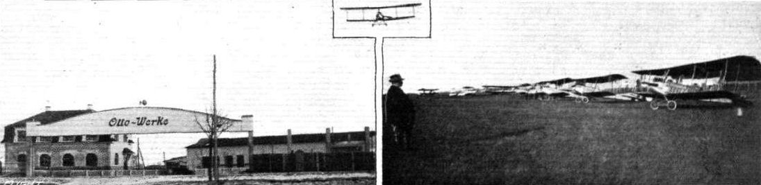
THE OTTO AIRCRAFT WORKS AT MUNICH. - On left the works, and on right a row of Otto biplanes ready for delivery. The person in the foreground is alleged to be the chief pilot and tester, and has possibly been so placed as suggestive of the lifting power of the Otto machines.

TWO VIEWS OF THE OTTO ALL-STEEL FUSELAGES. - On the right, the nose of the body and chassis of the machine fitted with a stationary engine, and on the left the nose of the biplane with a rotary motor.
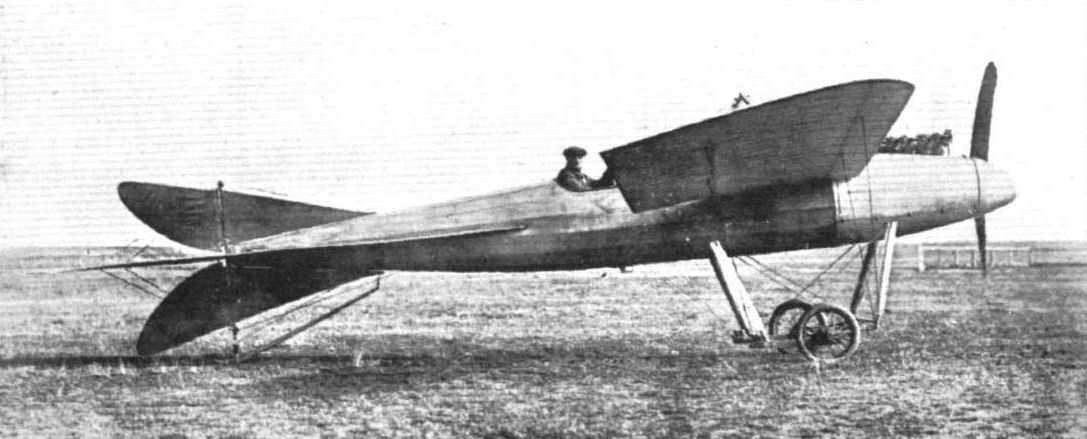
A GERMAN "TORPEDO" MONOPLANE. - In spite of the fact that the German authorities have practically abandoned the monoplane type for active service, it appears that German designers are still experimenting with Eindeckers. The machine shown in the above photograph has evidently been designed for speed, judging from its excellent streamline body. The way in which the engine has been all but hidden away Inside the covering is, of course, the result of an attempt to reduce head resistance to a minimum, as is also the nose piece fitted over the boss of the propeller. Strangely enough, the undercarriage is not of the simple "Vee" type that is so much favoured by German designers. Note the symmetrical rudders and tall plane.
Flight, July 2, 1915.
EDDIES.
There has been quite a lot of talk lately in certain quarters about a German firm building a copy of the Bristol scout, the machine in question being the Rex biplane. From the accompanying illustration it will be seen that there is very little resemblance between the Rex and the Bristol. About the only similarity is the staggering of the planes and the fact that only one pair of struts on each side of the fuselage separates the main planes. The fuselage is entirely different, being if anything more reminiscent of the Morane than of the Bristol scout. The inner pairs of inter-plane struts are placed outside the body, and the elevator is of the balanced type, whilst no tail plane is fitted. If the Rex firm have been building this machine under the impression that they were making a copy of the Bristol scout, they are likely to meet with a few disagreeable surprises as regards performances, for the five-cylinder R.A.W. engine with which it is fitted looks capable of about 40 h.p. at the most.
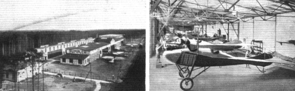
On the left a view from above of the Rumpler aeropiane works at Johannisthal, Berlin, and on the right a view of the erecting shop.
Flight, July 9, 1915.
THE RUMPLER-TAUBE MONOPLANE.
ALTHOUGH at the present time the Germans are not using the Taube type of monoplane so much as at the commencement of hostilities, they have not entirely abandoned them, and in fact efforts are being made to bring them more into line with other types of monoplane as regards speed. This is especially noticeable in the case of the Rumpler-Taube, which is described in the following notes.
Viewed from this standpoint, the prominent features of the Rumpler-Taube will be seen to consist in the absence of the girder understructure bracing the wings - a distinctive characteristic of nearly all Taubes - the hinged balancing flaps, and the orthodox type of tail planes in place of the original flexing plane. Though somewhat modified, the main planes still have the Zanonia form, and in addition they are very slightly swept back. The angle of incidence decreases towards the tips, where the balancing flaps present a slight negative angle of incidence. An interesting point in connection with these balancing flaps, which have an area of 15 sq. ft. each, is that they are hinged along an axis forming an angle with the transverse axis of the main planes. They also operate in an upward direction only, so that a downward reaction is presented on the side of the higher wing. Cable bracing is employed top and bottom, the cables in each case being anchored to pyramids of tubular steel struts mounted above and below the body respectively; the underbracing is thus quite independent of the undercarriage, and should the latter become strained the adjustment of the planes is not disturbed. Ash and American white pine are employed in the construction of the main planes, which are built up on two main spars situated fairly close together. Portions of the planes adjacent to the pilot's cockpit are cut away in order to provide a view below. The tail consists of a triangular stabilizing surface, in two portions mounted one on either side of the body, and two elevator flaps hinged similarly to the balancing flaps, i.e., at an angle. The vertical rudder is mounted between the elevators with a triangular vertical fin in front.
The body is rectangular in section, tapering to a vertical knife-edge at the rear. Ash is the material employed in its construction, and the portion forward of the cockpits is covered with sheet metal, and that aft with fabric. The engine, a 100 h,p. 6-cylinder water cooled Mercedes, is mounted in the nose, with the Windhoff radiator directly above it. This radiator is made up of aluminium tubes, and being mounted immediately above the engine, the water in the jackets is always under pressure, thus preventing air locks or vapour pockets. The engine drives direct a Reschke tractor screw 8 ft. 6 ins. diameter and 4 ft. 9 ins. pitch. Immediately behind the engine are the fuel tanks, and then come the pilot's and passenger's cockpits, the pilot being seated behind the passenger. The control consists of a vertical wheel mounted on a rocking column, the former operating the balancing flaps and the latter the elevator, whilst the rudder is actuated by pedals. A simple but strong under carriage is fitted consisting of two pairs of steel V struts of streamline section, with a tubular axle carrying a pair of disc wheels, attached, by means of rubber bands, to the apex of each V. A short skid attached to the body at the rear protects the tail.
The following are the main characteristics of the Rumpler-Taube :- Span, 46 ft.; maximum chord, 9 ft. 6 ins.; overall length, 27 ft.; supporting area, 300 sq. ft.; weight fully loaded, 1,840 lbs.; speed, 74 m.p.h.; climbing speed, 2,600 ft. in 6 mins. (full load, 4 hours fuel and 400 lbs. useful load).

Three-quarter view, from the front, of the Rumpler-Taube monoplane.
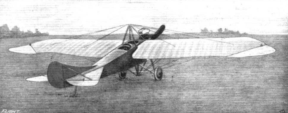
Three-quarter view, from behind, of the Rumpler-Taube monoplane.
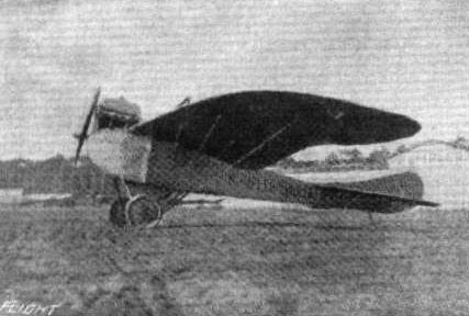
Side view of the Rumpler-Taube.

THE RUMPLER-TAUBE MONOPLANE. - Plan, side and Front elevations to scale.
Flight, June 18, 1915.
AN ITALIAN MONOPLANE THE GABARDINI.
OF the several Italian-designed aeroplanes, the Gabardini monoplane, built at Cameri, is perhaps the most interesting and one of the most successful. It was the Gabardini monoplane that was employed for the first civilian aviation school at Cameri, whilst this make of machine has several non-stop flights to its credit, including Milan-Rome, Milan-Turin and Milan-Venice (with three passengers).
The Gabardini monoplane - described in FLIGHT on November 6th last - although resembling somewhat the Nieuport, really differs from this French make considerably. For instance, it is built mostly of steel, whilst the body is peculiar in that from the nose to a point immediately behind the pilot's cockpit it is rectangular in section, after which it is of triangular section. The steel tubes forming the body are reinforced with wood, providing a light but extremely strong combination.
The wings, which have an upturned entering edge, like the Nieuport, are built up on tubular steel spars with wood I-section ribs loosely mounted thereon so that there is a certain amount of free movement for warping. Another interesting feature is the tail planes, consisting of a semi-circular stabilising surface and two similarly shaped elevator flaps, which are mounted on the body some distance from the rudder, so that the latter has a wide range of action. The engine employed is an 80 h.p. Gnome, built in Italy by the Fabbrica Italiana Motori Gnome at Turin.
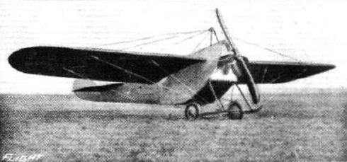
A Gabardini monoplane with 80 h.p. Italian-built Gnome engine.
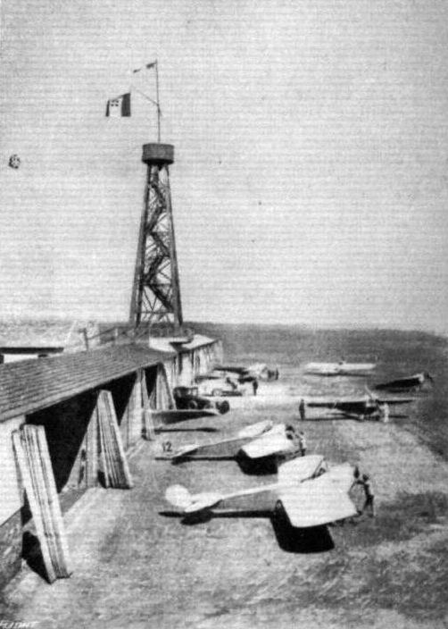
The sheds and machines at the Gabardini aerodrome at Cameri (Novara).
Flight, April 16, 1915.
THE BEACHEY EXHIBITION MONOPLANE.
LINCOLN BEACHEY, America's most daring "stunt" flyer, who met his death just recently whilst giving a looping exhibition at San Francisco, had only shortly before got out the designs for a neat little monoplane which he intended to use in his future exhibitions, and two of these machines were being built at San Francisco. Most of the details of design were worked out by Mr. W. S. Eaton, special attention having been given to the quick assembling and dismantling of the machine. By the use of specially designed fittings both operations should be accomplished within 30 minutes.
The wings, of the rigid non-warping type, having a Morane-Saulnier plan form, are in two 12-ft. sections and perfectly straight; that is, they have no dihedral angle. The wing section employed has been calculated from N.P.L. data to give speed; the maximum and minimum camber are 5 1/4 ins. and 1 in. respectively, and the under portion of the leading edge is slightly turned up as in the Nieuport wing section. Spruce is employed for the main spars, which are of I section tapering towards the outer extremities. The front spar is located 7 1/2 ins. from the leading edge, which is of wood, and the rear spar is 1 ft. 6 1/2 ins. from the trailing edge, which consists of steel tubing, except for a wood portion where the balancing flaps are hinged. The main ribs, spaced 16 ins. apart, are built up as shown in one of the accompanying sketches, of spruce flanges and cut-out fillers bored for lightness. Between each main rib are wood battens running from leading to trailing edge, whilst from the front spar to the leading edge a false rib is placed between the main ribs and the battens, which thereby greatly strengthens the front portion of the wing. The wings are internally braced with steel cable, and covered with Irish linen doped with Christofferson varnish. The attachment to the body is by means of quick detachable clamps, whilst the external bracing is by extra heavy steel cable, the top cables being attached to a pyramid of four steel streamlined struts mounted on the body above the pilot's cockpit, and the under cables are attached to the landing carriage.
Hinged to the outer extremities of the rear spars are two balancing flaps, each measuring 4 ft. on the hinging edge, 3 ft. 6 ins. on the trailing edge, by 2 ft. 3 ins. chord. They are constructed of tubular steel and spruce, the former for the outer frame and the latter for the attaching edge and ribs. These flaps are inter connected, and are operated by a Curtiss type shoulder yoke, the control wires being carried in tubing placed within the wing along the rear spar. The tail planes consist of a horizontal stabilising surface in two portions, each measuring 3 ft. 6 ins. by 2 ft. 6 ins., one mounted either side of the body, and two elevator flaps (exactly similar in shape and size to the balancing flaps) hinged to the trailing edge of the stabiliser, and a partly balanced vertical rudder in between the elevators. The latter are operated by a to-and-fro motion of a vertical column, upon which is mounted a wheel actuating the rudder. The section of the stabiliser is similar to that of the wing, only, of course, reduced in proportion.
The body, which is 12 ft. 9 ins. in length, is divided into two portions fore and aft. The front portion, containing the pilot, engine, wings, undercarriage, &c, measures 5 ft. 9 ins., with a maximum depth and width of 2 ft. 3 ins. The rear portion, measuring 8 ft., tapers to a horizontal knife edge at the rear, where it also narrows somewhat. Both sections are built up on more or less usual lines with four longitudinals tapering towards the rear and streamlined connecting struts, all cable braced. These two sections are connected by very strong quick detachable joints. The nose of the body has an aluminium covering which forms a cowl over the engine - an 80 h.p. Monosoupape-Gnome - and a turtle back, in which is the pilot's cockpit, along the forward section of the body. The reason for streamlining the body struts is that should it be found necessary the covering on the after portion of the body can be removed, leaving the latter open as on the Bleriot. The engine is supported in a specially constructed steel bearer, mounted on the nose of the body. A 7 ft. 9 in. tractor screw, with 7 ft. 4 in. pitch, is direct coupled to the engine, and the fuel tanks are placed under the engine cowl. In front of the cockpit, which is well padded, is a small transparent wind shield that greatly reduces the wind pressure on the pilot's face. Of the three-wheeled type, the undercarriage is exceedingly strong; no shock-absorbing devices are employed, the necessary resiliency being provided by the 20 in. by 4 in. tyres fitted to the wheels. The latter are arranged two 5 ft. apart under the pilot's cockpit, and one 3 ft. 10 ins. in advance of the others. All three are connected by a triangular frame of steel tubing, whilst two pairs of steel streamlined struts connect the latter with the body, the whole carriage being cable-braced.
The general dimensions of the Beachey monoplane are: Overall span, 27 ft. 6 ins.; span of wings, 26 ft. 6 ins.; chord, 5 ft.; supporting area, 110 sq. ft.; overall length, 18 ft.; weight empty, 520 lbs.; speed, 45-100 m.p.h.; gliding angle, about 1 in 5.
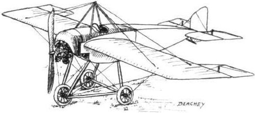
THE BEACHEY MONOPLANE. - Three-quarter view from the front.

THE BEACHEY MONOPLANE. - A main rib, showing the wing section and construction.

The Beachey Monoplane. - Section of one of the steel struts.
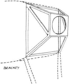
The Beachey Monoplane. - The steel engine mounting.
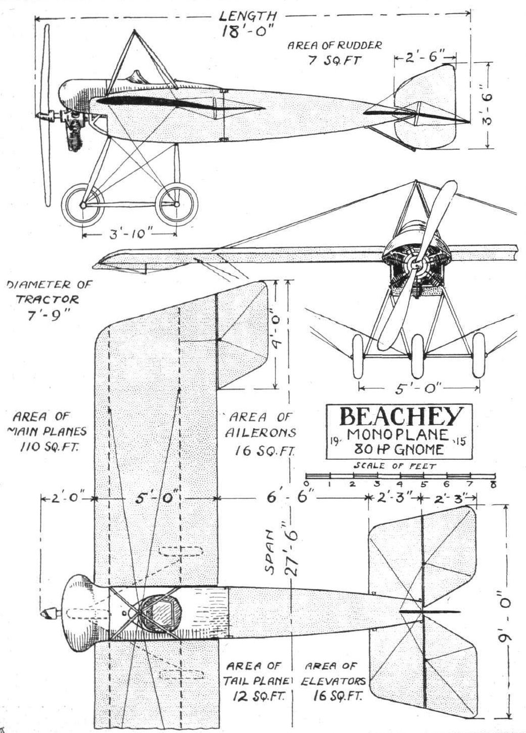
THE BEACHEY MONOPLANE. - Plan, side, and front elevation to scale.
Flight, August 20, 1915.
THE 1915 BENOIST FLYING BOATS.
THE flying boats manufactured by the Benoist Aeroplane Co. of Chicago, Ill., are among the few - at one time the only - craft of this type in which the motor is mounted in the hull. A low centre of gravity is thus obtained, and the craft is thereby made as seaworthy as is possible, and good stability in the water is as essential as good stability in the air. It is generally accepted, however, that a low centre of gravity in an aeroplane is not always a desirable factor where stability in the air is concerned, so it will be seen that it is a somewhat difficult proposition to so design the craft that the advantage of one condition is not to be outweighed by the disadvantage of the other. That the designer of the Benoist flying boat succeeded in surmounting this difficulty is borne out by the fact that the first machines to be built at once made a name for themselves on the score of good stability, both in the water and in the air. Many notable performances are to their credit, especially the first regular daily passenger air service between St. Petersburg and Tampa, Fla., a distance of about 20 miles across Old Tampa Bay, which was started on January 1st last year.
The 1915 Benoist machines differ from the previous models only in a few details, the most important of which is the location of the engine. This is still placed in the hull, but instead of being mounted on the bottom, as before, it is now half way up in the hull, so that it is almost level with the lower plane. Here is, therefore, a compromise between the engine-in-the-hull type and the engine-between-planes type, and the arrangement appears to have given very good results. Another modification is to be found in the boat, which now has a roomier cockpit, and in place of the canvas hood over the latter there is an inverted V-shaped deck. The boat is of the single step type, very wide and deep forward, tapering to a point at the stern. The bottom is perfectly flat laterally throughout, and curves up from the step to the bow. Aft of the planes the boat has an inverted V deck, which has the advantage of allowing the water to flow off easily in the event of the waves breaking over the hull. This, and the ample freeboard forward, renders the boat exceptionally seaworthy. The step is 5 ins. deep, and is situated some distance behind the centre of pressure, 10 ft. 6 ins. from the bow. From the nose to the step the hull is built up of two layers of 1/4 in. spruce planks, having a layer of canvas set in between, whilst aft of the step it is constructed of single 3/8 in. spruce planks, which are reinforced inside at the seams with spruce battens. Spruce planking 3/8 in. thick, laid in the same manner, forms the sides, and the upper portions are covered with mahogany. The framework consists of spruce longitudinals and ribs, and the boat is divided into five watertight compartments. Six coats of Valspar outside and three coats inside are put on the hull, which has a total length of 24 ft. 6 ins., and he maximum beam is 3 ft. Pilot and passenger are seated side by side immediately in front of the main planes, and he engine is mounted on strong bearers between the main spars of the lower plane. Of 8 ft. 6 ins. in diameter, the propeller, mounted high up behind the main planes, is driven at engine speed by means of a roller chain-running in a tubular guard, while the pull of the chain is taken by a hollow radius rod. Mounted some two feet below the top plane the hollow steel propeller shaft extends forward as far as the cockpit, where provision is made for the engagement of a crank for starting the engine. A pair of spruce struts take thrust reaction, and at the same time contribute towards the support of the rear propeller shaft mounting.
Top and bottom planes are of equal span, 36 ft., and have a chord of 5 ft. and a gap of 6 ft. They are also each in two sections, being divided midway where they are attached to the boat in the case of the lower plane, and to the innermost interplane struts in the case of the top sections. The aforementioned interplane struts, of which there are two pairs, are arranged A fashion, and it is to the apex of the A the top plane sections are attached.
This arrangement is not only simple but forms a strong support for both planes and propeller mounting. There are three pairs of vertical struts on either side of the boat separating top and bottom planes. The planes themselves are constructed on more or less orthodox lines, the foremost of the two main spars for each plane forming the leading edge, the other being situated one foot from the trailing edge. Hinged to each outer extremity of the rear spars of both top and bottom planes is an aileron measuring 7 ft. by 1 ft, all four being interconnected, so that when the pair on one side moves up the pair on the other moves down. Under each extremity of the lower plane is mounted a float for supporting the wing tips on the water when the machine is taxying. The tail consists of a small stabilising surface of high aspect ratio, to the trailing edge of which are hinged two large elevator flaps with a partly balanced rudder in between. The lower portion of the latter is of wood and projects into the water, and thus acts as a water rudder when taxying. The whole tail is supported about two feet above the boat by a stout ash strut extending from the stern and by a series of bracing tubes. The control is either of the Benoist or Deperdussin type, the former consisting of two levers, the right-hand one operating the ailerons and elevators, and the left-hand one the rudder.
If required, arrangements can be made for mounting the engine up between the planes, the main characteristics remaining as before.
The specifications of Model "A," 75 h.p. two-seater, are :- Span, 36 ft.; chord, 5 ft.; gap, 6 ft.; supporting area, 360 sq. ft.; overall length, 28 ft.; weight, empty, 1,180 lbs.; useful load, 650 lbs. Another model, "B," a 100 h.p. for two or more passengers, is also manufactured. This machine is practically the same as model "A," with the following principal modifications :- Span, 51 ft. 6 ins.; supporting area, 497 sq. ft.; weight, empty, 1,390 lbs.; useful load, 800 lbs. The chord and gap are the same as in Model "A," and the engine can also be mounted between the planes if desired, in which case another seat is provided behind that of the pilot, where the engine would be if located in the hull. The latter is similar to that of the other model, and has a beam of 3 ft. 6 ins., and a length of 24 ft.

Three-quarter front view of the 75 h.p. Benoist flying boat.

Three-quarter rear view of the 1915 75 h.p. Benoist flying boat.
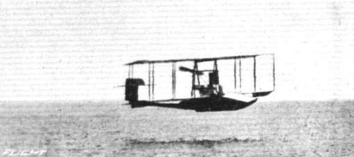
The 1915 75 h. p. Benoist flying boat in flight.

THE 1915 75 H.P. BENOIST FLYING BOAT. - Plan, side and front elevations to scale.
Flight, September 24, 1915.
WATERPLANE SPORT IN AMERICA.
MR. ASTOR'S BURGESS-DUNNE SEAPLANE AND ITS FLOATING HANGAR.
SEAPLANING as a sport is rapidly increasing in vogue among our American cousins, thanks chiefly to wealthy enthusiasts such as, to mention a few, Verplank, McCormick, and Astor. While the two former have selected the Curtiss flying-boat type as best suited to their purpose, Mr. Vincent Astor, the American millionaire, has decided on a single float seaplane of the Burgess-Dunne type. Being a member of the New York Yacht Club it is only natural that Mr. Astor should during the past summer have had his machine stationed at Marblehead, where it has got through a great deal of air work over the bay. As built by the well-known Burgess firm of Marblehead, Mass., the Burgess-Dunne seaplane has proved very successful in every way both as regards weight-lifting and speed. Its stability is said to be perfect in all sorts of weather, and it appears to leave the surface easily and without any fuss when getting away. A single-stepped central float takes the greater portion of the weight, assisted, when the machine is at rest, by the two wing tip floats. As soon as the speed reaches a certain point, however, these wing tip floats leave the water, and the machine is then supported on the central float only. With a Curtiss OXX engine the Burgess-Dunne does over 65 m.p.h., and the total weight lifted is over 2,000 lbs.
In order to increase the usefulness of his machine, Mr. Astor has had a special floating hangar built for it by the Burgess Company. Should its owner so wish, the hangar and machine may be towed from Marblehead Bay to any other stretch of water, such as, for instance, the Hudson River, and used there for inland service. The floating hangar itself is highly interesting, as it is of a somewhat unusual design. It consists, as will be seen from the illustrations, of a large punt-shaped float on which rests the hangar itself, leaving a narrow promenade running round all four sides. From the stern of the hangar projects a well-supported steel beam, which carries on two small trolleys a differential hoist. The machine is brought up to the hangar after a flight, and the hoist cable is hooked into a ring just in front of the engine. Two men can now lift the machine out of the water, and when this has been accomplished the plane is swung round until it faces across the hangar, when a slight pull on the trolley suffices to bring it under cover, securely sheltered from rain and wind. There can be little doubt that the combination of the Burgess-Dunne seaplane and the floating hangar in which it is housed is admirably adapted for popularizing seaplaning, as it does not confine the activity of the machine to one particular locality, but enables moves to be made to suit the desires of the owner. If he so wishes, the summer months may be spent in the North, either on the Atlantic Coast or on one of the many inland lakes, whilst when winter makes climatic conditions uncomfortable for flying, the machine and its hangar may be sent down to the smiling Florida waters. What infinite possibilities for the future of the sport of aviation are here foreshadowed!
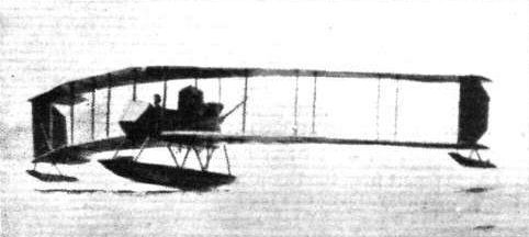
Mr. Astor's Burgess-Dunne leaving the water.
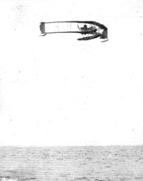
Mr. Vincent Astor's Burgess-Dunne seaplane in flight over Marblehead Bay.
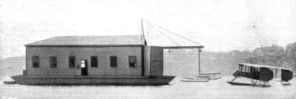
WATERPLANE SPORT IN AMERICA. The floating hangar which houses Mr. Astor's Burgess-Dunne seaplane.

Hoisting Mr. Astor's Burgess-Dunne seaplane into its floating hangar.

ONE OF THE U.S.A. GOVERNMENT BURGESS-DUNNE SEAPLANES. - This machine is somewhat smaller and faster than its predecessors. It has a Curtlss OX 100 h.p. motor, and the planes, which are staggered, fold together when dismantled.
Flight, April 30, 1915.
EDDIES.
IT seems that the Sperry gyroscopic stabilizer is going strong on the "other side." Partly by way of giving another demonstration of its capabilities and partly because he wanted to qualify for his "expert" certificate, the inventor, Mr. Lawrence B. Sperry, with Mr. Alan R. Hawley, President of the Aero Club of America, as passenger, took his Curtiss flying boat, which is fitted with the stabilizer, for a spin round Manhattan and the Statue of Liberty. They left the New York Navy Yard at Brooklyn, and soon rose from the water after passing Williamsburg Bridge. Following the course of the East River, the Harlem Ship Canal, and then the Hudson River, they flew over the Hudson to Ossining, where they circled several times, and then turned back. On the way down from the upper end of Manhattan Island, the craft had been flying about level with the top of the houses (no mean height in New York), but, on nearing the City, Mr. Sperry noticed that the air currents were growing more choppy, and so rose to a height of 500 ft. Down the river once more and into the bay sped the flying boat, quickly circling the Statue of Liberty. Then the craft steered over Brooklyn Bridge and, dipping under Manhattan Bridge, with little room to spare, alighted at the Navy Yard, from which it had started. The distance covered in the flight was 80 miles there or thereabouts.
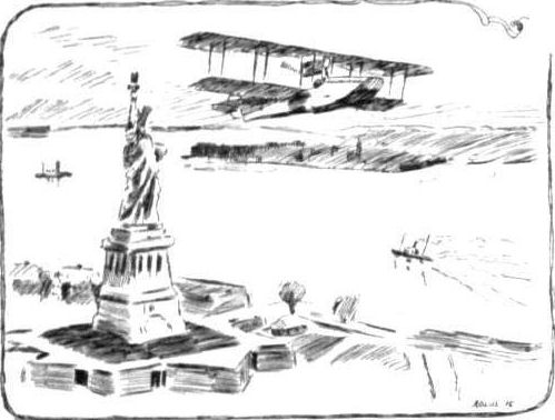
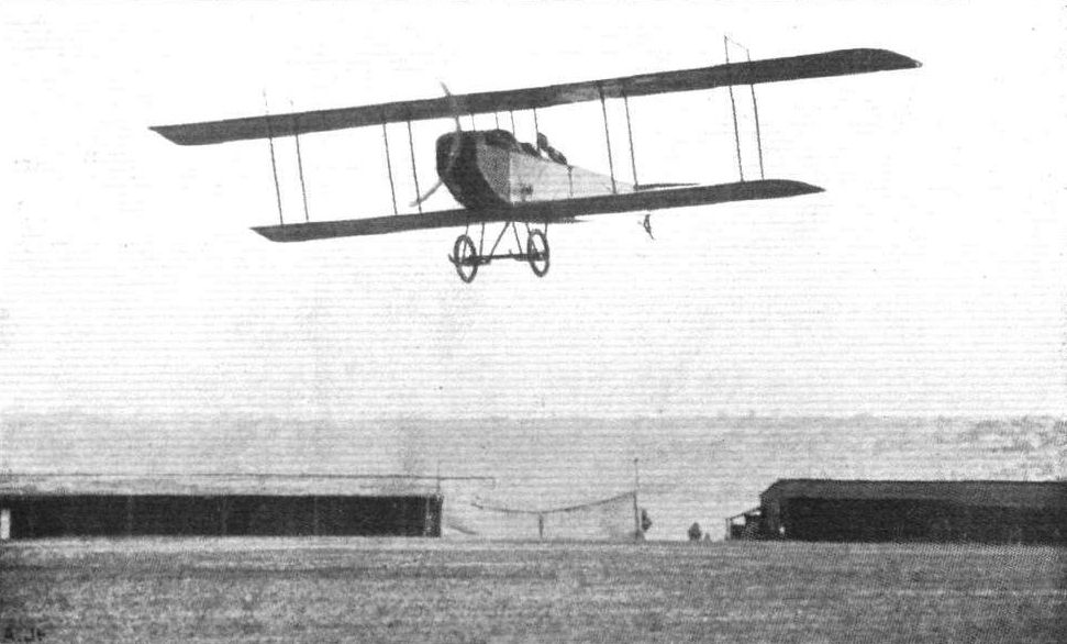
The latest Curtiss biplane, of which we gave details in our issue of December 11th, in full flight. With a 90 h.p. Curtiss motor this machine is claimed to have a speed range of from 40 to 90 miles per hour.
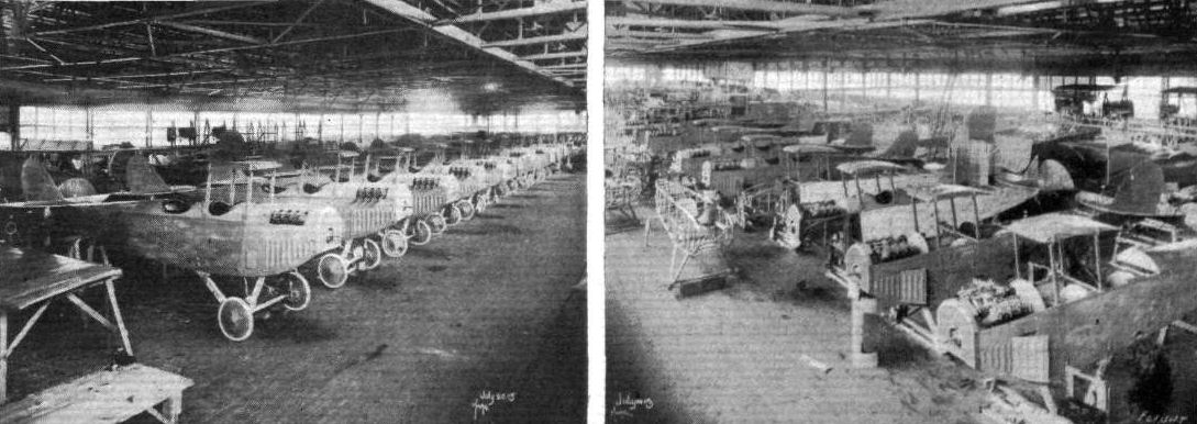
A batch of Curtiss fuselages, in various stages of completion, at the Curtiss works at Buffalo, N.Y.
Flight, May 7, 1915.
THREE NEW AMERICAN MACHINES.
FOR some time past there has been noticeable a certain activity among American aeroplane manufacturers, consequent no doubt upon the increased interest being taken by the U.S. Government in military aviation, which it is hoped will lead to the handing out of substantial orders very shortly. It is also not unlikely that some of the firms hope to do considerable business with European Governments, and it is interesting to notice how the general design of some of the latest machines approximates very closely to those which have proved most successful over here. This is clearly shown in the photographs which we reproduce of some military tractors that have recently made their first appearance, and passed their preliminary trials.
Although retaining a sufficient number of Curtiss characteristics to make her instantly recognisable as coming from the hand of this designer, the new Curtiss military tractor shows pronounced departures from its prototypes. In the latest machine, which has a Curtiss engine of 160 h.p., the main planes are set at a considerable forward stagger, whilst being straight as seen from in front, that is to say, having no dihedral angle. Ailerons are as usual hinged to the outer rear inter-plane struts instead of to the trailing edge of the upper plane, as is the general practice on this side of the "pond." Pilot and passenger are accommodated tandem fashion in the same cock-pit, and appear to be placed unusually far back, even allowing for the extra weight of the 160 h.p. engine. The chassis is, on the other hand, placed very far forward, supporting, in fact, the engine only, leaving the combined weight of pilot, passenger, controls and instruments unsupported, an arrangement which would seem to impose severe bending stresses in the body in a heavy landing.
<...>
Flight, August 27, 1915.
EDDIES.
With the alertness for sensing the ever-occurring changes in requirements, that is so characteristically American, and with their up-to-date methods of manufacture, that are typical of the Curtiss Aeroplane Company, and which enable them to meet these requirements, this firm have lately produced a machine which will be known as Model R, designed with a view to combine good speed and climb with weight-carrying capacity. This Curtiss military tractor is in its present form built as a three seater, the observers being placed approximately over the e.g., while the pilot sits well back in a separate cockpit slightly to the rear of the planes. The engine - a 160 h p. Curtiss - drives a three-bladed propeller, which, as in other types of Curtiss machines, is of comparatively small diameter, allowing a very low chassis to be employed. Judging from reports of the preliminary flights that took place at the firm's flying ground at Buffalo, N.Y., the new machine promises exceedingly well. In the first trip the pilot, Raymond V. Morris, accompanied by two passengers, Lieut. McIlvain of the Marine Corps and C. W. Webster of the Curtiss Aeroplane Co., climbed to a height of 8,200 feet in 27 minutes, which besides constituting an American altitude record, sounds pretty satisfactory.
***
Later in the day Morris was up again, this time accompanied by three passengers, and established another American record by reaching a height of 8,300 ft. Had it not been for the fact that the barograph took it into its head to cease barographing at this point, a considerably greater height would have been achieved. Experts who witnessed the flight, the official observer, who was one of the passengers, and the pilot all agreed, I understand, that the machine would have been good for another 4,000 ft. at least. When a new barograph, registering up to 25,000 ft., is ready, Morris and a passenger are to have a try at beating one or two world's records, not only the one of 6,170 metres, established by Lieut. Bier at Aspern in June, 1914, but also Oelerich's record of 8,150 metres for pilot alone, which he made at Lindenthal, Leipzig, in July, 1914. And, knowing how well the smaller Curtiss machines have climbed over here with Sydney Pickles at the helm, I shall not be in the least surprised either to see Morris getting ahead of the German record.
"AEOLUS."
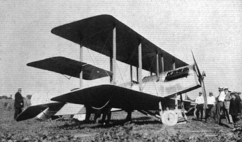
The new model R 2 at the Curtiss "Aerodrome," Buffalo, N . Y.
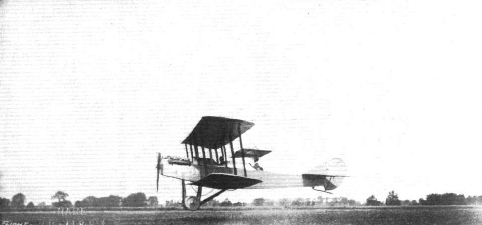
LANDING. - The 160 h.p. model R.2 Curtlss military tractor, which on its official test flight attained a speed of 90 m.p.h# and climbed to 8,200 feet in 26 minutes, with a load of 1,030 lbs., made up of four men, 4 hours' supply of petrol and oil, and sand to represent weight of bombs.
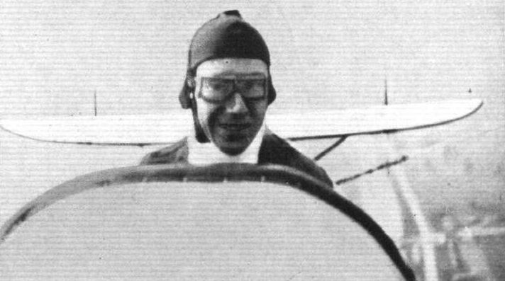
A short time ago reference was made in "Eddies" to the American height records established by the American pilot, Raymond V. Morris, on a Curtiss model R2 tractor biplane. The accompanying portrait of the pilot was taken by one of his passengers at an altitude of 8,000 ft.
Flight, May 28, 1915.
THE DAUGHERTY TRACTOR BIPLANE.
EARL S. DAUGHERTY, the well-known American pilot, who claims to have flown more types of machines than any other American pilot, is responsible for the design of the very "business-like-looking" machine shown in the accompanying illustrations and scale drawings. It was built for him at Chicago last winter by Max Stupar, and on it he has been making numerous successful flights at Long Beach.
It is a tractor biplane with swept-back wings, following the practice of certain German types, but otherwise it is more or less original in design. Special attention has been given to the quick assembling and dismantling of the various parts, so that it should be specially suitable for military or exhibition purposes. Top and bottom planes have a span of 38 ft. and 26 ft. respectively, whilst the respective chords are 5 ft. and 4 ft. The top plane is divided into four sections, consisting of two inner sections, 11 ft. span each, divided in the centre, and two outer extensions 8 ft. each. The inner ends of the centre sections are attached to two pairs of inverted V struts mounted above the body, and the two lower plane sections abut against the bottom longitudinals of the body, quick detachable fittings being employed. Four pairs of streamline spruce struts separate the top and bottom planes, which are 4 ft. 6 ins. apart, and cable is employed for bracing the same. The top attachment of the interplane struts, is by means of eye-bolts fixed to the spars, and the attachment to the lower plane is by quick detachable fittings which permit the withdrawal of the struts without interfering with the adjustment of the bracing. If required the top plane extensions can be replaced by small sections so as to give a total span of 26 ft., for speed work. The planes are built up on two spars, the front ones of D section, forming the leading edge and the rear ones of rectangular section, spaced 3 ft. 6 ins. from the former; both front and rear spars measure 1 1/4 ins. by 1 3/4 ins. The ribs are built up of spruce battens and webs, glued and nailed together, and fastened front and back to the spars by metal strips. They are spaced at intervals of about 1 ft., and have a maximum thickness of 1 1/4 ins. The wing section has a maximum camber of 31/4 ins. for the top plane, that of the lower plane being in proportion, situated at a point 30 per cent, of the chord from the leading edge. The whole wing framework is strongly braced with steel wire, and covered with linen treated with Emaillite. Hinged to the rear spars of the top plane extensions are the balancing flaps, which are interconnected. The tail planes consist of a fixed surface, 10 sq. ft. area, of very high aspect ratio, hinged to which are two elevator flaps of about 10 sq. ft. each, with a partly balanced vertical rudder mounted between them. The tail is protected by a rubber sprung skid.
The body is of rectangular section, divided into two portions to facilitate shipment. The longitudinals and struts of the front section are of ash, and those of the rear half are of spruce. The engine, a 50 h.p. Gnome, is mounted in the nose of the body, and partially enclosed by a metal cowl. Immediately behind the engine is the passenger's cockpit, and behind that again, at the rear of the trailing edge of the top plane, is the pilot's. The body is fabric-covered, at the rear half, whilst the fore-portion is covered with metal sheeting. The control is of the Farman type, consisting of a universally jointed lever for the balancing flaps and elevators, and a horizontal foot-bar for the rudder. For school work a dual control is provided, which can be disconnected by the pilot at will. The under-carriage consists of two curved laminated skids which are connected to the body at their rear ends, and two short struts, 22 ins. in length, forming a connection with the body at the forward ends. A pair of 28 in. wheels are mounted on a 1 7/8 in. tubular steel axle, which is attached to the skids by rubber shock-absorbers. The whole of the landing gear can be detached from the body by the removal of four 5/8 pins. The fuel tanks have a capacity of 15 gallons of petrol and 8 gallons of oil, and provision is made for an extra petrol tank in the passenger compartment.
On the dash in front of the pilot is a full range of instruments, such as barograph, gradometer, revolution indicator, and also switches for an electric searchlight to be used for night work. The weight of this machine comes out at about 540 lbs. empty. We understand that Mr. Daugherty has just recently had a demonstration of the strength of his machine through an accident at Long Beach. Owing to a mishap to the control gear whilst making a banked turn, the machine fell to the ground, landing full on the motor. In spite of this, the machine was not beyond repair, and will be flying again shortly.

Three-quarter front view of the Daugherty tractor biplane.
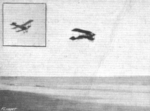
The Daugherty tractor biplane in flight at Long Beach.
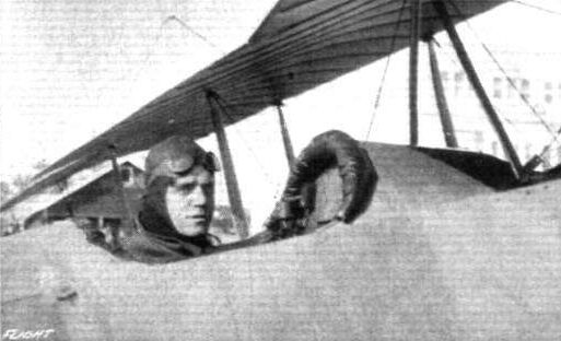
Earl S. Daugherty in the pilot's seat of his tractor biplane.
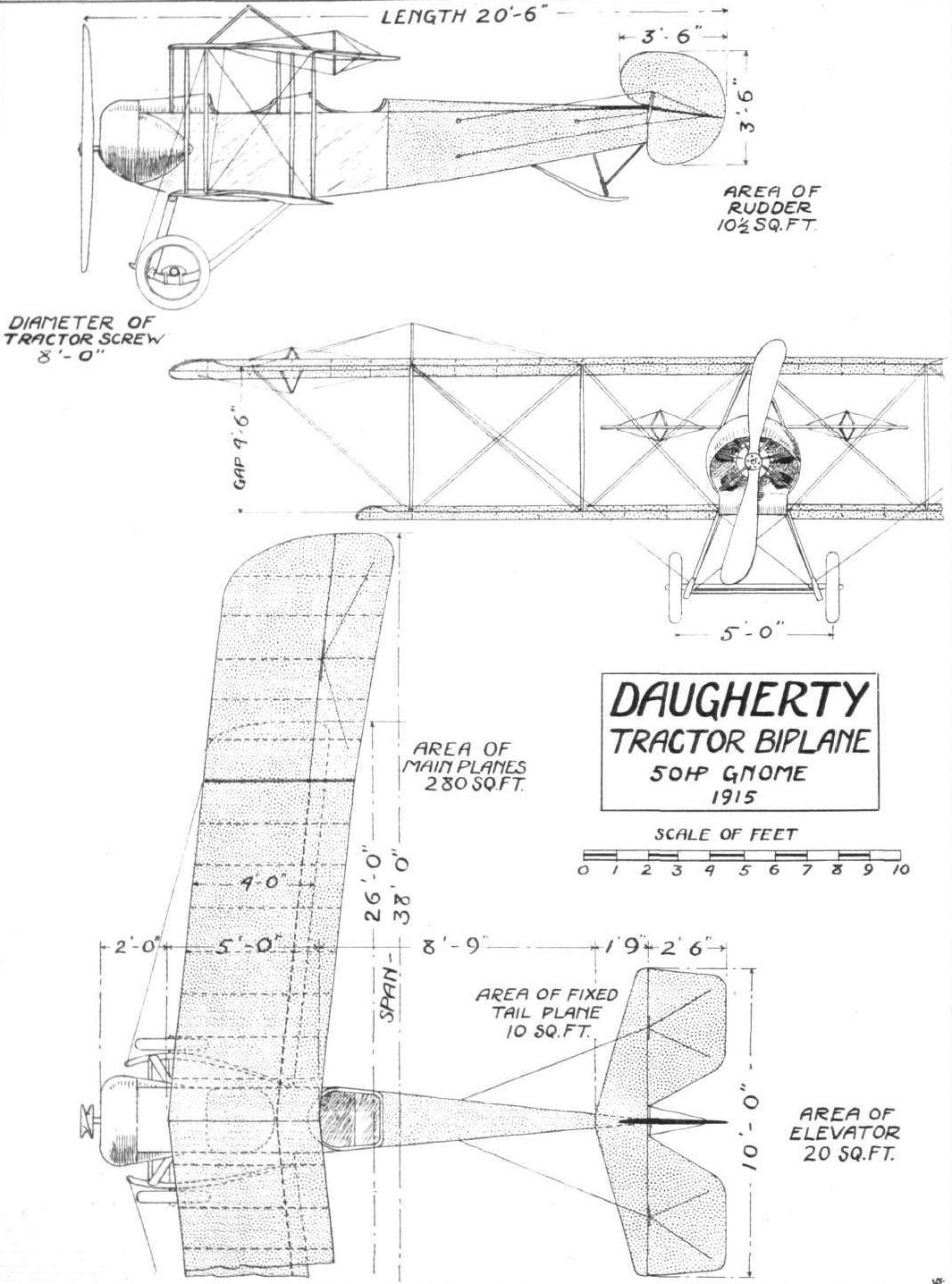
Plan, front and side elevation to scale of the Daugherty tractor biplane.
Flight, May 7, 1915.
THREE NEW AMERICAN MACHINES.
FOR some time past there has been noticeable a certain activity among American aeroplane manufacturers, consequent no doubt upon the increased interest being taken by the U.S. Government in military aviation, which it is hoped will lead to the handing out of substantial orders very shortly. It is also not unlikely that some of the firms hope to do considerable business with European Governments, and it is interesting to notice how the general design of some of the latest machines approximates very closely to those which have proved most successful over here. This is clearly shown in the photographs which we reproduce of some military tractors that have recently made their first appearance, and passed their preliminary trials.
<...>
In the Gallaudet military tractor biplane the influence of German designing practice can be clearly traced in the backswept main planes and upturned ailerons. The arrangement of the fuselage is somewhat reminiscent of the Handley Page biplane in the manner of carrying the lower plane right across instead of attaching the two halves of it, as it is done in most machines, to the sides of the body. Also in the covering of the body is German influence noticeable, as this takes the form of three-ply instead of the usual fabric covering. The chassis is of the Vee-type, having the rear members continued forward in the form of tusks or short skids. The engine is a 50 h.p. Gnome, which it is intended later, we understand, to replace with a Gyro.
A hemispherical nose-piece encloses the centre part of the propeller so as to form a good entry for the air. During the first flight of this machine the pilot, Mr. Harold Kantner, is said to have felt so confident in the stability of his mount that he let go of the controls and made a prolonged flight with his hands raised above his head.
<...>
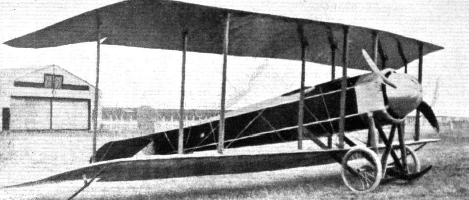
The new Gallaudet military tractor biplane.
The Gallaudet in flight.
Flight, March 12, 1915.
AN AMERICAN "PARASOL" MONOPLANE - THE GRINNELL.
IN general design, several of the latest aeroplanes built in the United States have followed, more or less closely, European practice. From this it must not be inferred that they lack originality, for the latter is to be found in constructional details, whilst in some cases traces of American practice still remain. One of these "European" models that has given very satisfactory results is the Grinnell monoplane, designed by William C. Robinson and built by the Grinnell Aeroplane Co. of Grinnell, Iowa. This machine is of the "Parasol" type, i.e. having the mounted above the body, a practice introduced little time back by the Morane-Saulnier and Bleriot firms, which has proved its worth on active service. The principal advantages of this type are an increased range of vision, and, so it has been claimed, an improvement in stability. The Grinnell parasol differs from the Morane-Saulnier and Bleriot machines of this type in that the wings are not all in one piece, but in two sections, leaving an open space in the centre above, and of about the same width as, the body. By this arrangement an unobstructed view upwards is obtained, and in this respect it is certainly an improvement, but it would be interesting to know if the space in the centre of the wings has any effect aerodynamically. The wings, which are rectangular in plan-form, are supported above the body by two pairs of short tubular struts. The front and rear pairs of these struts are each connected to a horizontal tubular member which receives the inner ends of the front and rear wing-spars respectively - forming, in fact, continuations of the spars. Four tubular extensions of the short struts form a pyramid above the wings from which the latter are braced. The rectangular body is not unlike that of the Nieuport monoplane, and in the nose is mounted the 100 h.p. engine. The latter is also of Robinson's own design, and is a 6-cyl. radial (fixed) air-cooled engine having a bore and stroke of 5 ins. and 6 ins. respectively. Behind the engine are the fuel tanks, and behind these again are the pilot's and passenger's seats, arranged side by side. The front portion of the body forward of the cockpit is covered with sheet aluminium, and the remainder with fabric. The tail consists of two almost rectangular stabilizing surfaces, mounted on either side of the rear extremity of the body, with elevator flaps hinged to the trailing edges. A peculiar feature of the stabilising surface is that the leading edge is curved forwards where the abutment against the body takes place, so that a kind of peak is formed. Pivoted to the sternpost of the body is a circular-shaped partially balanced vertical rudder
The under-carriage is both simple and strong. It consists of two tubular steel U struts, to the lower extremities of which are sprung the two running wheels. The front under wing-bracing cables are anchored to the forward members of the U struts, whilst the rear under bracing or warp cables are carried by the lower longitudinals of the body. It was on this machine that W. C. Robinson put up the American cross-country record last October (375 miles in 4 hrs. 44 mins.). The principal dimensions of the Grinnell monoplane are :- Span 35 ft.; chord 7 ft.; supporting area 225 sq. ft.; overall length 25, ft.; weight empty 900 lbs.; speed about 80 m.p.h.
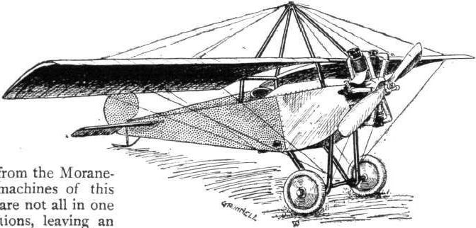
Flight, May 7, 1915.
THREE NEW AMERICAN MACHINES.
FOR some time past there has been noticeable a certain activity among American aeroplane manufacturers, consequent no doubt upon the increased interest being taken by the U.S. Government in military aviation, which it is hoped will lead to the handing out of substantial orders very shortly. It is also not unlikely that some of the firms hope to do considerable business with European Governments, and it is interesting to notice how the general design of some of the latest machines approximates very closely to those which have proved most successful over here. This is clearly shown in the photographs which we reproduce of some military tractors that have recently made their first appearance, and passed their preliminary trials.
<...>
Like the Gallaudet machine, the Heinrich military tractor may be said to belong to the "Arrow" type, having slightly back-swept main planes, of which the upper has a pronounced overhang.
These extensions are braced in a downward direction by cables running to the lower ends of the outer pair of interplane struts, but no provision has been made, it appears, for bracing them upwards either by means of king posts or some similar arrangement.
The body is of rectangular section, and is armoured in front so as to protect, as far as possible, the engine, observer, and pilot.
With the new 110 h.p. Gyro motor, which is, by the way, the first motor of that type to be delivered, a speed of 46 to 90 m.p.h. is anticipated, a very good speed range for an armoured machine. For a span of 35 ft. and a length of 24 ft. 6 ins., the machine has a weight of 950 lbs.
Flight, July 16, 1915.
THE HEINRICH MILITARY TRACTOR BIPLANE.
DESIGNED primarily with the intention of meeting the U.S.A. Army's and foreign governments' requirements, prominent amongst which may be mentioned fast climbing, good speed range, and general stability, the Heinrich tractor biplane is an interesting example of recent American practice. It must be admitted that this machine certainly possesses more originality in design than some of the military machines lately turned out away yonder. Heinrich Brothers, of New York, have been constructing monoplanes for several years now, and this machine, which, by the way, was designed and constructed in record time, is their first biplane. As far as actual performance goes the Heinrich biplane put up a decidedly good show on the first time of asking, when Albert S. Heinrich, accompanied by Mrs. Heinrich, climbed it at the rate of about 1,000 ft. per minute. Subsequent flights brought out further favourable points - a speed range of 45 to 80 miles per hour, climbing speed with pilot and passenger and fuel for four hours of 4,000 ft. in 10 minutes. Flying light, a speed of 90 miles per hour has been attained. We believe large-works have been taken over by the Heinrich Company for the purpose of building these machines to the order of one of the European Governments.
Two of the outstanding features of the Heinrich biplane are the short and very broad body, accommodating the pilot and two passengers - side by side - and the swept-back wings. The latter are virtually in four sections, the top plane being in two and attached to a small central panel mounted above the body by four struts, and the bottom plane in two attached direct to the body. Each section is built up on two main spars of I section, the webs being of ash and the flanges of spruce. The front spars are situated 9 ins, from the leading edge, and about 2 ft. 9 ins. from the rear spars. The ribs, which are spaced 9 ins. apart, are built up of ash webs and spruce flanges, reinforced where the interplane struts are attached to the planes. Laminated four-ply ash is employed for the wing tips, which are rounded off Morane fashion. The top plane is staggered forward 9 ins., and both top and bottom planes are inclined backwards 5#. Each top and bottom section is separated by two pairs of struts, and ailerons measuring 8 ft. 3 ins. by 2 ft. are hinged to the rear spars of the top plane only. The whole of the framework is covered with unbleached Irish linen, doped with a special grey varnish. The tail planes consist of a triangular stabilising surface in two sections, one mounted on either side of the body, two elevator flaps, and a balanced rudder in between the latter. Two types of control can be fitted, either the Deperdussin type, consisting of wheel and rocking column for ailerons and elevators respectively, with footbar for the rudder, or else a "three-in-one" control. Dual control is also fitted if required.
The body is of rectangular section, 3 ft. 4 1/2 ins. wide by 2 ft. 9 ins. deep in front, tapering at the rear to a horizontal knife edge 13 ins. wide. The longitudinals are of ash tapering from 1 1/2 ins. square to 1 in. square. There are seven sets of stout channelled ash struts, which together with wire cross-bracing, make for a strong box-girder of the whole body. The second and third pairs of vertical struts are made extra stout to carry the four struts supporting the top plane, and are slotted at their lower ends to receive the ends of the lower plane spars. On the top of the body is a turtle deck providing a good stream line, which is further preserved by almost totally enclosing the engine by an aluminium cowl. Slots are cut in the front of the latter in order to allow air to enter and circulate round the engine. The aluminium covering is carried back to just forward of the passengers' cockpit, aft of which the body is covered with fabric doped the same as the planes. The engine, a 110 h.p. 8-cylinder Gyro rotary, weighing 270 lbs. - the first of this horse-power to be turned out - is mounted in the nose of the body with both front and rear bearings, the front and rear mountings being of 3/32 in. reinforced steel, whilst the struts carrying the rear mounting are extra large (2 ins. by 3 ins.) and unchannelled. Coupled direct to the engine is a tractor screw 8 ft. diameter by 6 ft. pitch. Petrol and oil are fed to the engine by gravity from a service tank holding 15 gallons of petrol and 10 gallons of oil in front of the pilot's seat. The petrol service tank is supplied with petrol from a 25 gallon tank under the pilot's seat by pressure, a hand pump also being fitted for use should the pressure feed fail. The petrol and oil consumption of the 110 h.p. Gyro is said to be 10 gallons and 11/4 gallons per hour respectively.
A simple but strong under carriage is fitted, consisting of two skids connected to the body by four ash struts measuring 1 1/4 ins. by 3 ins., and a pair of 26 ins. by 4 ins. disc wheels. The skids are of 5-ply laminated hickory, 4 ft. 6 ins. long, 2 1/2 ins. deep by 2 ins. wide, turned lip in front and projecting forward to protect the tractor screw. The axle is attached to the skids by rubber shock absorbers. The whole of the chassis is cross braced by wire, and two steel tubes.

The armoured Helnrich military tractor equipped with a 110 h.p. Gyro motor.
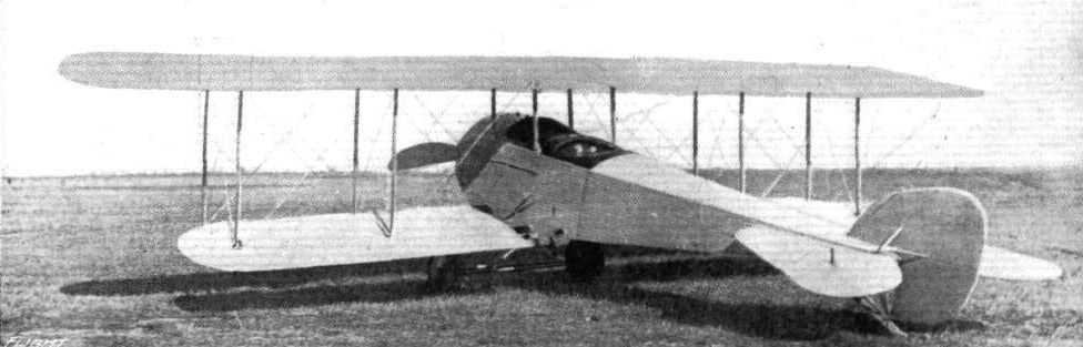
Three-quarter view from the rear of the Heinrich military tractor biplane.
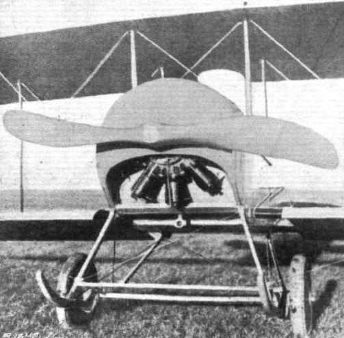
View showing the 110 h.p. Gyro engine mounted in the Heinrich military tractor biplane.

Diagram showing the wing section of the Heinrich military tractor biplane.
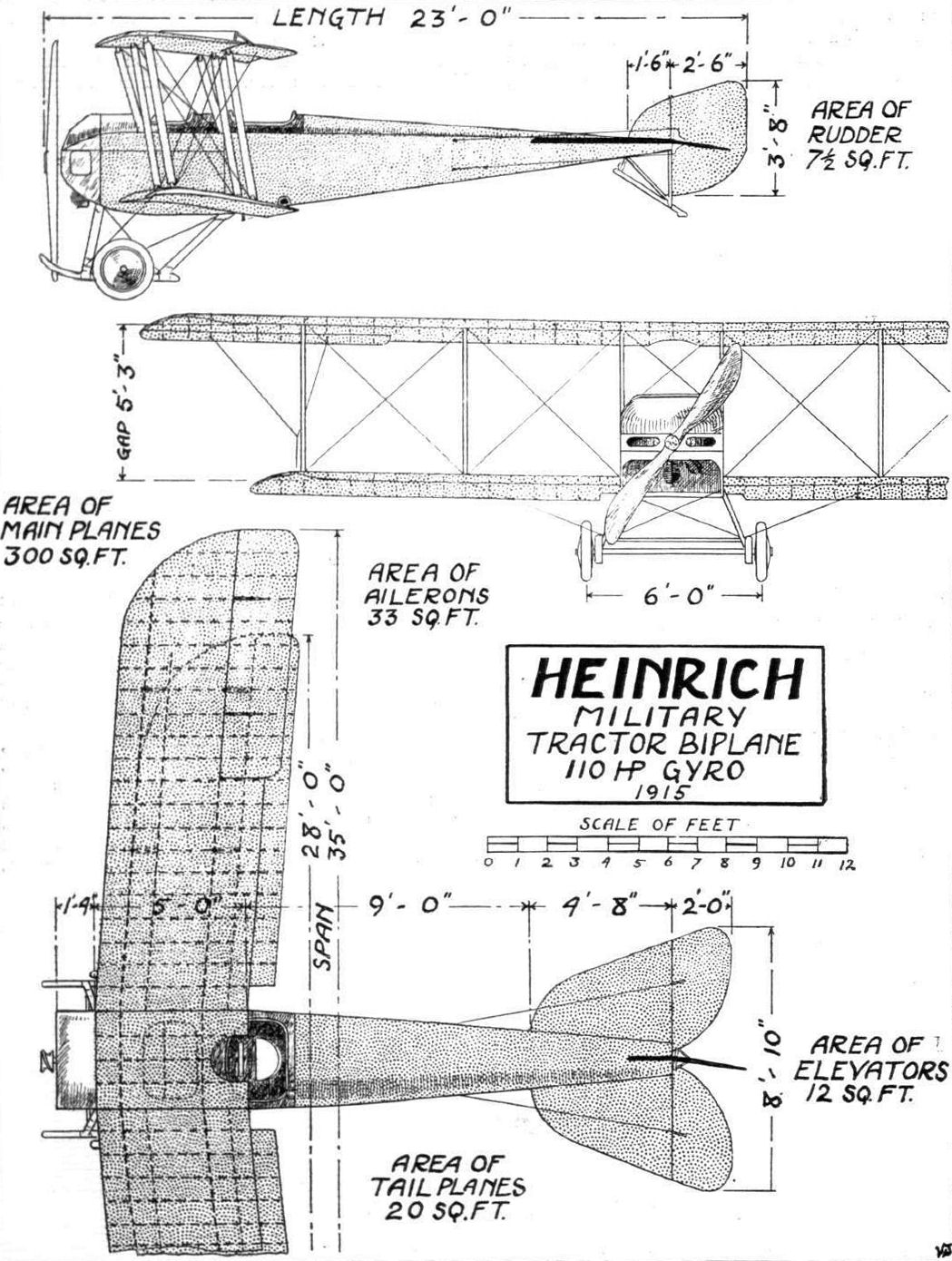
THE HEINRICH MILITARY TRACTOR BIPLANE. - PIan, side and front elevations to scale.
Flight, July 23, 1915.
THE HUNTINGTON TRACTOR BIPLANE.
THE Huntington tractor biplane, which made its first appearance last March at Hempstead Plains, U.S.A., has been constructed to the designs of H. P. Huntington by Harold Kantner, whose name is no doubt known to our readers in connection with the Kantner-Moisant monoplane. From accounts of trials it appears that the Huntington is a very efficient machine, the speed range, fully loaded, being claimed to be from 45 to 76 miles per hour, although it is fitted with an engine of but 80 h.p. and is by no means a small machine, being 36 ft. span. Both top and bottom planes are of the same span, but the top plane is staggered forward 1 ft 3 ins., and is given an angle of incidence of 4°, whilst that of the lower planes is 2 1/2°. The wing section is very similar to that of the Nieuport, in that the leading and trailing edges are slightly upturned, but in the Huntington there is a little less camber. The planes are built up much in the ordinary way on two main spars, the front one being situated 9 ins. from the leading edge and the rear one 1 ft. 3 ins. from the trailing edge. The spars are of I-section, except at the junctions with the interplane struts, where they are solid and of rectangular section. A neat and simple method of attaching the interplane struts to the spars is employed, whereby the latter are not pierced. Two steel plates, one bent to a U, are clamped to the main spar by two 3/16 in. Bleriot type U bolts, which pass over the plates and around the spar. The U plate receives the end of the strut, on which is a steel ferrule having notches cut in it to clear the U bolt, and the strut is held in position by a bolt passing through it and the U plate. The ends of the second plates are bent up and serve as anchorages for the wire bracing turnbuckles. Between these two plates and the spar is a fibre angle piece which brings the socket and the strut into the correct alignment, and obviates the necessity of cutting the ends of the struts at different angles. The bottom plate is in two parts and is attached to the second and third main body struts, which are of oval section steel tube. The top plane is in three parts, the two outer portions being attached to a small central panel which is supported above the body by four struts. Two pairs of struts on either side of the body separate the top and bottom planes. Hinged to the rear members of these struts, midway between the planes, are the balancing flaps. These are controlled by a single cable which is attached to the top of the flaps only. Rubber cords anchored to the rear spar of the lower plane are attached to the under sides of the flaps, so that when one is pulled up the slack of the cable to the other is taken up by the pull of the rubber cord and this flap is thereby pulled down. In this way a double acting or interconnecting arrangement is obtained. The tail planes are similar to those on the Nieuport, consisting of a semicircular stabilising surface, to the trailing edge of which are hinged two similarly shaped elevators. The rudder, however, differs from that of the Nieuport, being nearly rectangular in shape with a small surface forward of the pivoting axis. All the tail planes are constructed of steel tubing braced together. The body is also similar to that of the Nieuport, being of rectangular section, very deep in the vicinity of the pilot's cockpit. The body is built up of wood, except for the first three struts, which are of oval section steel tubing. The whole of the body is covered with fabric, except for the front portion forward of the cockpit, which is covered with sheet aluminium. The engine, an 80 h.p. 7-cyl. Gyro, is supported by front and rear mountings in the nose of the body, large openings being cut in the front of the aluminium cowl for cooling purposes. Behind the engine is the pilot's seat, immediately behind which is that for the passenger, who sits close up as in the Morane Saulnier. The control is of the usual wheel and rocking column, and rudder-bar type. The undercarriage is a modified Nieuport type consisting of a central tubular steel skid attached to the body by three pairs of V streamlined section steel struts, and a pair of wheels attached to a laminated steel spring mounted in the centre of the central skid. Two auxiliary spiral springs mounted within telescopic tubes, extending from the body to the stud axles, add greatly to the steadiness of the machine when taxying on the ground. The weight of the machine empty is 925 lbs.
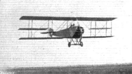
The Huntington tractor biplane in flight.
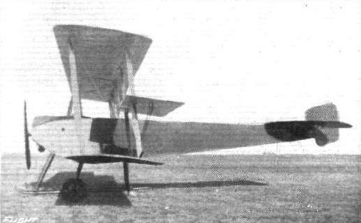
Side view of the 80 h.p. Huntington tractor biplane.
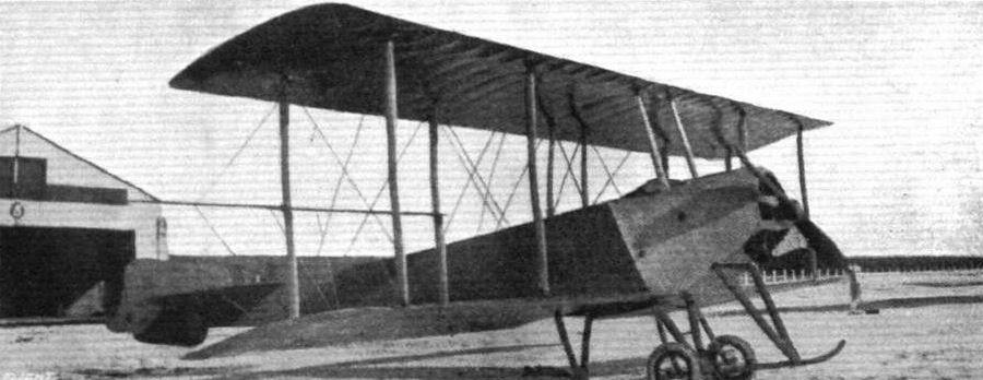
Three-quarter front view of the 80 h.p. Huntington tractor biplane.
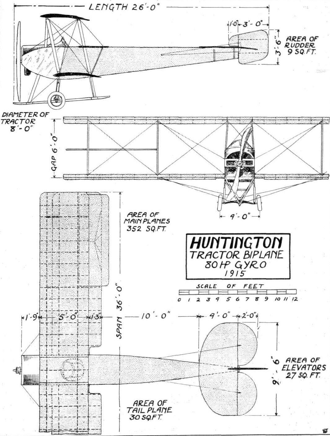
THE HUNTINGTON TRACTOR BIPLANE. - Plan, side and front elevation to scale.
Flight, June 25, 1915.
THE JANNUS FLYING BOAT.
WHEN the Jannus brothers, Antony and Roger, who made their names as pilots of those successful flying boats built by the Benoist Company, announced last year that they were going to start on their own account, and design and construct flying boats, it was realised that their experience should result in the production of a very useful craft. It is not surprising, therefore, that now the first product of the Jannus firm has made its test at Baltimore it has more than fulfilled expectations.
Although the Jannus machine appears to follow the usual lines of flying-boat design, there are, as a matter of fact, many original features embodied in its design, mostly as regards construction. The principal objectives of the designers have been sea-worthiness, wide range of speed, quick assembling and dismantling, comfortable and clean accommodation for pilot and passengers, and general efficiency. As regards the former item, tests have shown that there is little to be desired in this respect. This has been brought about by the low centre of gravity and the large freeboard, as well as other points in the design of the hull. In addition, the special form of wing tip floats assists largely in this matter. These taper sharply towards the bottom, reducing the planing surface at high speeds, so that there is little or no pounding action on the wings. At the same time, when acting as floats, they quickly displace the water at an increased rate, and overcome any heavy side load.
The hull, which is of the single step type, is divided into two portions, a fore portion containing the pilot, passengers, engine and main planes, and a rear detachable portion carrying the tail planes. This possesses advantages not only in construction, but in facility for shipping. The control cables from the cockpit to the tail all pass through a steel conduit which protects them against the propeller breaking, whilst they are provided with the Jannus sister hook, which locks them together quickly so that their adjustment is not affected when the tail is detached. The fore portion of the hull has a beam of 46 ins. at the top, tapering to 38 ins. at the bottom. The latter is concave at the step, after which it is slightly convex, curving upwards at the nose. A turtle deck in the bows protects the pilot from wind and spray. Behind the pilot's seat is a wide seat for three passengers, who have plenty of leg-room - in fact, the cockpit is exceptionally roomy. Immediately behind is the engine compartment, which is isolated from all other parts of the boat so that any oil or grease is confined to this compartment. The engine, a 120 h.p. 8-cylinder water-cooled Maximotor mounted fairly high up in the hull, drives by means of a chain the propeller, which is situated at the trailing edge of the planes and is mounted directly on the boat, being quite independent of the planes. This is quite an important feature, for should the planes through any cause become strained, the propeller and engine do not get out of alignment, and, again, the planes can be taken down without interfering with the power plant. The rear portion of the boat tapers from the section of the fore-hull to a shallow vertical knife-edge at the rear.
The planes, which form a complete unit, are of rectangular plan form, having a span top and bottom of 45 ft. 10 ins., a chord of 5 ft. 6 ins., and a gap of 6 ft. The top plane is staggered forward about 18 ins. Perhaps the most interesting feature is the interplane strut construction. These struts are arranged in six pairs, the fore and aft struts of each pair being situated only some 18 ins. apart, and both are enclosed in a fabric covering. Each pair is thus effectively streamlined - a similar practice to that carried out on the Avro-Arrow scout and the D.F.W.-Arrow scout. Besides increased efficiency, this construction makes for strength, each pair of struts being braced by horizontal struts and wire bracing. The struts being mounted in the main spars, the latter are necessarily situated in the centre of the planes the same distance apart as the former, but being strongly cross-braced in between the spars, the whole frame is by no means weak; wood battens form the leading and trailing edges. A balancing flap measuring 6 ft. by 2 ft. is hinged to each outer extremity of the rear spars of both top and bottom planes. The tail planes consist of a fixed stabilising surface 12 ft. span by 2 ft. chord, to the trailing edge of which are hinged two elevators of 13 1/2 sq. ft. area each. In between the latter is a partially balanced rudder, connected with which at the stern of the boat is a small water rudder. The horizontal surfaces are mounted some 3 ft. above the boat. The control fitted is of the Jannus two-lever type, consisting of one lever operating the balancing flaps and another lever operating the elevators and rudder.
During the tests, which were carried out by Mr. F. G. Ericson and Mr. Antony Jannus, a total load of 2,200 lbs. was carried at a speed varying from 30 to 55 miles per hour with only 60 indicated h.p., so that with full power great things may be expected. The principal dimensions of the Jannus flying boat are: Span, 45 ft. to ins.; chord, 5 ft. 6 ins.; gap, 6 ft.; supporting area, 480 sq. ft.; length over all, 28 ft.; length of hull, 25 f t ; weight of machine empty, 1,665 lbs.; useful load, 900 lbs.; range of action loaded, 240 miles.
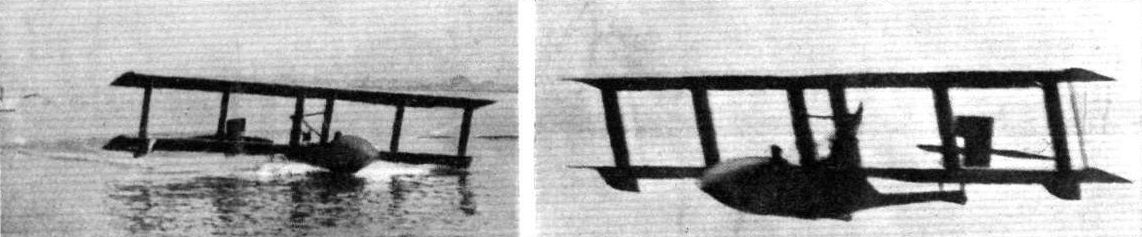
Two views of the 120 h.p. Jannus flying boat. - On the left, leaving the water; and on the right, in flight.
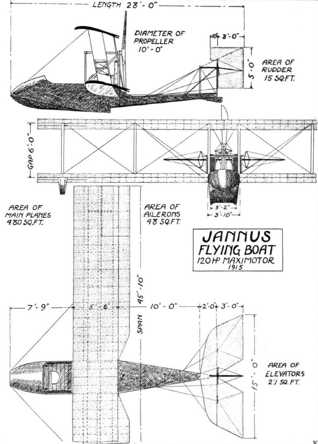
Plan, front and side elevation to scale of the Jannus 120 h.p. flying boat.
Flight, July 9, 1915.
EDDIES.
HUNTING wild game from an aeroplane is a sport which appears to be in a fair way to become popular with our cousins on the other side. The hilly country near Rosco, California, has been the scene recently of several hunting parties of this description, the sharpshooter being Fred Mills and the man at the wheel the well-known California pilot Glenn Martin. The plane used was one of the Martin tractor biplanes. Circling round over the surrounding country in wide circles at a height of 3,000 ft., Mills studied the ground below through his field glasses, and soon discovered a prowling coyote and his mate stalking a covey of quail. Shutting off the engine, the party glided down to within a hundred yards of the unsuspecting coyote, the machine was brought to an even keel, and Mills, leaning out of his cockpit and steadying himself against one of the inner plane struts, struck the animal down with a well directed shot. A similar fate overtook the other coyote. While the aviators were walking about picking up the dead animals a third unwisely approached within range and was promptly added to the bag. It appears that so noiseless had been the approach of the hunting party coming down in a glide with the engine cut off that the animals in the nearest vicinity of the landing place had heard nothing, and before starting for home the hunters were able to shoot a couple of bobcats, which were loaded on board with the rest of the game. In America when they are out for sport they are out some.
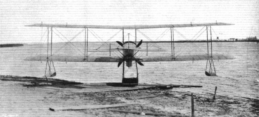
An American seaplane. - One of Glenn Martin's latest machines equipped with a 125 h. p. Hall-Scott 6-cyL motor. This seaplane is said to be capable of lifting a useful load of 1,000 lbs., and to bave a radius of action of 525 miles.
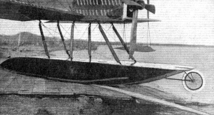
In a recent issue we published a photograph of one of the latest American seaplanes - the Glenn Martin. In the accompanying illustration is shown more clearly the wheel which is mounted on the main central float to prevent the machine from turning over on its nose when running up on the slipway after a flight.
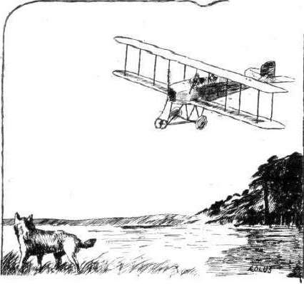
Flight, July 30, 1915.
THE 90 H.P. MAYO MILITARY TRACTOR BIPLANE.
FOLLOWING the lead of the more important firms, most of the concerns, both old and new, building aeroplanes in the United States are turning their attention to military tractor biplanes, which, judging from their performances, have demonstrated that our American cousins intend seriously to compete with European practice in this line. One of the most recent machines of this type to make its appeance is the Mayo biplane, designed by Chance M. Vought, whose work is well known in the American aviation world. Its first trials, under the pilotage of Stevenson MacGordon, were made at Pratt Field, Newhaven, Conn., and afterwards further trials were carried out at Garden City Aerodrome, Long Island. On this latter occasion a speed of 78 miles per hour is said to have been attained, whilst the climbing powers of the machine were also remarkably good, in spite of the fact that the tractor screw employed was not quite suitable. Simplicity and a minimum number of parts, quick assembling and dismantling, and other important requirements for military work, are features that have been studied in the design without sacrificing strength. In fact as regards the latter point, although the machine is certainly not on the heavy side, weighing empty 1,235 lbs., it comes out very well. A uniform factor of safety of 11 is employed throughout, with the exception of members where big strains and wear obtain, in which case the factor of safety is proportionately increased. Oversize wire cross bracings are also employed in order to minimise excessive elongation, causing mal adjustment, and the consequent need for frequent adjustment. Another feature that makes for strength is that in no case is a compression or load member pierced by bolts or pins, and none of the metal parts are welded. In short, the makers claim in their machine a high standard of workmanship and the best of materials - raw and finished materials for the first machine were tested in the laboratories of the Sheffield Scientific School, Yale University.
The upper and lower planes are of equal span, 38 ft., and are made up of four similar units and a small central panel mounted above the body by four struts, to which the two upper plane portions are attached. The lower plane units are attached to the bottom longitudinals of the body by means of four quick detachable heavy nickel steel pins. The inter-plane struts (four pairs) and bracing cables are anchored in quick detachable fittings with chrome nickel steel pins provided with safety chains. Both top and bottom planes are set at a slight dihedral angle, and the top plane is staggered forward 1 ft. 3 ins. in advance of the other. To improve the pilot's view above and below, portions of the planes are cut away in the top central panel and in the lower plane on either side of the body respectively. The main spars are of ash, and are of ample proportions. The front ones are situated some 6 ins. from the leading edge, whilst the rear spar is nearly 2 ft. from the trailing edge. The ribs, which are spaced about 1 ft. apart, are rigidly attached to the spars and only carry load stresses. A system of internal struts and wire cross bracing serves to take all compression strains. The wing section employed has been designed to give large lift combined with a wide speed range. Balancing flaps are hinged to the rear spars of both top and bottom planes, and the cables operating them are concealed within the planes. The gap between the flaps and the planes has been reduced to a minimum, so that there is little, if any, drag and loss of efficiency thereby. High grade linen, doped with Gallaudet varnish, is employed in the covering of the planes and other surfaces. The tail consists of a fixed non-lifting surface, semi circular in shape, to the trailing edge of which are hinged two elevator flaps, in between which is a vertical rudder. Forward of the latter is a vertical triangular fin. All these members, which are constructed of heavy gauge steel tubing, are secured to the body by a neat and safe arrangement, whereby they can be removed there from merely by withdrawing three bolts.
The body presents a very good streamline, being rectangular in section, tapering to a vertical knife-edge at the rear, and having a turtle deck. It is built up in two sections, of ash longitudinals and struts in the forward portion and spruce in the rear, the whole frame being well braced with heavy gauge wire, whilst the joints are all connected by means of specially-designed steel fittings, which obviate the necessity of piercing the longitudinals. The 7-cylinder 90 h.p. Gyro engine is mounted on two steel beds rigidly secured to the longitudinals in the nose, and is partially enclosed by an aluminium cowl. Immediately behind the engine are the fuel tanks, having a capacity for four hours' flight, and behind these are the passengers' and pilot's cockpits respectively. Forward of the cockpits the body is covered with sheet aluminium, the remainder being covered with fabric. The seats are provided with an arrangement for quickly adjusting their height. The Deperdussin type of control is fitted - a vertical wheel for lateral balance on a rocking column actuating the elevator, and a foot-operated rudder bar. The under-carriage consists of two ash skids connected to the body by three pairs of hollowed struts, and a tubular axle, sprung from the skids, carrying a pair of 26 in. by 4 in. wheels.
The principal dimensions of the Mayo tractor biplane are: Span, 38 ft.; chord, 5 ft. 6 ins.; gap, 5 ft. 3 ins.; supporting area, 374 sq. ft.; overall length, 27 ft.; weight, empty, 1,235 lbs.; speed, 43 to 80 miles per hour, with a landing speed of 36 m.p.h.
Flight, August 6, 1915.
THE "SIMPLEX" (MAYO) TRACTOR BIPLANE.
FURTHER particulars of the 90 h.p. Mayo type A reconnaissance tractor biplane which was described, with scale drawings and illustrations, in last week's Flight have since come to hand from America. It is stated that in view of the success of the first machines it has been decided to change the name to the "Simplex," and a separate company - the Simplex Aircraft Co. - has been organised for the purpose of building this and other types of aeroplanes and accessories on a large scale. Extensive works with an up-to-date equipment have been erected at a convenient site at New Haven, Conn., and one of the accompanying illustrations gives a fair idea of the extent of the new factory.
In addition to the type A military tractor biplane, two other types of military biplanes, both designed by Mr. Chance M. Vought, are being constructed. These are a single seater tractor scout, having a speed of 110 m.p.h., and a 175 h.p. gun-carrying pusher of somewhat large dimensions. It may be noted in passing that the high speed scout is a modification of a machine that was designed by Vought for the Aero Club of Illinois as an entry in the 1914 Gordon-Bennett race, unfortunately cancelled on account of the war.
Since its initial trial, on May 14th last, we understand that the model A tractor biplane has made nearly 200 flights, many of which have been made with a view to bringing out any weak points in design, as well as to demonstrate its flying qualities before various officials. Apparently no serious defects or deficiencies were brought to light, for it was not found necessary to make any alterations to the designer's original blue-prints, and no changes are contemplated; nor had a single wire or part been broken or replaced. The only items that have received attention are the shock absorbers on the landing chassis, which have been fitted with additional strands of rubber, and the fuel tanks, which have been enlarged. The tests further demonstrated that the machine was up to its designer's expectations as regards speed - the tests showed 3 m.p.h. more than was calculated - load carrying and climbing, with a fair margin to spare. We are informed that during the tests the machine made consistent speed averages of 83 m.p.h., and climbed 3,650 ft. in 7 mins., carrying a load of 645 lbs. including pilot and passenger. The minimum speed has not been absolutely determined owing to the unsuitable nature of the flying ground, but low speeds of 40 m.p.h. have been obtained. The best gliding speed of the machine, as measured by the air speed indicator, is 61 m.p.h., and the most efficient gliding angle is 1 in 7. As nearly as was determined, the best air speed for a full load climb was 65 m.p.h. These figures were obtained with the Ogilvie air speed indicator, working in conjunction with several other instruments of Mr. Vought's own design.
A glance at the illustration of the partly assembled fuselage, and also that of the wing frame, will reveal several interesting constructional details. For instance, in the case of the latter illustration, it will be seen that the ribs, which are constructed of 3-ply birch and mahogany, are not called upon to carry any compression stresses, functioning solely as load members. There are, however, three stout cross-struts between the spars which, together with the wire bracing, take all compression stresses. It will also be noticed that the spars are of substantial proportions, channelled out for lightness at intervals, and that the trailing edge is of steel tubing. Note should also be made of the steel fittings at the various joints, &c, which obviate the piercing of the spars and other members. The control arms for the rudder, elevators and ailerons shown on the left of the illustration in question are die stampings from special sheet steel.
The method of mounting the 90 h.p. Gyro engine between two steel beds rigidly secured to the fuselage longitudinals is clearly shown in the other illustration, whilst a good view of the control may be obtained. All the moving members of the latter have ball-bearing shafts, wheels and pulleys. As in the case of the planes, steel fittings are to be found connecting the various members, so that nowhere are the longitudinals pierced. The fittings attaching the chassis struts to the body are of the quick detachable type, so that the chassis can quickly be dismantled. In fact, quick detachable fittings are largely used throughout the machine, and the time taken to assemble from crates is claimed to be 28 minutes, 20 minutes being required for dismantling.

Side view of the 90 h.p. Mayo tractor biplane.

A view from the front of the 90 h.p. "Simplex" (Mayo), type A, reconnaissance tractor biplane.

Another view of the 90 h.p. "Simplex" (Mayo) reconnaissance tractor biplane.
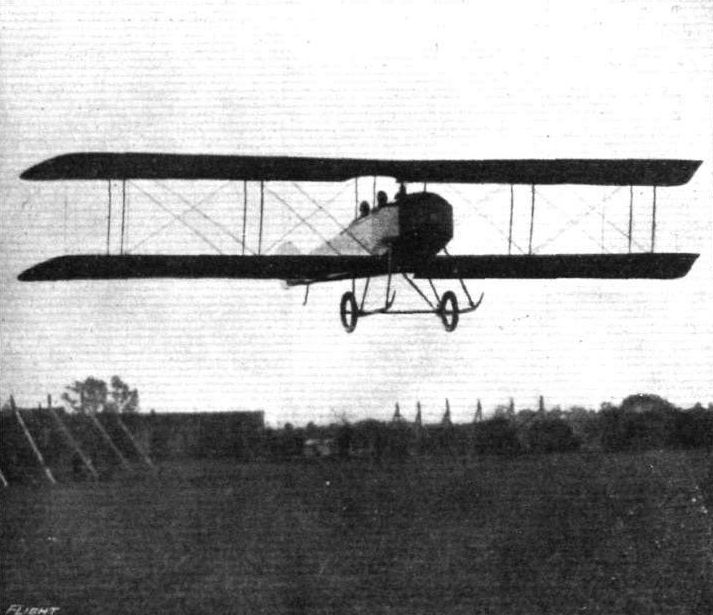
The 90 h.p. Mayo tractor biplane in flight.
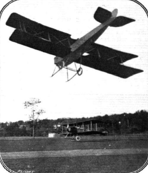
Two views of the 90 h.p. "Simplex" (Mavo) tractor biplane in flight. Below, just getting off with three passengers.
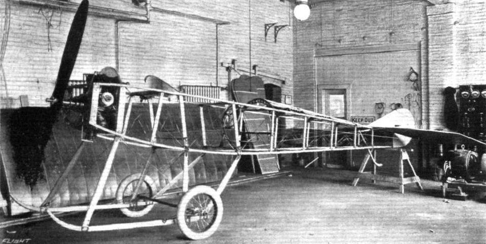
The partly assembled fuselage of the 90 h.p. "Simplex" (Mayo) tractor biplane. This view gives a good idea as to the substantial construction.
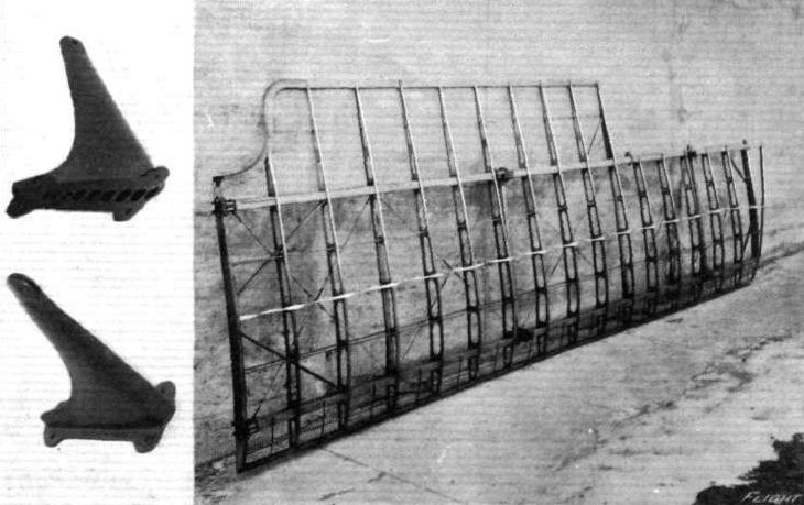
Constructional details of the 90 h.p. "Simplex" (Mayo) tractor biplane. - Left: Two control arms, as fitted to the elevators, ailerons and rudders. Right: The framework of one of the main planes. Note the cross struts for taking compression stresses.
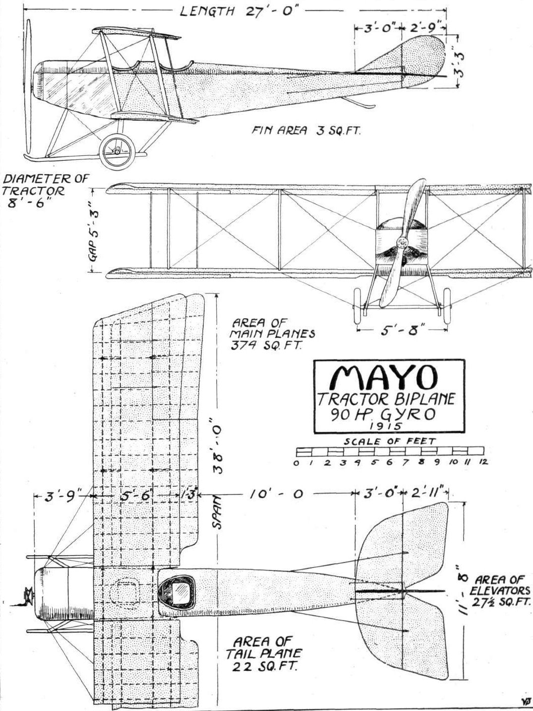
THE 90 H.P. MAY0 TRACTOR BIPLANE. - Plan, side and front elevation to scale.
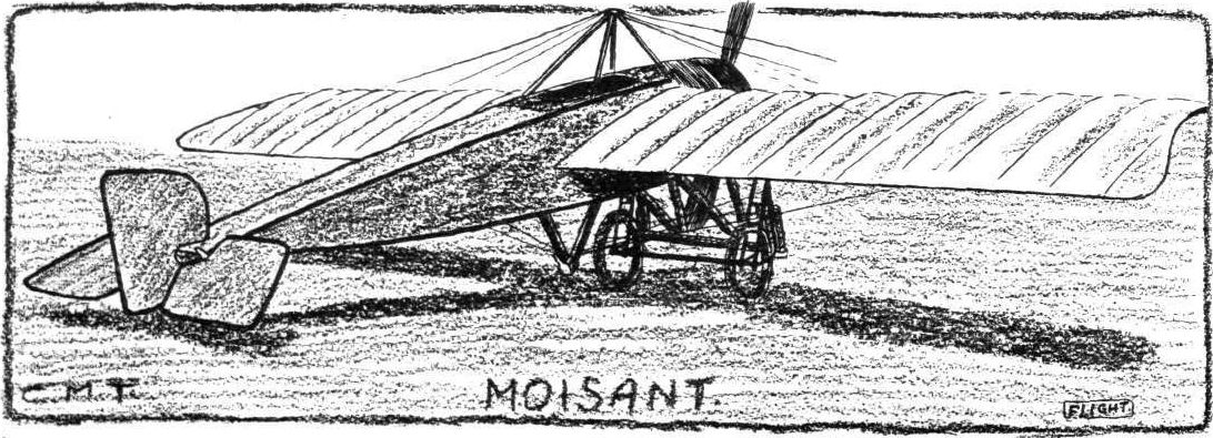
THE MOISANT TWO-SEATER MONOPLANE. - An interesting American machine, the general design of which, as regards the fuselage and planes, is similar to the Morane, while the under-carriage is of the Bleriot type, a combination which should prove extremely useful.
Flight, January 1, 1915.
THE 50 H.P. PARTRIDGE TRACTOR BIPLANE,
THIS machine is one of the several successful tractor biplanes manufactured by Messrs. Partridge and Keller, of the Cicero Flying Ground, at Chicago, Ill. In actual practice all have proved to be very steady flyers, several well-known American pilots, including Miss Katherine Stinson, having put up creditable performances on them. The machine shown in the sketch plan and elevation was built during the latter part of last year, bearing several modifications of the earlier models as the results of experience. The main planes are built up on two main spars of I-section ash measuring 2 1/4 ins. by 1 7/8 ins. front, and 2 1/4 ins. by 1 7/8 ins. rear respectively. The ribs consist of spruce battens and perforated webs. Between the front and rear spars, where the interplane struts are connected, are tapering compression members which relieve the ribs of any compression strains. Internal cross bracing is by 3/32-in. stranded cable. The wing section is a modified monoplane type, having a camber - on the under surface - of 3 ins. at a point 38 per cent, from the leading edge, and with a slight wash out at the tips. The normal angle of incidence is about 2°. The top plane consists of three sections, a small central panel the width of the fuselage, and two outer sections which are attached to the inner section, whilst the lower plane is in two sections, one mounted on either side of the fuselage. Each outer cellule has two pairs of silver spruce struts situated close together near the wing tips, and the central section is supported on the fuselage by two pairs of tubular steel struts. External bracing is by heavy stranded cable, and the strut attachments are of the quick-detachable type enabling the planes to be easily detached. The planes are covered with linen treated with Emaillite. H inged to the outer extremities of the rear spars of both top and bottom planes are ailerons measuring 7 ft. by 1 ft. 6 ins. Each top aileron is connected to that immediately below it by a spruce strut, and right and left hand pairs are interconnected, their operation being by means of Curtiss-type shoulder yoke. The tail consists of a triangular-shaped stabilising surface set at a slight negative angle mounted on the upper longerons of the fuselage. Hinged to the trailing edge of the stabilizing surface are two elevator flaps with a partially balanced vertical rudder in between, which is hinged to the last strut of the fuselage. The latter is of rectangular section built up of four ash longerons, with struts of silver spruce, except those in the engine section which are of ash.
The engine, a 50 h.p. 6-cyl. water-cooled Kirkham, is mounted in the nose of the fuselage, this portion being covered in with sheet aluminium. Behind the engine are the passenger's and pilot's seats, the former being in front, the fuselage being fabric covered as far as the rear or pilot's seat. Two radiators for cooling the engine are mounted one on either side of the fuselage between the engine and passenger. Sheet metal fittings are used in the engine section of the fuselage, and for the rest the usual U-bolts are employed, whilst the whole is strongly braced with cable. The landing chassis consists of two long ash skids connected to the lower longerons of the fuselage by three ash struts each, and a tubular steel axle carrying a pair of 20-inch wheels, which is attached to the skids by means of rubber shock absorbers. The skids extend forward of the 7 ft. 2 in. tractor screw, and are braced transversely by cable, no cross struts being employed.
The principal dimensions of this machine are: Span (top and bottom), 30 ft.; chord, 5 ft.; gap, 5 ft. 8 ins.; supporting area, 290 sq. ft.; area of stabilising plane, 14 sq. ft.; overall length, 24 ft. 1 in.; weight, empty, 730 lbs.; speed, 52 m.p.h.
"VEE JAY."
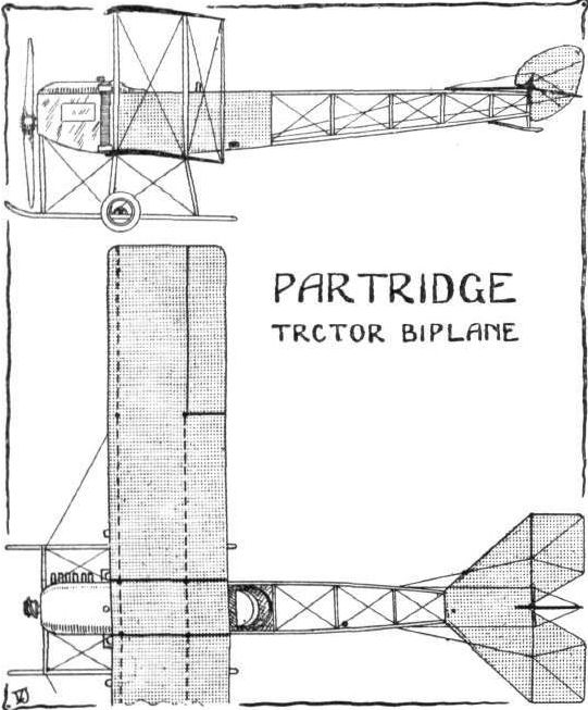

Miss Katherine Stinson at the wheel of her new tractor, in which she has been looping the loop at Chicago. Miss Stinson, it is claimed, is the first woman pilot to loop the loop.
Flight, January 29, 1915.
EDDIES.
It is quite surprising what a number of new interesting machines have made their debut in the U.S.A. during the last year or so, and in reviewing the ever-growing list of newcomers one cannot help noticing how the general trend of design seems to be in the direction of the fast tractor biplane. Sorting out mentally those that come to mind, a goodly number of the more recent ones are clearly influenced by German practice as regards their general lay-out. Several of them have the arrow type or back-swept wings, to which class belongs also the little biplane illustrated in the accompanying photograph. This machine was designed by Mr. Frank Pontkowsky and built by the Schaap-Sestak Aviation Co. of Chicago. It is fitted with a 50 h.p. Gnome engine, and is said to be a very fast and steady little machine to handle. Among the pilots who have flown it is, I believe, Earl S. Daugherty, who claims to have flown more different types of machines than any other American aviator.
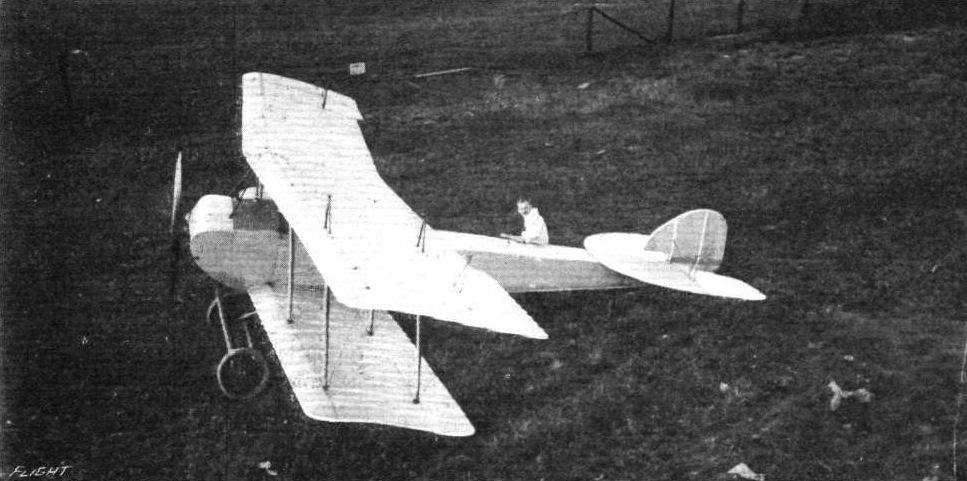
The 50 h.p. Pontkowsky tractor biplane built by the Schaap-Sestak Aviation Co. of Chicago, and flown by Earl S. Daugherty.
Flight, April 30, 1915.
THE MAXIMILIAN SCHMITT MONOPLANE.
IN the United States the monoplane has not been developed to anything like the same extent as the biplane. Indeed, what few monoplanes that have been manufactured have been mostly of the Bleriot type, and originality has only shown itself in one or two cases. One of these is to be found in the Maximilian Schmitt monoplane, which made its first appearance at Paterson, N.J., last summer, when F. C. Hild did much successful flying on it. As will be seen from the accompanying sketches, the construction of the body of this machine is unusual. The forward portion of it consists of a coque of true streamline form, circular in section, tapering at the rear into an after portion rectangular in section and very flat and narrow, which carries the tail planes. Thus the forward portion is of ample proportions for housing the pilot, fuel tanks, and engine. The latter, which is a 50 h.p. Gnome, is mounted in the nose with a metal cowl over the top that deflects the greater part of the exhaust and oil away from the pilot's cockpit. The landing chassis is similar in appearance to that fitted on the British-built Deperdussin monoplane, consisting of two U members built into the body. In the Deperdussin these members were of multi-ply wood, whereas those of the Schmitt are, we believe, of steel. The tubular axle carrying a pair of running wheels is attached to the lower ends of the U members by rubber bands, whilst radius rods hold the axle in correct alignment. Two cane skids attached to the body underneath the tail planes keep the latter clear from the ground. The main planes are built up on two main spars in the usual monoplane style in two units, being attached to the body high up. The rear spar is situated some distance from the trailing edge, so that a very effective warp is provided. A portion of the plane behind the rear spar on either side of and close to the body is cut away in order to provide an uninterrupted view below for the pilot. The wings are cable-braced top and bottom, in the former case from a pyramid of four steel tubes mounted on the body just in front of the pilot's cockpit and in the latter case from the U members of the landing chassis. The tail planes consist of a triangular stabilising plane, to the trailing edge of which are hinged two elevator flaps and two triangular vertical fins above and below the stabilising plane, with a vertical rudder hinged to the rear edge. The principal dimensions of the Maximilian Schmitt monoplane are Span, 25 ft.; chord, 6 ft.; supporting area, 150 sq. ft.; overall length, 18 ft.; weight in flying trim, 600 lbs.; speed, 65 m.p.h.; climbing speed, 50 ft. per min.
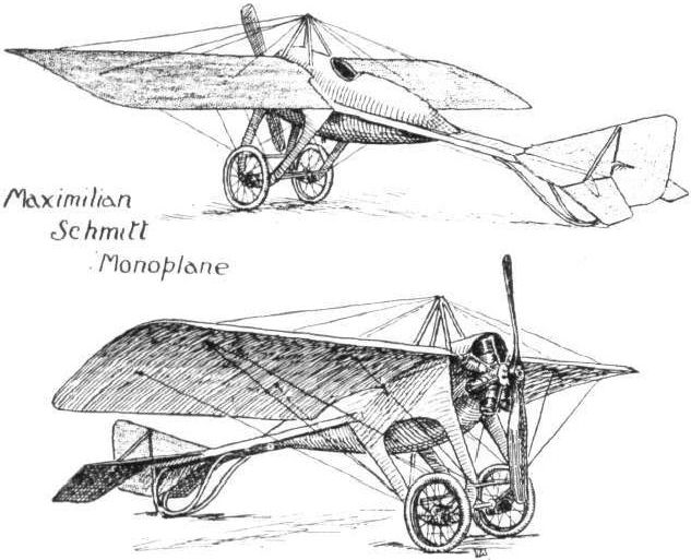
Maximilian Scmitt Monoplane.
Flight, December 17, 1915.
THE SHAW FLYING BOAT.
QUICK rising from the water, speed, and seaworthiness are the three primary considerations aimed at by the designer of the Shaw flying boat, and at the same time the comfort and protection of the pilot and passenger and the general stability of the machine in the air, have not been sacrificed to attain this end. From the accompanying scale drawings it will be seen that the Shaw flying boat is unique in several respects. The hull, for instance, is very short, and follows motor boat, or hydroplane, practice to a much greater extent than in most other flying boats. Another feature is that the engine is placed in the hull forward of the main planes and the pilot and passenger, and drives the propeller mounted at the rear of the planes through a shaft and chain. The tail, also, is unusually short with a slight angle of incidence, being so designed to facilitate the "get off," and to eliminate tail drag in so doing. Although it is typically a "sporting" 'bus, the Shaw flying boat is also adaptable to naval or military requirements, for, in addition to the foregoing features, provision is made for mounting a gun in front of the foremost cock-pit.
The main planes are of the double-surfaced laminated-rib type, having a chord of 5 ft. 6 ins., and a span of 42 ft. 4 ins. and 34 ft. 4 ins. top and bottom respectively. The front spar, which forms the leading edge, is built up of three laminations of spruce, ash and spruce, laid one on the top of the other as shown in Fig. a. The ribs are also laminated in a similar manner with five laminations, the central member being of ash and the others of spruce. All the ribs are spaced 1 ft. apart. The top plane is in three sections, a central panel 6 ft. span to which the outer sections are attached, while the lower plane is in two sections with open spaces of about 16 ins. width on either side of the boat.
Irish linen doped with Emaillite is used for covering the planes. Top and bottom planes are separated 5 ft. 6 ins. apart by six pairs or struts. These are of streamline section, measuring 3 ins. by 1 1/8 ins., and are built up of five laminations of spruce and ash, as shown in Fig. 3. They are attached to the planes by special quick detachable sockets made of malleable aluminium nickel plated. Two balancing flaps, 7 ft. 2 ins. by 2 ft. 8 ins., are hinged to the rear spar of the top plane, and are interconnected.
The tail is located only a short distance from the main planes, and consists of a horizontal triangular stabilizing surface with two elevators hinged thereto, a vertical triangular fin, and a partly balanced rudder hinged to the stern of the boat and the vertical fin. The horizontal surface, which is in two sections, is set at a slight lifting angle, and is strongly mounted above the stern of the boat by tubular supports. The fin is similarly supported underneath.
The propeller, an 8 feet diameter Shaw, is mounted high up behind the main planes by an arrangement of tubular struts. It is driven, by a single chain, off the shaft from the engine, a 90 h.p. Johnson two-stroke, which is mounted in the forward portion of the boat.
Measuring 20 ft. long, the boat is of the single step type, the bottom, from the step to the nose, being of V form and curving upwards. Aft of the step the boat also curves slightly upwards and tapers to a point. The hull is built up of two-ply mahogany and canvas, copper riveted, over a framework of ash longitudinals and spruce ribs (Fig. 4). It is divided into some six bulkheads, and the nose is neatly streamlined by a canvas hood at the extreme bows and by a sheet steel bonnet over the engine.
At the rear of the engine bonnet is the radiator, which is made to fit flush with the former. Behind the engine compartment are the passenger's and pilot's cockpits, each having a small cowl or dash in front as a protection from wind and spray. A Deperdussin type control is provided for both pilot and passengers.
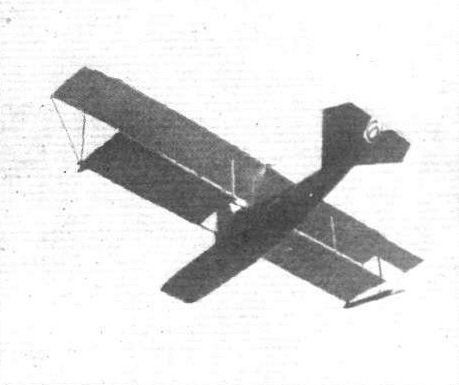
Fig. 1. - View of the first model Shaw flying boat in flight.
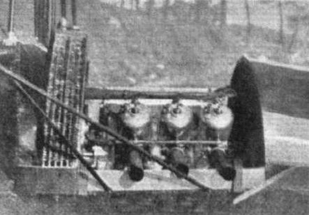
The 90 h.p. Johnson 2-stroke engine, in its cockpit, of the Shaw flying boat.
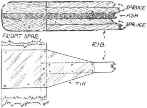
Fig. 2. - The Shaw Flying Boat. - The construction of the front spar and ribs.
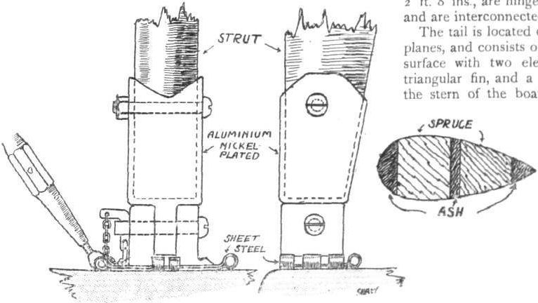
Fig. 3. - The Shaw Flying Boat - The interplane strut socket and section of strut.
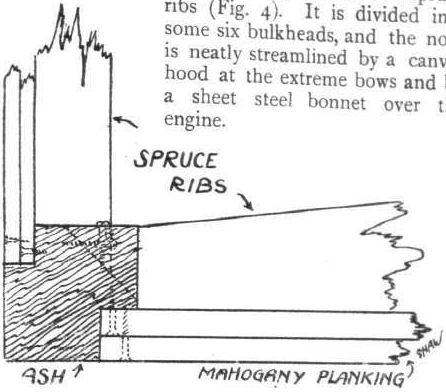
Fig. 4. - The Shaw Flying Boat. - Method of building up the hull.

THE SHAW FLYING BOAT. - Plan, side, and front elevation to scale.
Flight, May 21, 1915.
THE SLOANE TRACTOR BIPLANE.
ANOTHER American firm which has produced a tractor biplane on more or less standard lines for military purposes is the Aircraft Company, of New York, U.S.A., the manufacturers of the Sloane aeroplanes. The main planes, both in design and construction, are similar to those obtaining in monoplanes, and have the popular Morane-Saulnier plan form. The front spar, which measures 2 3/8 ins. by 1 3/8 ins., is situated some 10 ins. from the leading edge, whilst the rear spar is 1 ft. 8 ins. from the trailing edge, so that there is a fair amount of flexibility. Ash and spruce are employed in the building up of the frame, all joints being securely mortised. The frame is internally braced with heavy wire and covered with unbleached linen doped with Naiad aero varnish. The upper plane, which is staggered forward 10 ins., has an overall span of 36 ft. 6 ins., and overhangs the lower plane by 2 ft. on either side. Six pairs of stream-lined struts separate upper and lower planes, the two innermost pairs being mounted on the body. The lower plane is in two parts, and is attached to the lower longitudinals of the body. A pair of balancing flaps, each 10 ft. span, and of greater chord at the tips, where they are slightly upturned, are hinged to the rear spar of the upper plane only. The gap is 6 ft, and the supporting surface is 400 sq. ft. A divided elevator of the Morane-Saulnier type and a balanced rudder make up the tail.
The body is of rectangular section tapering to a horizontal knife-edge at the rear. It is built up of four ash longitudinals, 1 1/4 ins. square in front tapering to 1 in. square at the rear, and braced by eight sets of struts joined by clamps which have been specially designed to obviate any weakening of the longitudinals; it is further cross-braced with wire and wooden diagonals at points of greatest stress. At about mid-length the body is divided, at a point just behind the pilot's cockpit, which is immediately at the rear of the trailing edge of the upper plane. In front of the pilot's cockpit, is one for the passenger; at this portion of the body it measures 2 ft. 6 ins. by 2 ft. 11 ins., and is provided with a turtle deck. The whole of the body is fabric covered, and the nose, in which the engine is mounted, is almost totally enclosed by a round aluminium cowl, thus presenting a good streamline form. The engine is an 80 h.p. rotary Gyro, supported by special ball-bearing brackets.
The landing carriage is of the four-wheeled type, consisting of two skids connected to the body at their rear extremities, and by a vertical strut at each axle mounting. The larger pair of disc wheels are situated under the front spar of the lower plane, and the smaller pair come under the engine. Both axles are attached to the skids by rubber shock absorbers. We believe a modified chassis consisting of two pairs of V struts carrying a pair of disc wheels with axle, and a small wheel mounted well forward, will be fitted. The tail is supported by a "hockey-stick" ash skid sprung by means of rubber shock absorbers.
A Deperdussin type of control is fitted consisting of a wheel, operating the balancing flaps, mounted, on a column, a fore-and-aft movement of which actuates the elevators, and a foot bar operating the rudder. The control wires for the rudder and elevator are taken through the body. If required dual control can be fitted.
The speed range of this machine, which is known as type E-2, is said to be 40 to 70 m.p.h., whilst a climbing speed of 4,000 ft. in 10 mins., with full load, is guaranteed. It can also be readily adapted for use as a seaplane.
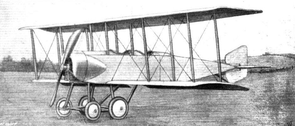
THE SLOANE TRACTOR BIPLANE. - Three-quarter view from the front.
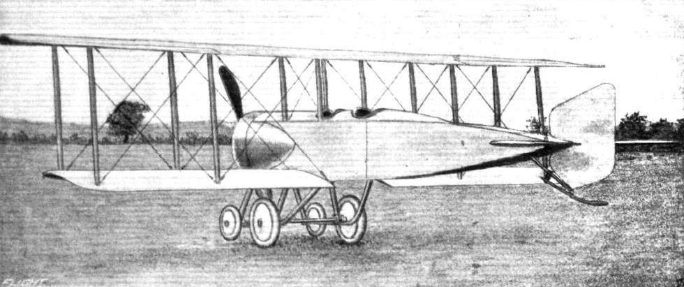
THE SLOANE TRACTOR BIPLANE. - Three-quarter view from behind.
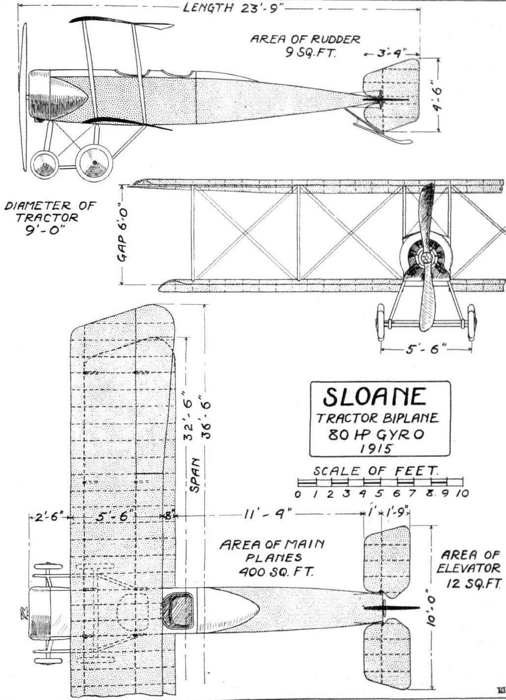
THE SLOANE TRACTOR BIPLANE. - Plan, side and front elevations to scale.
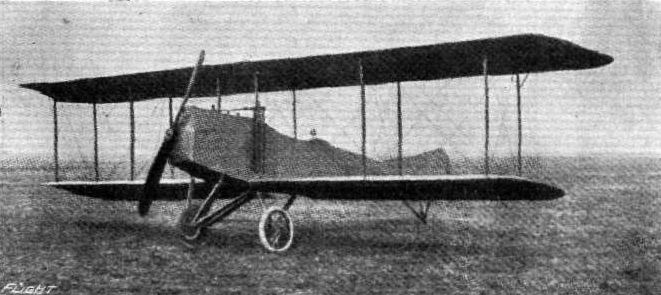
The latest Sloane Military Tractor Biplane. - This machine differs, apart from details, from that described in our issue for May 21st, in the three-wheel landing carriage, the vertical tail fin, and the fitting of a 90 h.p. water-cooled Kirkham engine.
Flight, June 4, 1915.
THE THOMAS FLYING BOAT.
(SPORTING TYPE.)
SOME little time ago we published a description and scale drawings of the Thomas military tractor biplane, which had done so well in its preliminary trials. A few particulars and the accompanying illustrations of a flying boat built by this same enterprising firm are now to hand. It should be stated at the outset that this flying boat is not by any means the first to be turned out by the Thomas factory, which is now situated at Ithaca, N.Y., on Lake Cayuga. As a matter of fact, Messrs. Thomas Brothers have had several years of experience in the construction of this type of craft.
In its general arrangement the Thomas flying boat does not represent any radical departure from usual practice, but when one comes to look into the construction several innovations are to be found. The main Planes, of which the upper one possesses a considerable overhang, are rectangular in plan form, and are separated by two pairs of vertical interplane struts on each side. The weight of the top plane extension is taken by two struts sloping outwards to a point near the tip, and attached at their lower ends to the bottom plane at the point where the outer pair of struts are secured. The engine - a 90 h.p. Austro-Daimler - is mounted on a structure of steel tubes slightly more than half-way up between the planes. It is started in the usual way by means of a starting handle projecting out in front and within easy reach of pilot or passenger. As is the usual practice in flying boat design, the propeller is placed at the rear of the planes. The trailing edge of the top plane has been cut away in the centre up to the rear spar to give clearance for the propeller. A small petrol service tank having the shape of a somewhat deeply cambered aerofoil is mounted on top of the upper plane, and petrol is fed to the carburettor from this tank by gravity. The main tank is placed down inside the boat, from which the fuel is fed to the service tank by means of a pressure pump.
One of the most interesting features of the machine is the construction of the boat, which, as regards shape, does not differ greatly from what may be termed standard practice. The framework of the boat is made of spruce, and over this is a planking of two thicknesses of cedar. Instead of the third wooden skin which is generally employed to complete the planking of the hull, the outer covering of the Thomas flying boat consists of light gauge sheet steel, which is claimed by the makers to ensure an absolutely leak-proof boat. It is to be presumed that this outer covering is well protected against the action of sea-water by some non-corrosive composition. Pilot and passenger are installed side by side in a very comfortable cockpit, the pilot occupying the seat on the left hand side. Control is by means of a rotatable hand-wheel mounted on a vertical column, and operating the elevator and rudder. The double-acting ailerons attached to the trailing edge of the upper plane are operated by means of a foot bar, but, if desired by the purchaser, the more generally adopted system of control, i.e., hand-wheel for ailerons and elevator and foot-bar for the rudder, can be substituted. The instruments include revolution counter, which can be engaged and disengaged at will, air speed indicator, clock, barograph and compass. A 10 lbs. folding anchor is also provided. Cylindrical metal floats fitted with spring boards are attached to the outer ends of the lower plane.
Mounted on a structure of steel tubes bolted to the rear portion of the boat is a fixed horizontal stabilizing plane to which is hinged the divided elevator. Below the stabilising plane is a small vertical fin, attached to the deck of the boat and to the rudder post. Round the latter is pivoted the partly balanced rudder.
The following general dimensions should give a good idea of the proportions of the machine: Length o.a., 25 ft. 5 ins.; span of top plane, 36 ft. 3 ins.; span of lower plane, 28 ft. 3 ins.; chord, 5 ft.; gap, 5 ft. 9 ins.; area, 325 sq. ft.; length of boat, 23 ft.; beam-top, 3 ft. 4 ins.; bottom, 2 ft. 10 ins.; maximum depth, 3 ft.; climbing speed, about 500 ft. per minute; horizontal speed, 68 m.p.h.
Flight, October 29, 1915.
THE 1916 THOMAS FLYING BOAT.-TYPE B.
IN the several years which have elapsed since the Thomas Brothers produced their first flying machine, every new type turned out, first at the Bath Works, N.Y., and more recently at the new extensive shops at Ithaca, N.Y., has incorporated some improvement suggested by the experience gained with the preceding machine. Their experience, too, has not been confined to a single type, but they have, as the pages of "FLIGHT" bear witness, produced both tractor and "pusher" land machines and flying boats. This week we are able to bring the series up to date with photographs and particulars of the latest Thomas flying boat, which was finished and tested a few weeks ago.
Considered purely as a type, the new Thomas flying boat does not show any radical changes from general practice in flying boat design, but great attention has been paid to the detail construction, and the finish, we are told, is of a very high quality.
In its general arrangement the 1916 model Thomas flying boat follows along the lines of its prototypes, having a boat-shaped hull in which accommodation is provided for pilot and passengers as well as for the main petrol tanks, while the engine is mounted comparatively high in the gap between the main planes. As the accompanying illustrations show, the upper main plane, which has a larger span than the lower, is straight, while the lower is set at a very pronounced dihedral angle.
The hull or boat is built up of a framework of ash covered with mahogany planking, and the bottom, which is slightly "Vee"-shaped in front, flattens out gradually towards the step. From there to the stern, the boat is flat bottomed. Slightly ahead of the wings and inside the hull are arranged the pilot's and passenger's seats, side by side, while a little farther back, between the spars of the lower planes in fact, is a second cockpit, with accommodation for additional passengers and extra petrol. All seats are upholstered with black leather and designed with a view to provide a maximum of comfort for the occupants.
In front of the pilot are the controls, which consist of a rotatable hand wheel mounted on a single pivoted column. A to-and-fro movement of the wheel operates the elevator, and rotation of the wheel works the rudder. The ailerons are connected up to two pedals fitted with stirrups to prevent any possibility of the feet slipping off. As in motor car practice, the throttle control of the engine is mounted on the steering wheel, and on a dash in front of the pilot is a neatly arranged set of instruments, including engine revolution counter air speed indicator (Pitot tube), altimeter, inclinometer hand-operated pressure pump, pressure gauge for the petrol, and a clock.
For purposes of transport the main planes are made up in six sections as follows :- Two upper plane extensions, two top planes, and two lower planes. They are built up of ribs over I-section spruce spars, the whole being covered with high-grade Irish linen, and "doped" with seven coats of Emaillite. In order to preserve the dope and to make the fabric absolutely water and moisture proof, a coat of varnish is finally applied, giving a highly glossy finish to the wing covering. Two pairs of streamline spruce struts on each side connect the main planes, cross bracing being effected by means of stranded cables manufactured by Roebling.
The tail planes are of the usual form. A vertical rudder is pivoted round an extension of the stern post of the boat, and to balance the side area in front, presented by the flat sides of the hull, a large vertical fin is fitted, running forward from the rudder post to a point slightly more than half way between the stern and the rear cockpit. The horizontal stabilising plane is of semicircular plan form, and is carried on stanchions running up from the deck of the rear part of the hull. To this stabiliser is hinged a divided elevator, operated in the usual manner through cables running from the control lever to short crank levers on the elevator.
At present the engine fitted is a 90 h.p. Austro-Daimler, which is supported on two engine bearers of ash, resting on four streamline ash struts that are secured at their lower extremities to the gunwales of the hull. In order to provide the necessary rigidity, and to take the stresses set up by the momentum of the engine when alighting two spruce struts are placed diagonally, running from the rear of the engine beaters to a point on the gunwales slightly ahead of the place where are attached the main front engine struts.
Great attention has, as we have already pointed out, been paid to the general finish of this machine. All internal wooden parts are treated with a waterproofing solution, while external parts of wood, such as struts and hull, are finished in natural wood. All metal parts are made rust proof by painting them with an anti-corrosive composition.
The chief characteristics of the new Thomas flying boat are: Span of top plane, 39 ft.; span of lower plane, 28 ft.; chord, 5 ft.; gap, 6 ft.; over all length, 28 ft. 6 ins.; area, 360 sq. ft.; loading, 4.3 lbs. per sq. ft.; weight empty, 1,250 lbs.; speed, 65 to 70 m.p.h.
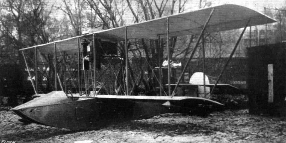
Three-quarter front view of the Thomas flying boat.
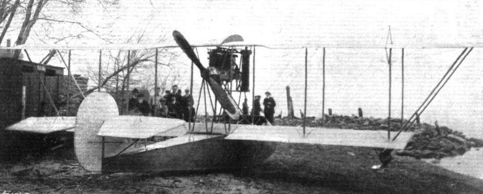
Three-quarter rear view of the Thomas flying boat.

The Thomas flying boat over Lake Cayuga. - The pilot is holding his hands above his head to show the stability of the machine.

Front view of the new Thomas flying boat.
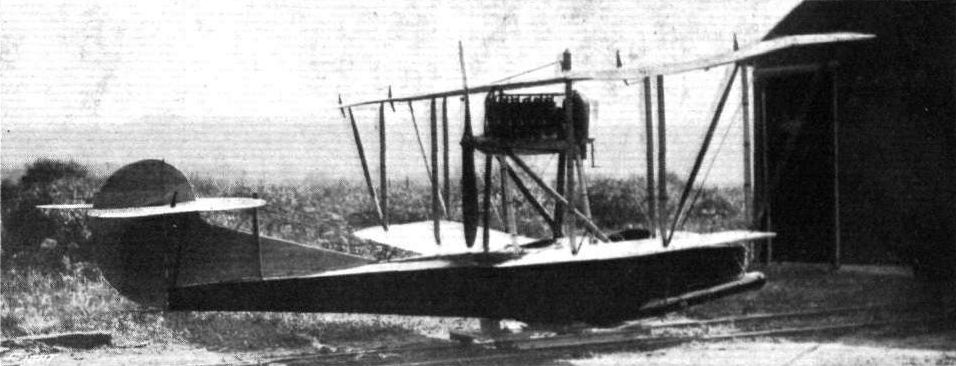
Three-quarter rear view of the new Thomas flying boat.
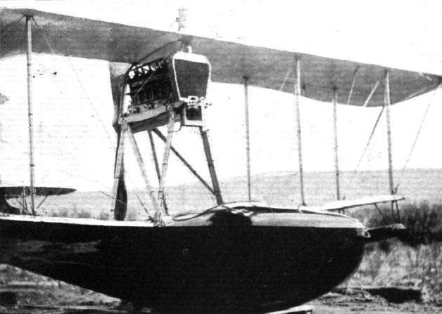
Front portion of the hull and engine mounting on the new Thomas flying boat.
Flight, April 23, 1915.
THE THOMAS MILITARY BIPLANE.
ONE of the several new American machines which have recently been produced, is the tractor biplane, shown in the accompanying illustrations, designed and constructed by Messrs. Thomas Brothers, of Ithaca, N.Y., with a view to meeting the requirements of the U.S. military authorities. Nothing very startling is claimed for this new biplane by its designers, but it is a sound serviceable machine, built on what might be termed standard lines, and incorporating in its construction many novel features. Briefly the Thomas military tractor is a two-seater biplane with a fuselage of good streamline form, and fitted with a stationary engine - in the case of the test machines we believe the engine was a 90 h.p. Austro-Daimler. The over-all length is 26 ft., the span 36 ft., chord 5 ft., gap 5 ft.; weight, empty, 1,075 lbs.
During the test flights the following results were obtained:-
U.S. Army Requirements. Result of Tests.
Speed 70 m.p.h. 81.1 m.p.h.
Useful load 750 lbs. 800 lbs.
Climb fully 4,000 ft. in 10 mins. 1800 ft. in first min.
loaded 14,000 ft. in 10 mins.
Slow speed 40 m.p.h. 38m.p.h.
Propeller efficiency 70 per cent. 75 per cent.
The full load consisted of pilot, two passengers, and four hours' fuel.
As regards constructional details, the fuselage, which is of rectangular section in front, gradually tapering to a section, having its sides sloping inwards, counting from top to bottom, is built up of ash longerons connected with spruce struts. Both longerons and struts are lightened by being milled out to an I section, and are connected by means of steel plates bolted to the longerons in such a manner that the bolts pass through the neutral axis of these members.
In the extreme nose of the fuselage is the engine, mounted on two very stout ash bearers, which are in turn carried on two transverse members of the fuselage. Immediately in front of the engine is mounted the radiator, which is provided with an opening through which passes the propeller shaft. Behind the engine is a transverse panel, to which is secured the petrol service tank, whence fuel is fed to the engine by gravity. A larger tank containing 20 gallons of petrol rests on the lower longerons, and above this main tank is placed the observer's seat. As the fuel in the service tank is consumed, it is replenished from the main tank by means of a hand-operated pump placed in the pilot's cockpit.
To the rear of the observer's seat is a second transverse panel, which serves as an instrument board, with the following instruments let in, so that the dials are flush with the board: Petrol pressure gauge. "Tel" revolution indicator, inclinometer, clock, barograph, air speed indicator, switch, petrol cut-off cock and spark advance lever. The controls in front of the pilot are of the wheel and column type, the wheel operating the rudder, whilst a to-and-fro movement actuates the elevator. Lateral control is at present effected by means of a shoulder yoke operating through flexible cables the double acting ailerons, but if desired a more orthodox form of lateral control can be substituted. A turtle back, formed in front by the aluminium bonnet over the engine and in the rear by stringers covered by fabric, tops the fuselage, which is also provided with a curved "belly" formed in the same manner as the turtle back.
In front the fuselage is enclosed in a covering of light gauge sheet metal, whilst the rear part is covered in the usual way with fabric.
The tail planes, which are built up entirely of steel tubing, consist of the usual members, i.e., a flat, non-lifting stabilising plane - to which the elevator is hinged - and of a partly balanced rudder. A small skid mounted on a continuation of the rudder post protects the tail planes against contact with the ground.
A chassis of the wheel and skid type takes the weight of the machine when on the ground. The two ash skids are carried on six chassis struts of the same wood coming down from the lower longerons of the fuselage. The first pair of these struts are attached to the fuselage approximately under the centre of the engine, and the second pair run to the point where the rear engine bearer is secured to the fuselage. The rear pair of struts are attached to the fuselage longitudinals at the point where these meet the rear spars of the lower main plane. The stub axles are secured at their inner ends by a pin passing through the two transverse chassis members connecting the skids and between which the axles work. Rubber shock absorbers passing round the axles and secured to the skids provide the necessary springing. Cross wiring of the chassis is effected by stranded cables of ample proportions. The two disc wheels are of 26 ins. diameter, and fitted with 4 in. tyres.
In plan view the main planes are of a form that is rapidly becoming popular with a number of aeroplane designers both in this and other countries, that is to say having their trailing edge slightly longer than the leading edge, a form which is generally considered to minimize end losses. Both upper and lower planes are built in right and left hand pairs, the two halves of the upper plane being attached to a centre section mounted on four short struts coming from the upper longitudinals of the body. In order to give a better view in an upward direction, the trailing edge of this centre section has been cut away.
The wings are built up of silver spruce spars, milled out to an I section, except where are attached the interplane struts. The ribs are also of I section, having thin spruce webs and being fitted with flanges. At the point of attachment of the interplane struts the ribs are of the box type.
All the internal wood-work is painted with a water-proof preparation. The various bays in the wings are internally cross braced with solid steel wire. It is stated by the designers that the factor of safety is nowhere less than 7, which figure is exceeded in many places. Double acting ailerons are hinged to both upper and lower planes, so that there should be ample lateral control. In order to render the ailerons still more effective, their trailing edge projects some little distance behind that of the main planes.
Special attention has been given to demountability and accessibility of all important parts. Such fittings as wing stay fastenings and strut connections can be very quickly assembled and again taken down.
At their new works at Ithaca, N.Y., to which locality they moved some little time ago, Messrs. Thomas Brothers have facilities for turning out machines at a rate to satisfy Government demands, and on Lake Cayuga a 40-miles stretch of water is available for testing waterplanes, of which this firm have produced several types, while adjoining the lake is a good size aerodrome, where the land machines are put through their trials.
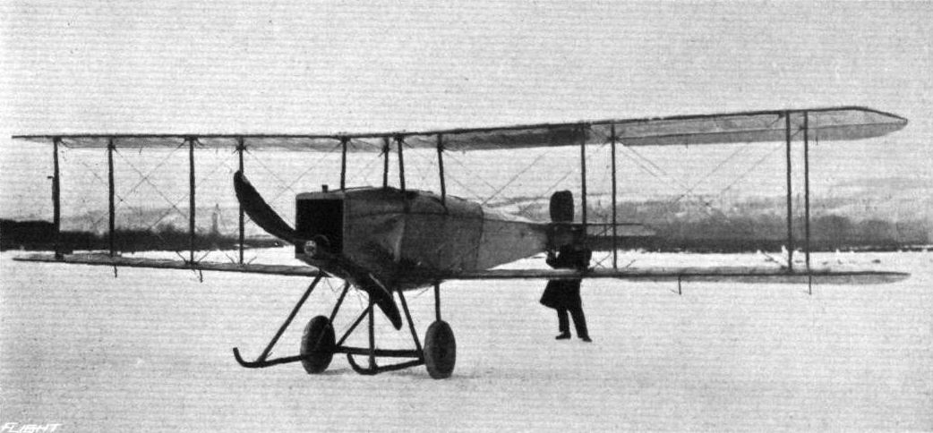
Three-quarter view from the front of the Thomas military tractor biplane.
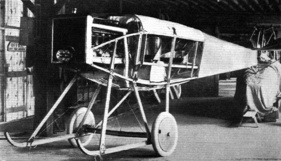
View of the fuselage of the Thomas military tractor biplane, showing engine mounting, seating arrangement, and chassis.
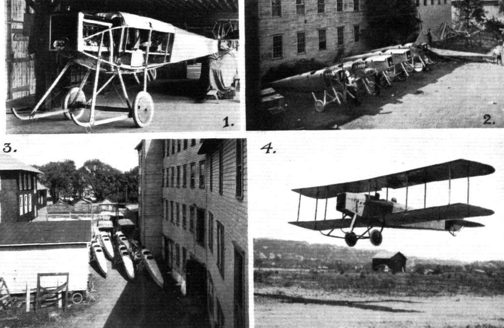
FROM THE ITHACA WORKS OF THOMAS BROTHERS AEROPLANE CO. - 1. Fuselage of a Thomas military tractor. 2. A batch of Thomas fuselages ready for the wings. 3. Fuselages ready for shipment. 4. Thomas military tractor going through preliminary tests at the Ithaca flying ground.

One of the latest Thomas military biplanes, with 90 h.p. Curtiss engine, just off for a trial spin at Ithaca. Incidentally, this view gives an idea of the splendid facilities possessed by the Thomas Brothers at Ithaca. They have two large aerodromes beside Lake Cayuga, one being reserved for testing new machines and the other for the flying school, while for flying-boat work, Lake Cayuga, which is 40 miles long and four miles wide, is available. The hills seen in the distance are at the other side of the lake.
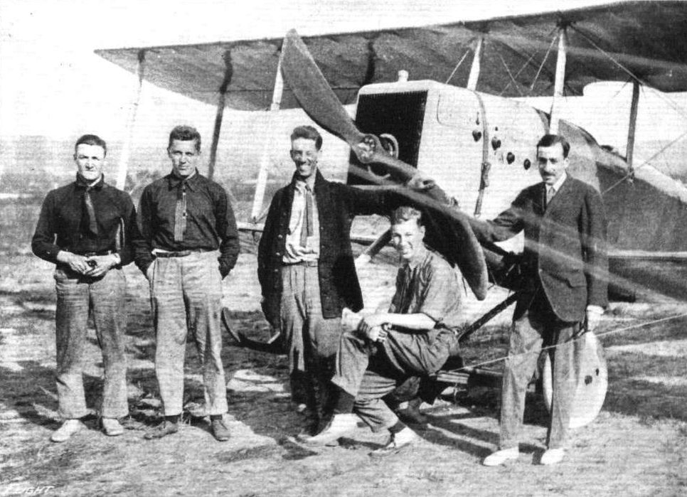
CANADIANS LEARN TO FLY IN THE UNITED STATES. - So many Canadians are desirous of learning to operate aeroplanes for war service that the aviation schools in Canada cannot accommodate all of them. Many are being instructed in the United States. The above group, photographed in front of a Thomas warplane at Ithaca, N.Y., includes (left to right) Frank McGill, 100-yard and 1-mile Canadian swimming champion; George Hodgson, 100-yard Olympic swimming champion; Frank Burn side, the instructor in aviation at the Thomas School; Phillip Fisher and Hugh Peck.
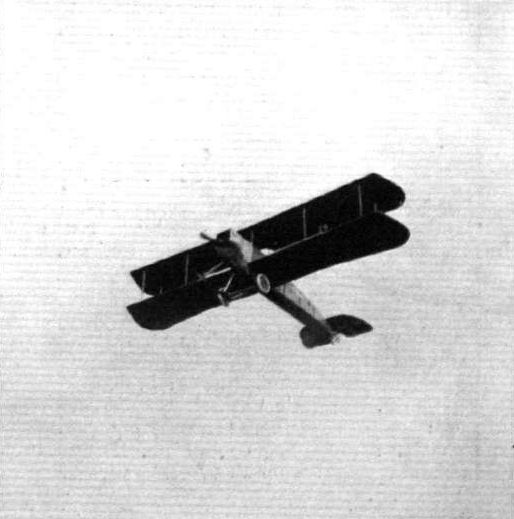
The Thomas military tractor in flight.

THE THOMAS MILITARY BIPLANE. - Plan, side and front elevation.
Flight, February 19, 1915.
EDDIES.
A new Wright biplane of somewhat different design from the usual type has been completed recently at the Beatty school at Hendon. The new machine, which is fitted with a 50 h.p. Gnome, is intended for the use of pupils when making their test flights for their certificate. Those who have been fortunate enough to have a spin on her agree that she handles very nicely and wants very little attention, except in very rough weather. The chief departure from standard Wright practice is to be found in the arrangement of the struts and spars. Instead of joining the front row of struts to the leading edge of the main planes, they are joined to a front spar placed some distance behind the leading edge. In other respects the new brevet biplane follows standard Wright practice.

Miss Katherine Stinson on an exhibition flight on her Wright biplane in America.
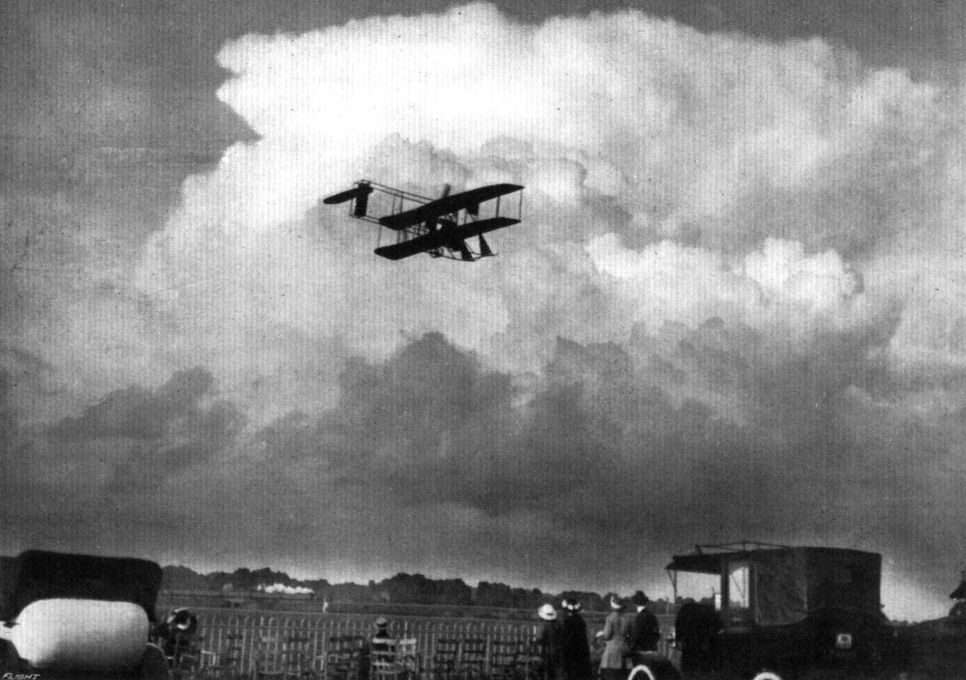
Stormy air-work by Mr. Roche-Kelly on a Beatty-Wright at Hendon.
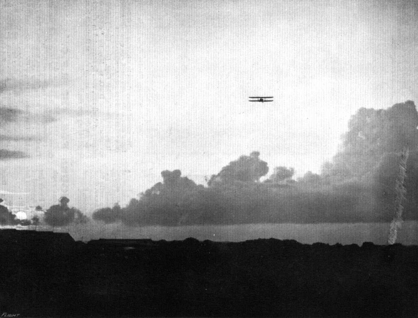
LATE EVENING AT HENDON. A SUNSET AND CLOUD STUDY. - Mr. C B. Prodger on a Beatty Wright machine.
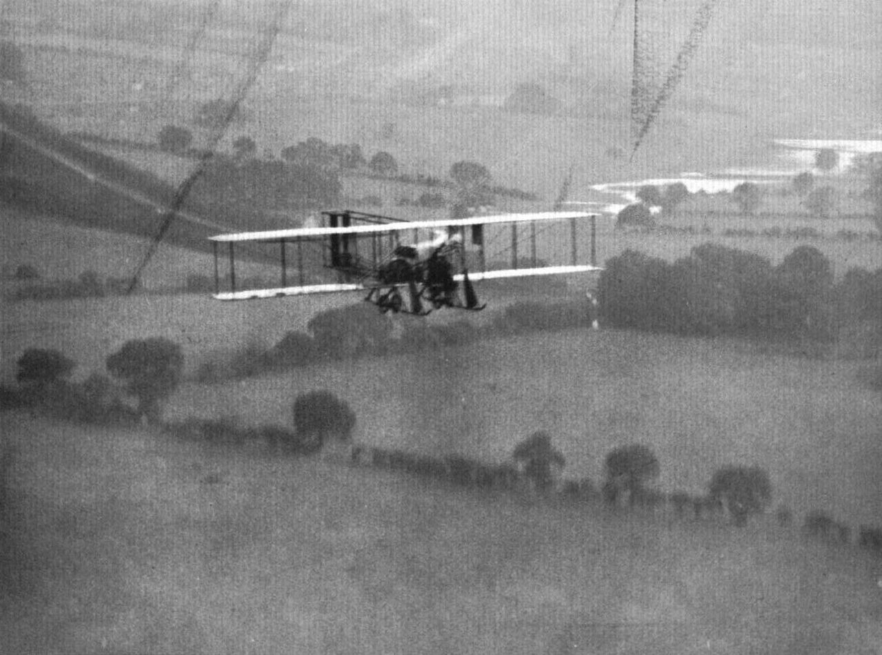
"FLYING AT HENDON," AS SEEN FROM ABOVE. - Mr. Roche-Kelly on the Beatty-Wright, taken from Mr. Prodger's Beatty-Wright.
CIRCLING AT HENDON. - Mr. Marcos D. Manton in the G.-W. Scout. In the distance one of the Beatty-Wright.
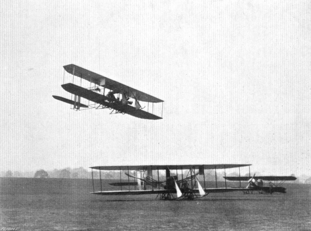
AT THE BEATTY SCHOOL, HENDON. - Mr. Roche-Kelly on a Beatty-Wright "jumping" over a similar machine on the ground.
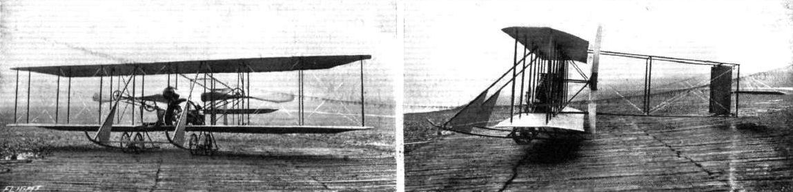
Two views of the new Beatty Wright biplane, which is now becoming very popular as a brevet machine.
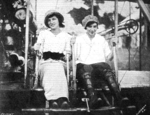
Misses Marjorie C. and Katherine Stinson, two American pilots. The former is aged 18, the latter 20, and both fly Wright machines. Miss Katherine Stinson has been flying for a long time past, her sister joining her last year, and they are continually giving demonstrations in the United States.
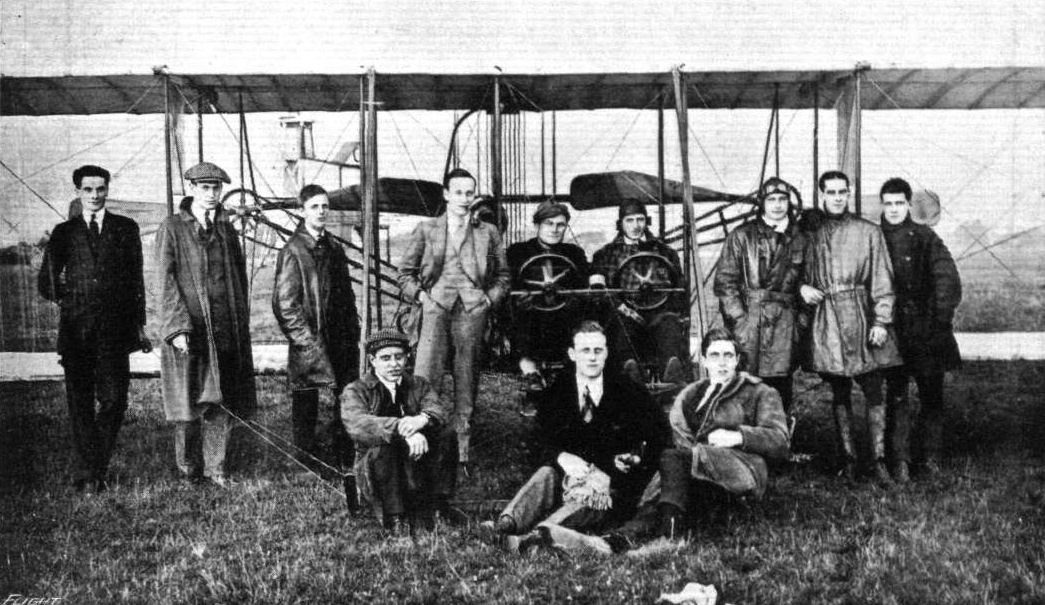
A batch of pupils and instructors (60 h.p. Wright) at the Beatty School, Hendon. - From left to right: (back row) Messrs. Fox, Hoskier, Crossman, Eaton, Lieut. Ross, Prodger (instructor), Arbon, Theo and Delves; (front row) Messrs. Jones, Kenworthy (Instructor) and King.

THE COUNTRY, AS SEEN FROM AN AEROPLANE. - View of Mill Hill, at an altitude of 1,000 ft. from a 50 h.p. Gnome-engined Wright biplane. From a sketch actually made during the flight by the artist, Mr. Roderic Hill. Below can be seen the town of Mill Hill and the Midland Railway curving away into the distance. Mr. Roche-Kelly, the very popular exponent of the graceful Wright machine, was Mr. Roderic Hill's pilot.
Flight, October 29, 1915.
CONSTRUCTIONAL DETAILS.-VIII.
<...>
In the sketches of the undercarriage of the Bathiat-Sanchez biplane is illustrated another method. Here the stub axles, which are universally pivoted to the central skid, are sprung by telescopic tubes both of which carry cross-pieces, to which are attached the rubber shock absorbers. The cross-piece of the inner tube works in a slot in the outer tube, the action being easily understood from an examination of the sketch. A refinement worth noticing in this undercarriage are the wheel brakes illustrated in the detail sketch. By means of these brakes, which are operated from the pilot's seat, the machine can be held back while running the engine, so that it is possible, by the aid of the brakes and the starting handle with which the motor is fitted, to start the machine without any outside assistance.
<...>
Various types of single-skid undercarriages.
Flight, November 12, 1915.
CONSTRUCTIONAL DETAILS.-X.
<...>
The last undercarriage shown on our page of illustrations this week, the Bathiat-Sanchez, does not perhaps strictly speaking constitute a "Vee" type, since the lower ends of its struts are not joined together directly. The short steel tube that supports the shock absorbers could hardly be called skids, however, and the chassis has therefore been included among the "Vee" types. The method of attaching the shock absorbers as well as the anchorage of the lift-cables will be easily understood from the sketches. The warp cables, this machine being a monoplane, are attached to a three-corned pyramid formed by three steel tubes and not being, of course, part of the undercarriage itself.
Various "Vee"-type undercarriages constructed of wood.
Flight, June 25, 1915.
EDDIES.
ALTHOUGH little has been heard of his doings lately, Mr. S. Summerfield, the well-known Bleriot pilot of Melton Mowbray, has by no means been idle during the past few months. Mainly he has been engaged testing various monoplanes of original design. Another development as the result of Mr. Summerfield's energetic efforts which is now approaching completion is the formation of a flying school in the Midlands. The location decided upon is Billesley Common, where several hangars are in the course of erection, and it is expected that the first of these will be ready for occupation by the beginning of next month. By way of a start three Bleriot monoplanes have been acquired, a choice that is natural enough when it is remembered that Mr. Summerfield has done most of his flying, or at any rate his best flying, on machines of this make. For instruction purposes the Bleriot is a particularly suitable mount, owing chiefly to the excellent chassis which allows a pupil to come down with a considerable side drift without the resulting "cart-wheel" that usually follows a landing of this description on a machine the wheels of which are not free to move sideways as they are on a Bleriot. In the higher-powered types also the Bleriot is sufficiently fast to make the change to the machines used by the authorities a comparatively easy matter for a pupil who has obtained his "ticket." Three models have, as already mentioned, been purchased, a 25 h.p., a 50 h.p. and a two-seater (presumably a 70 or 80 h.p. machine). In the course of a few weeks a couple of biplanes will be added housed in the hangars, a 45 h.p. and a 60 h.p. two-seater. Already several pupils have been enrolled so that it looks as if the new school is going to be right there from the very beginning. It only now remains for reports to come along of the actual air work. There is undoubtedly an excellent opening for good tuition in the Midlands, and under the management of Mr. Summerfield the new establishment should, to use a well-worn phrase, "fill a long-felt want." Good luck to the new combination.
Flight, September 24, 1915.
EDDIES.
It would be a difficult matter to forget the name of Lieut. Tryggve Gran, of the Norwegian R.F.C., who got his "ticket" at the Hall school, and who on July 30th of last year made his magnificent flight of some 320 miles across the North Sea, from Cruden Bay in Scotland to Klep on the Norwegian coast. After this fine achievement Lieut. Gran sold the Bleriot monoplane on which the flight was made to the Norwegian Government. Since the outbreak of war Lieut. Gran has been kept busy patrolling the Norwegian coast on a Bleriot two-seater, and chasing off submarines that seek refuge in the deep sheltered Fjords on the west coast, as recorded in "Eddies" several months ago. Lieut. Gran has now sent us some particularly interesting photos which show that he is now stationed far up north; in fact he claims that his station is the farthest north flying station in the world. That flying under the conditions existing up there is far from being a Sunday school picnic will be readily realised when it is remembered that the Norwegian coast is extremely rugged, and landing grounds few and far between. On the 7th of this month, Lieut. Gran made a 100-mile flight over the mountains at an altitude of about 5,000 ft. As this and others of his air journeys have taken place to the north of the Arctic circle, Lieut. Gran can claim, I should say, to be the first
Flight, November 5, 1915.
EDDIES.
In spite of the busy-ness of Hendon and the many more or less "near things" that occur almost daily up there, there is no case on record of a machine landing on top of another without, practically, any damage being done to either. The incident illustrated in our photographs occurred at a French aerodrome some little time ago. The machines were both landing, and the Voisin, piloted by an N.C.O. and having a pupil as passenger, was gliding along about six feet from the ground. The Bleriot was also coming down, and the fuselage and wings of the monoplane prevented the pilot from seeing the Voisin. At the instant when the biplane touched the ground the wheels of the Bleriot alighted on its upper plane, and so gentle was the impact that the pilot of the Voisin did not immediately realise that anything unusual had happened. All the repairs that were necessary when the machines had been parted were a new wheel for the Bleriot and a couple of ribs for the top plane of the Voisin.
Flight, November 19, 1915.
CONSTRUCTIONAL DETAILS.-XI.
IN our previous series of undercarriages an attempt was made to classify these, as far as possible, in order to facilitate reference. The three headings under which they were arranged, it may be remembered, were double skid, single skid, no skid types. Having dealt with a number of examples of each type there still remain several very interesting and highly successful makes of undercarriage which are well worthy of notice, but which, owing to their characteristics, cannot be classified under any of the above headings. These form the subjects for our full page of illustrations this week.
Having stood the test of time and being, perhaps, one of the most ingenious undercarriages ever designed, the Bleriot chassis will be dealt with first. The chief characteristic of this chassis is that it is fitted with castor wheels that are free to travel, not only upwards, but outwards to either side as well. The upward movement is obtained on the principle of the deformable triangle. Supported on two transverse members made of ash and secured to the fore part of the body are two vertical steel tubes of large diameter. Round the upper part of each of these tubes a collar is free to slide. Attached to this collar with their upper ends are two flattened steel tubes that form a fork round the running wheels which are secured to its lower end. Another fork that forms the third side of the deformable triangle to which reference is made above, runs from the lower end of the vertical tubes to the wheel. An inspection of the accompanying illustration should make the action clear. When the wheel moves upwards, its hub describing a portion of the arc of a circle, having for its centre the lower end of the vertical tube and having the lower, short fork as its radius, the movement is transmitted by the long forks to the sliding collar. The upward motion of this collar along the vertical tube is resisted by the rope-shaped shock absorbers seen in the sketch. These shock absorbers, of which there are two or four to each wheel according to their strength, have their ends fitted into metal caps from which strong steel wires are taken to the lower transverse member and to notched lugs on the sliding collars respectively.
The lower transverse member, or planche as it is sometimes called, is supported from the fuselage by six streamline wood struts, two of which are vertical whilst two slope forward to the nose of the body and two backward to the lower longitudinals. As the load is taken on the outer ends of the transverse members, these are strengthened by diagonal bracing, which, in the older machines, usually took the form of a steel band or tape; but which is now sometimes made of two stranded steel cables.
When landing with a slight sideways movement in relation to the ground the wheel, it will be seen, can move sideways by pivoting round the vertical tubes. This movement, however, is restricted by connecting the two wheel centres by a thin horizontal strut pivoted to the inner ends of the hubs and by diagonal cross wiring in which is incorporated elastic bands. The function of these bands, apart from restricting the lateral movement of the wheels, is to return the wheels to a central position. Although suffering somewhat from excessive head resistance, the Bleriot undercarriage has much to recommend it on account of its extreme flexibility, which allows of making landings that are far from perfection without serious consequences to the machine.
<...>
EDDIES.
ALTHOUGH little has been heard of his doings lately, Mr. S. Summerfield, the well-known Bleriot pilot of Melton Mowbray, has by no means been idle during the past few months. Mainly he has been engaged testing various monoplanes of original design. Another development as the result of Mr. Summerfield's energetic efforts which is now approaching completion is the formation of a flying school in the Midlands. The location decided upon is Billesley Common, where several hangars are in the course of erection, and it is expected that the first of these will be ready for occupation by the beginning of next month. By way of a start three Bleriot monoplanes have been acquired, a choice that is natural enough when it is remembered that Mr. Summerfield has done most of his flying, or at any rate his best flying, on machines of this make. For instruction purposes the Bleriot is a particularly suitable mount, owing chiefly to the excellent chassis which allows a pupil to come down with a considerable side drift without the resulting "cart-wheel" that usually follows a landing of this description on a machine the wheels of which are not free to move sideways as they are on a Bleriot. In the higher-powered types also the Bleriot is sufficiently fast to make the change to the machines used by the authorities a comparatively easy matter for a pupil who has obtained his "ticket." Three models have, as already mentioned, been purchased, a 25 h.p., a 50 h.p. and a two-seater (presumably a 70 or 80 h.p. machine). In the course of a few weeks a couple of biplanes will be added housed in the hangars, a 45 h.p. and a 60 h.p. two-seater. Already several pupils have been enrolled so that it looks as if the new school is going to be right there from the very beginning. It only now remains for reports to come along of the actual air work. There is undoubtedly an excellent opening for good tuition in the Midlands, and under the management of Mr. Summerfield the new establishment should, to use a well-worn phrase, "fill a long-felt want." Good luck to the new combination.
Flight, September 24, 1915.
EDDIES.
It would be a difficult matter to forget the name of Lieut. Tryggve Gran, of the Norwegian R.F.C., who got his "ticket" at the Hall school, and who on July 30th of last year made his magnificent flight of some 320 miles across the North Sea, from Cruden Bay in Scotland to Klep on the Norwegian coast. After this fine achievement Lieut. Gran sold the Bleriot monoplane on which the flight was made to the Norwegian Government. Since the outbreak of war Lieut. Gran has been kept busy patrolling the Norwegian coast on a Bleriot two-seater, and chasing off submarines that seek refuge in the deep sheltered Fjords on the west coast, as recorded in "Eddies" several months ago. Lieut. Gran has now sent us some particularly interesting photos which show that he is now stationed far up north; in fact he claims that his station is the farthest north flying station in the world. That flying under the conditions existing up there is far from being a Sunday school picnic will be readily realised when it is remembered that the Norwegian coast is extremely rugged, and landing grounds few and far between. On the 7th of this month, Lieut. Gran made a 100-mile flight over the mountains at an altitude of about 5,000 ft. As this and others of his air journeys have taken place to the north of the Arctic circle, Lieut. Gran can claim, I should say, to be the first
Flight, November 5, 1915.
EDDIES.
In spite of the busy-ness of Hendon and the many more or less "near things" that occur almost daily up there, there is no case on record of a machine landing on top of another without, practically, any damage being done to either. The incident illustrated in our photographs occurred at a French aerodrome some little time ago. The machines were both landing, and the Voisin, piloted by an N.C.O. and having a pupil as passenger, was gliding along about six feet from the ground. The Bleriot was also coming down, and the fuselage and wings of the monoplane prevented the pilot from seeing the Voisin. At the instant when the biplane touched the ground the wheels of the Bleriot alighted on its upper plane, and so gentle was the impact that the pilot of the Voisin did not immediately realise that anything unusual had happened. All the repairs that were necessary when the machines had been parted were a new wheel for the Bleriot and a couple of ribs for the top plane of the Voisin.
Flight, November 19, 1915.
CONSTRUCTIONAL DETAILS.-XI.
IN our previous series of undercarriages an attempt was made to classify these, as far as possible, in order to facilitate reference. The three headings under which they were arranged, it may be remembered, were double skid, single skid, no skid types. Having dealt with a number of examples of each type there still remain several very interesting and highly successful makes of undercarriage which are well worthy of notice, but which, owing to their characteristics, cannot be classified under any of the above headings. These form the subjects for our full page of illustrations this week.
Having stood the test of time and being, perhaps, one of the most ingenious undercarriages ever designed, the Bleriot chassis will be dealt with first. The chief characteristic of this chassis is that it is fitted with castor wheels that are free to travel, not only upwards, but outwards to either side as well. The upward movement is obtained on the principle of the deformable triangle. Supported on two transverse members made of ash and secured to the fore part of the body are two vertical steel tubes of large diameter. Round the upper part of each of these tubes a collar is free to slide. Attached to this collar with their upper ends are two flattened steel tubes that form a fork round the running wheels which are secured to its lower end. Another fork that forms the third side of the deformable triangle to which reference is made above, runs from the lower end of the vertical tubes to the wheel. An inspection of the accompanying illustration should make the action clear. When the wheel moves upwards, its hub describing a portion of the arc of a circle, having for its centre the lower end of the vertical tube and having the lower, short fork as its radius, the movement is transmitted by the long forks to the sliding collar. The upward motion of this collar along the vertical tube is resisted by the rope-shaped shock absorbers seen in the sketch. These shock absorbers, of which there are two or four to each wheel according to their strength, have their ends fitted into metal caps from which strong steel wires are taken to the lower transverse member and to notched lugs on the sliding collars respectively.
The lower transverse member, or planche as it is sometimes called, is supported from the fuselage by six streamline wood struts, two of which are vertical whilst two slope forward to the nose of the body and two backward to the lower longitudinals. As the load is taken on the outer ends of the transverse members, these are strengthened by diagonal bracing, which, in the older machines, usually took the form of a steel band or tape; but which is now sometimes made of two stranded steel cables.
When landing with a slight sideways movement in relation to the ground the wheel, it will be seen, can move sideways by pivoting round the vertical tubes. This movement, however, is restricted by connecting the two wheel centres by a thin horizontal strut pivoted to the inner ends of the hubs and by diagonal cross wiring in which is incorporated elastic bands. The function of these bands, apart from restricting the lateral movement of the wheels, is to return the wheels to a central position. Although suffering somewhat from excessive head resistance, the Bleriot undercarriage has much to recommend it on account of its extreme flexibility, which allows of making landings that are far from perfection without serious consequences to the machine.
<...>
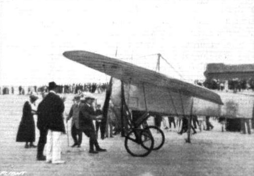
Another reminiscence of the late Second Lieut. Pegoud. - Pegoud, in September, 1913, starting a Bleriot belonging to M. Bleriot at Hardelot, where the famous builder of these aeroplanes has a villa.

Reminiscences of the late Second Lieut. Pegoud. - Pegoud just making his start for Paris in his Bleriot, September, 1913.
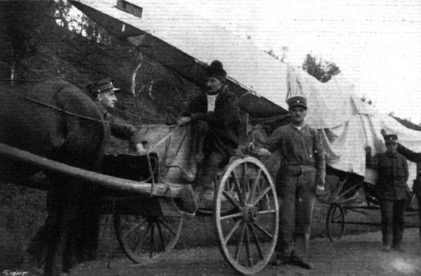
Lieut. Gran transporting his Bleriot by road in the Arctic regions of Norway. - The driver is typical of that part of the country.
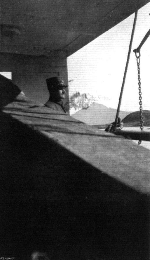
Lieut. Gran on board the steamer with his Bleriot at the moment of crossing the Arctic circle.
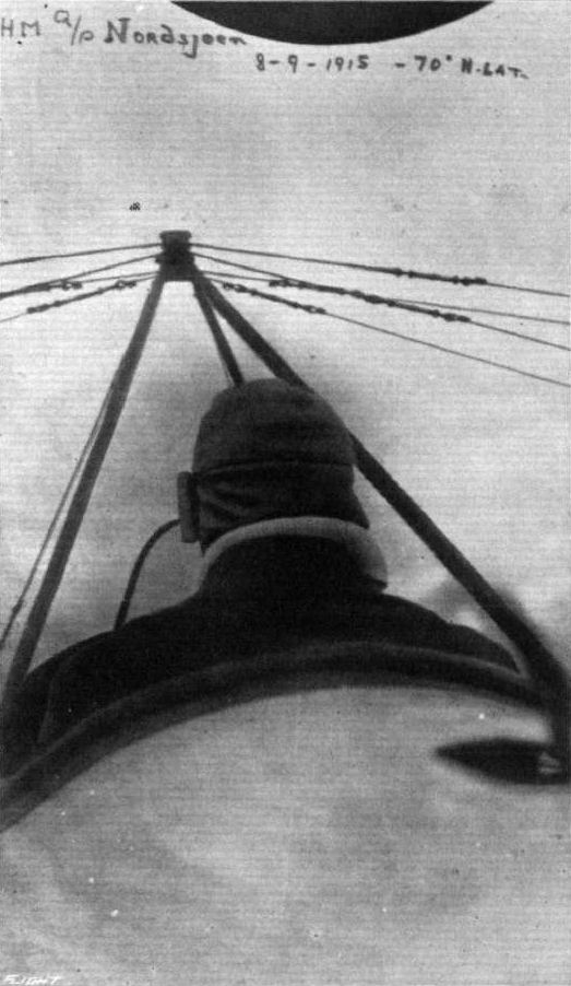
A snap in 70 degs. N. latitude of Lieut. Gran, taken by his passenger at an altitude of 3,000 feet. The machine is one of the Norwegian Royal Flying Corps' two-seater Bleriots, named Nordsjoen (North Sea).
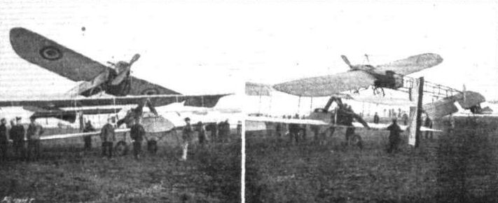
A Unique Atterrissage. - A Bleriot come to rest on the upper wing of a Voisin biplane. The occupants of both machines were none the worse for this little incident.

A scale model Bleriot built by Mr. O. A. Woad, of South Dunedin, New Zealand.
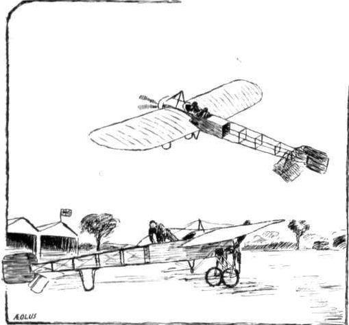

Various French undercarriages.
Flight, November 19, 1915.
CONSTRUCTIONAL DETAILS.-XI.
<...>
Occasionally M. Bleriot has attempted to break away from his standard type of undercarriage, rarely with success however. At the last Paris Aero Show there was exhibited a "pusher" biplane fitted with a somewhat unusual type of chassis, as shown in our second Bleriot sketch, from which the action is fairly evident. The curved channel steel member that carries the wheel is universally pivoted round the lower end of the vertical chassis strut, while to its forward end is attached a shock absorber enclosed in a metal casing. No great amount of success, we believe, attended this design.
<...>
Various French undercarriages.
Flight, February 26, 1915.
THE 160 H.P. ARMOURED BLERIOT TWO-SEATER.
JUST before war was declared, M. Bleriot had started experiments with a new type of armoured monoplane, fitted with a 160 h.p. motor, and although the tests had to be abandoned, the two machines of the type which had been constructed were pressed into service, and both of them # one in the hands of Vedrines # have rendered a good account of themselves at the Front.
As will be seen from the photographs which we reproduce, with the exception of the body and allowing for the difference in size and power, there is comparatively little departure from what may be termed standard Bleriot practice, the wings, which have rather a pronounced dihedral, being identical in general construction and shape to those fitted to the ordinary type of machine. Lateral control is, as usual, effected by the warp of the wings, the warp wires being carried to the bottom pylon, which is enclosed within the body. The top load wires, it will be seen, are attached to the forward end of a double mast of somewhat similar design to that fitted to the "total visibility" type machine, which is mounted upon the body; while the top warp wires are carried up to the rear end of this structure.
The body is of the #coque" type, and is of ample depth, so as to allow the gunner to use his gun either when standing inside the machine or when seated, and to permit of access to the holes at the side of the armoured casing. This casing extends from the extreme forward end of the body to the rear of the gunner's seat, and is made of 3 mm. chrome nickel steel, thus completely enclosing the engine # a 160 h.p. Gnome # the pilot, gunner, all tanks and the controls, and affording the maximum amount of protection against the effects of small gun and rifle fire; while the underneath portion of the body is well rounded, so as to minimise the penetrating power of a projectile, which strikes the armour at an angle. Suitably positioned holes are cut in the nose of the machine to allow of the entrance of sufficient air to cool the engine; and doors are provided, one on each side, beneath the wings and near the front (see the three-quarter front view), through which the gunner can fire at an object beneath the machine. The remainder of the framework of the body is embedded within a papier-mache casing, over which canvas is sewn, with the object of minimising the risk of failure of a machine in the air in the event of the framework being struck by a bullet; as it has been proved by experiment that the wood does not so readily splinter when enclosed in this fashion, as when exposed with no support.
The tail and the undercarriage call for little comment, as they so closely follow the usual Bleriot practice. The tail skid is similar to that on the Bleriot monocoque which was exhibited; at the last Paris Show, being attached by wires and shock absorbers to the body and to the tail.
During tests conducted in France the machine was loaded up with a weight of 165 lbs. to compensate for the absence of armanent and projectiles, and the weight of the pilot, passenger and accessories amounted to 375 lbs., while sufficient fuel and oil was carried to enable a three hours' flight to be made. Under these conditions of loading it was required to attain a speed of 130 kiloms. per hour (81 miles per hour) in straight flight, be capable of climbing at the rate of 1,000 metres in ten minutes (328 ft. per min.), and land within a field of not more than 100 metres (109 yards in length). It speaks well for the design of the machine that despite the heavy load carried it was easily able to satisfy these requirements.

THE 160 H.P. ARMOURED BLERIOT TWO-SEATER. - A three-quarter front view.

THE 160 H.P. ARMOURED BLERIOT TWO-SEATER. - A three-quarter rear view.
Flight, November 19, 1915.
CONSTRUCTIONAL DETAILS.-XI.
<...>
Yet a different form of undercarriage was that of the Breguet biplanes, which was of the four-wheeled variety, as shown in one of the accompanying sketches. The main load is taken by two wheels mounted on a tubular axle, which is, in turn, supported on a pair of telescopic steel tubes with which are incorporated coil springs.
Another pair of wheels is mounted well out in front for the protection of the propeller and to prevent the machine from turning over on its nose in a rough landing. In order to facilitate steering on the ground at low speeds these front wheels are so mounted that their axle can oscillate in a vertical as well as in a horizontal plane. The detail sketch will help to make the exact method clear.
The Breguet chassis as well as the whole machine was, it may be recollected, made entirely of steel, the tubes, in the case of the undercarriage, being given an . approximate streamline form by means of aluminium casings.
<...>
Various French undercarriages.
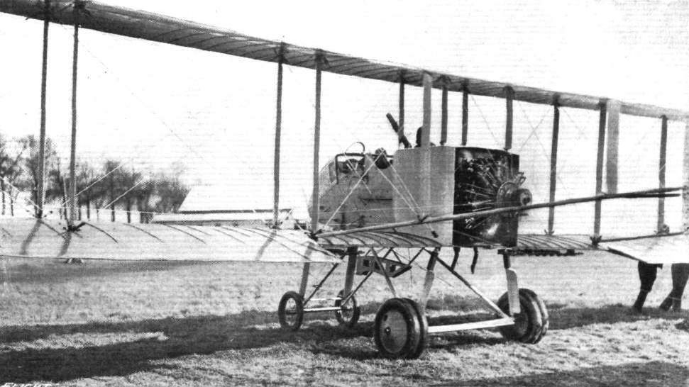
Three-quarter view from behind of one of the latest fighting biplanes used by the French Aviation Corps. This machine is not, as might be supposed, a Voisin, but a Breguet fighting biplane of the engine-bebind type. The gunner, it will be noticed, sits behind the pilot. Below the nacelle may, be seen the bomb-dropping device. The engine is a Salmson-Canton Unne.
Flight, January 1, 1915.
EDDIES.
News reaches us again of the doings of Mr. Delfosse Badgery, who has been giving numerous exhibition flights in various portions of the Southern Hemisphere. The latest accounts of his evolutions appear in the Tasmanian Mail, whose reporter has evidently still a good deal to learn about aeroplanes, to judge from his more picturesque than technically correct descriptions of Mr. Delfosse Badgery's exploits. According to the abovementioned paper, Mr. Badgery had arranged to give demonstrations, which incidentally were the first to be given in public in Tasmania, at the show ground at Elwick. After chronicling the notabilities present at the meeting in the approved style, this valuable journal proceeds to describe the first flight, in the following words :-
"After a considerable wait, the machine, a biplane of the Cordarian type (!) driven by a 45 h.p. Anzani motor, was pulled out from under its canvas tent on to the oval, running along the ground easily on its rubber-tired chassis wheels, and the City Band played 'See the conquering hero comes.' The airman, clad in black rubber overalls and the regulation tight-fitting, bonnet-shape head-gear of the same material, took his seat on the biplane. The tractor screw (unlike the monoplane, the biplane screw acts as a tractor in front, instead of as a propeller) having been set spinning round, the four men holding the machine back released their grip, and the machine instantly shot forward, ran along the ground about 30 or 40 yards, then rose rapidly and gracefully, like a soaring bird over the land, in the direction of Glenorchy."
Flight, January 8, 1915.
EDDIES.
MR. A. W. JONES continues to do a lot of good missionary work in Australia, where, it will be remembered, he is flying a Caudron biplane. In a letter from Brisbane, Mr. J. Morgan, his manager, gives the following account of some of Mr. Jones's experiences :- "People came 200 to 300 miles to see the flights in North Queensland, the Caudron being the first machine to fly in 'Caions.' It was a very bad day, blowing 40 m.p.h., and the country round was heavily timbered. After going about 10 miles Mr. Jones decided to land in a sugar plantation, but was upset before reaching it. It took about two hours to find the machine, as we had to force our way through dense scrub. The pilot was not anywhere about, and we got rather scared, as there was a swamp infested with alligators nearby. (I shot one myself two days afterwards, measuring 12 feet.) Mr. Jones eventually turned up at a Chinaman's camp, where, it appears, he had been carried unconscious by two Chinamen, but he quickly recovered and was quite unhurt. It took two days to rescue the bits of the machine, as we had to chop our way through two miles of scrub.
"Some aboriginals put us on the track of the machine, saying that they saw 'big hawk' fall, but we could not persuade them to go anywhere near it."
One of the photographs which appear on this page is helpful in emphasising Mr. Jones's little adventure.
Flight, February 5, 1915.
EDDIES.
I do not happen to know who at present holds the record for the shortest period of tuition, or whether it still stands to the credit of Lieutenant N. Pemberton-Billing (his would assuredly take a lot of beating), but a very creditable performance was that of one of the pupils at the Hall school, Mr. J. Lloyd Williams, of the Public Schools and University Corps, Royal Fusiliers, who has just obtained his brevet after only 163 minutes, or 2 hours 43 minutes, tuition, covering a period of 13 days. Mr. Lloyd Williams was in camp at Epsom with his Battalion, and was therefore only able to attend the school once or twice a week, having to obtain special permission from his commanding officer each time. The "ticket" was a very good one, and in the altitude test the barograph registered 1,650 ft. By the way, I hear that quite a number of the members of this corps have joined, or are joining, the R.F.C., so that we may expect to hear further of some of them if Mr. Lloyd Williams may be taken as a fair example of the corps.
"AEOLUS."
EDDIES.
News reaches us again of the doings of Mr. Delfosse Badgery, who has been giving numerous exhibition flights in various portions of the Southern Hemisphere. The latest accounts of his evolutions appear in the Tasmanian Mail, whose reporter has evidently still a good deal to learn about aeroplanes, to judge from his more picturesque than technically correct descriptions of Mr. Delfosse Badgery's exploits. According to the abovementioned paper, Mr. Badgery had arranged to give demonstrations, which incidentally were the first to be given in public in Tasmania, at the show ground at Elwick. After chronicling the notabilities present at the meeting in the approved style, this valuable journal proceeds to describe the first flight, in the following words :-
"After a considerable wait, the machine, a biplane of the Cordarian type (!) driven by a 45 h.p. Anzani motor, was pulled out from under its canvas tent on to the oval, running along the ground easily on its rubber-tired chassis wheels, and the City Band played 'See the conquering hero comes.' The airman, clad in black rubber overalls and the regulation tight-fitting, bonnet-shape head-gear of the same material, took his seat on the biplane. The tractor screw (unlike the monoplane, the biplane screw acts as a tractor in front, instead of as a propeller) having been set spinning round, the four men holding the machine back released their grip, and the machine instantly shot forward, ran along the ground about 30 or 40 yards, then rose rapidly and gracefully, like a soaring bird over the land, in the direction of Glenorchy."
Flight, January 8, 1915.
EDDIES.
MR. A. W. JONES continues to do a lot of good missionary work in Australia, where, it will be remembered, he is flying a Caudron biplane. In a letter from Brisbane, Mr. J. Morgan, his manager, gives the following account of some of Mr. Jones's experiences :- "People came 200 to 300 miles to see the flights in North Queensland, the Caudron being the first machine to fly in 'Caions.' It was a very bad day, blowing 40 m.p.h., and the country round was heavily timbered. After going about 10 miles Mr. Jones decided to land in a sugar plantation, but was upset before reaching it. It took about two hours to find the machine, as we had to force our way through dense scrub. The pilot was not anywhere about, and we got rather scared, as there was a swamp infested with alligators nearby. (I shot one myself two days afterwards, measuring 12 feet.) Mr. Jones eventually turned up at a Chinaman's camp, where, it appears, he had been carried unconscious by two Chinamen, but he quickly recovered and was quite unhurt. It took two days to rescue the bits of the machine, as we had to chop our way through two miles of scrub.
"Some aboriginals put us on the track of the machine, saying that they saw 'big hawk' fall, but we could not persuade them to go anywhere near it."
One of the photographs which appear on this page is helpful in emphasising Mr. Jones's little adventure.
Flight, February 5, 1915.
EDDIES.
I do not happen to know who at present holds the record for the shortest period of tuition, or whether it still stands to the credit of Lieutenant N. Pemberton-Billing (his would assuredly take a lot of beating), but a very creditable performance was that of one of the pupils at the Hall school, Mr. J. Lloyd Williams, of the Public Schools and University Corps, Royal Fusiliers, who has just obtained his brevet after only 163 minutes, or 2 hours 43 minutes, tuition, covering a period of 13 days. Mr. Lloyd Williams was in camp at Epsom with his Battalion, and was therefore only able to attend the school once or twice a week, having to obtain special permission from his commanding officer each time. The "ticket" was a very good one, and in the altitude test the barograph registered 1,650 ft. By the way, I hear that quite a number of the members of this corps have joined, or are joining, the R.F.C., so that we may expect to hear further of some of them if Mr. Lloyd Williams may be taken as a fair example of the corps.
"AEOLUS."
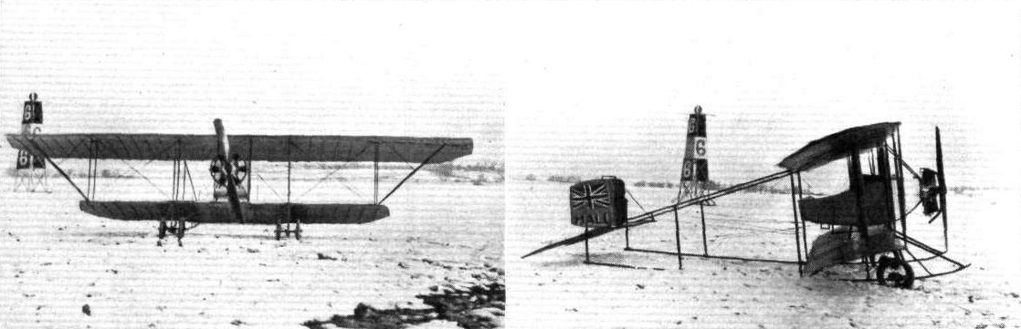
The new Hall School biplane, Caudron type, at Hendon, under the mantle of winter.
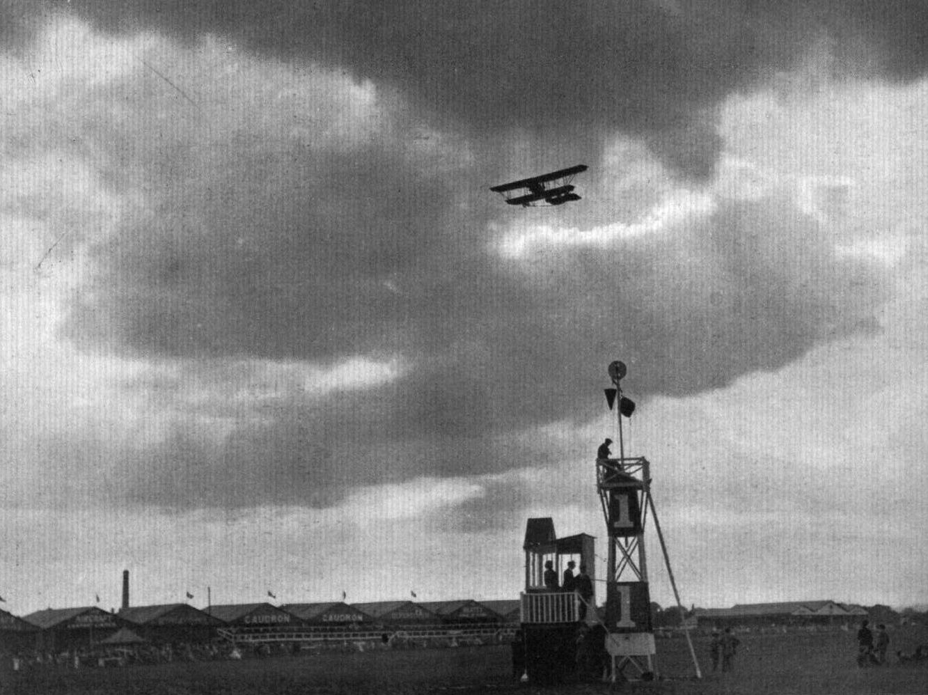
SILHOUETTED AGAINST THE CLOUDED SUN. - A beautiful snap at Hendon Aerodrome last year of Rene Desoutter on a Caudron biplane.
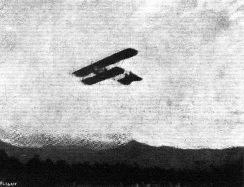
Mr. A. W. Jones' Caudron biplane in flight in North Queensland. This.was the first aeroplane to fly in Caions.
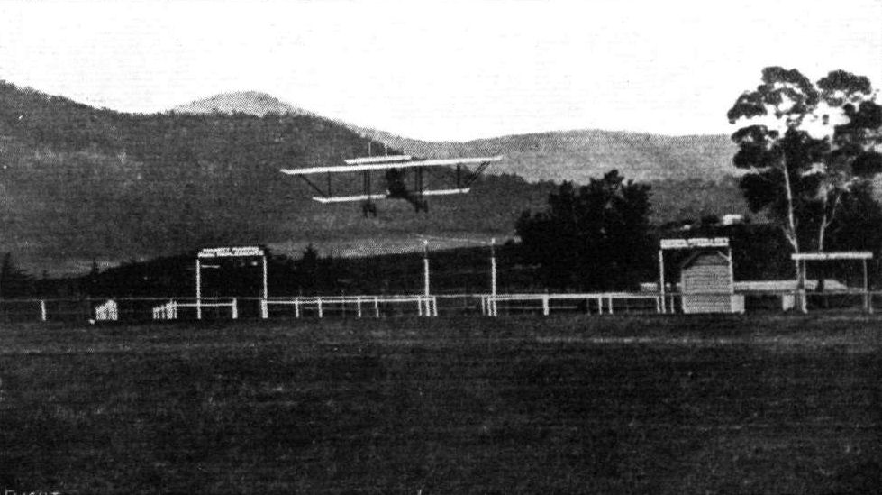
Mr. Delfosse Badgery flying his 45 h.p. Anzani-Caudron-type biplane at Elwick Racecourse, Hobart, Tasmania.

Mr. J. Lloyd Williams, who took his ticket at the Hall Flying School, Hendon, in 163 mins.' actual training time spread over 13 days.
A recent photograph of a number of pupils and machines of the Hall Flying School, Hendon. Mr. Hall is standing in front of machine No. 4, on right of propeller.
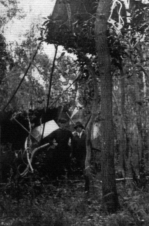
Mr. A. W. Jones' machine in trouble in the wilds in North Queensland.
Flight, October 22, 1915.
CONSTRUCTIONAL DETAILS.-VII.
<...>
Another form of double skid undercarriage is shown in the sketch illustrating the Caudron chassis. Here, as in the Farmans, the skids are supported on struts running up to the lower wing, but the skids are extended right back to the tail, and form, in fact, the lower booms of the outrigger carrying the tail planes. An excellent retarding effect when landing is one of the immediate results obtained by these long skids, and the Caudrons probably pull up more quickly than any other machine of similar weight and area.
<...>

From Above. - Pekin, taken from one of the twenty Caudron biplanes of the Chinese Aviation Corps purchased before the present war. China is now securing further aeroplanes from the United States. - (By courtesy of Flying, U.S.A.)
Various types of double skid undercarriages.
Flight, October 22, 1915.
EDDIES.
About the photo, on this page of the "strafed" Caudron, Noel explains that the machine was hit by a German shell almost in the motor when at a height of 2,200 metres. The 'bus caught fire, and things looked pretty serious for the pilot, who, thanks partly to his other motor and partly to sheer good piloting, managed to get back safely to the right side of the French lines.
In another photo, is seen a batch of French avions, which includes M. Farmans, Caudrons, Morane "parasols," and Nieuport scouts. The latter, of which we published illustrations and particulars some months ago, are, I believe, proving highly successful, a fact which, as they are modelled on the lines of our scouts, is no mean compliment to the Sopwith Aviation Co., who were the first to demonstate the high value of this type of machine as long ago as the summer of 1913.
Flight, December 3, 1915.
THE BRITISH-BUILT TWIN-ENGINED CAUDRON BIPLANE.
AFTER the success attained by the original French twin-engined Caudron biplanes, it is not surprising that the British Caudron Co. turned their attention to the production of similar machines and, judging from the air-work that the first of the British-built biplanes has already done during the comparatively short period since it was first tested, there seems to be every reason to expect that it will worthily uphold the reputation established by its French prototypes.
During the preliminary trials carried out a short time ago, the machine fulfilled in every way the expectations of its constructors. Without giving actual figures, it is possible to state that carrying capacity, speed, and climb are all very good, and the acquisition of a number of machines of this type should prove a valuable addition to the equipment of our Air Services.
That the development of the large machine of the future, as we have stated on more than one occasion in the past, will in all probability lie along the lines of the aeroplane with two or more engines has always appeared natural to us, partly on account of the distribution of the main load thereby obtained (although we are aware that this advantage is accompanied by certain disadvantages) and partly because this arrangement allows of using the types of engines already available when high power is desired. Another point in favour of the employment of two or more engines, and one which, by the way, has been most forcibly demonstrated by one of the French prototypes of the machine under review, and illustrated in our columns not long ago, is that in this way putting all one's eggs into one basket is avoided. Should one engine peter out, either owing to internal trouble or to damage by hostile shells, the other will give sufficient power to enable the pilot to regain his own lines under circumstances when this would have been impossible even with the flattest glide of a single-engined machine,
However, reverting to the first "twin" built by the British Caudron Co., our readers may form a very good opinion of its general arrangement from the accompanying photographs. Each of the Anzani engines is mounted in a little nacelle, which serves the double purpose of supporting the engine and its tanks, enclosing the latter in a streamline casing. The method of supporting each engine on one half of the chassis by "Vee" struts is one of the many good points of this machine, forming, as it does, a structure of great strength. Pilot and observer are comfortably installed in the central nacelle, both obtaining a very good view forward as well as downward on account of their respective positions.
Apart from the question of engines there is no radical departure from ordinary Caudron practice. The main planes are characterised by the same flexible trailing edge which has always been one of the outstanding features of Caudron machines, and one to which, no doubt, they owe a large proportion of their good stability. As in earlier models, the upper plane is of considerably greater span than the lower, the overhang being braced by struts running out diagonally from the outer inter-plane struts. One departure from standard Caudron practice will be noticed in the reduction of the amount of trailing edge of the lower plane.
From the accompanying illustrations it will be seen that the usual flexible elevator has been discarded and in its stead one of the hinged, divided type fitted. The tail plane, the angle of incidence of which is adjustable, is surmounted by four small triangular fins to which are hinged the four rudders. This large rudder area has, of course, been necessitated by the extra amount of vertical side area presented by the three nacelles, and also partly by the fact that the two inner rudders do not receive any of the "slip" from the propellers. When flying with only one engine running a large rudder area is also essential in order to counteract the turning couple. Owing to the long skids, which act as very efficient brakes when landing, the twin-engined Caudron biplane pulls up comparatively quickly, an advantage not otherwise easily obtained, as will be readily understood when it is considered that the momentum of such a great mass as that presented by two big engines, pilot and observer, and the weight of the machine itself, is of a very considerable magnitude. Constructionally the Caudron "Twin" is exceedingly well made, the workmanship and finish being of a very high standard. Some of the detail fittings, of which no description may be given at present, are highly ingenious, and are evidently the work of men who are experts in their own particular line of work. In conclusion, we wish to congratulate the British Caudron Co. on this very fine piece of work, and would express the hope that this machine may be followed by many more, and that further development along the same lines may be made to the mutual benefit of our Air Services and the Caudron Co.

A snap somewhere "over there" from a Caudron biplane at a height of 2,000 feet. The machine in mid-air below is Louis Noel's Maurice Farman.
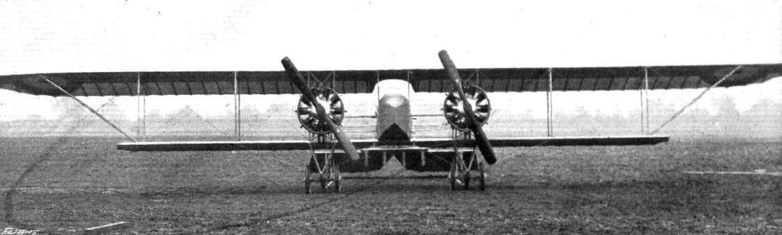
The twin-engined Caudron from in front.

Side view of the twin-engined Caudron.
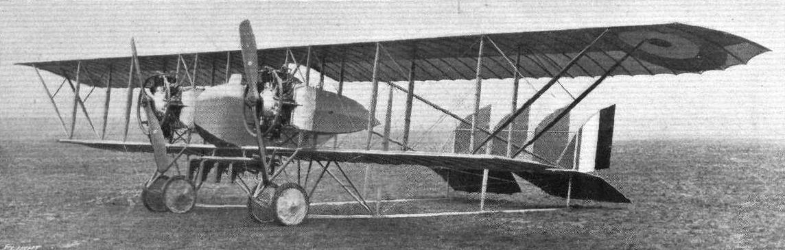
Three-quarter view from in Front of the twin-engined Caudron.

Three-quarter view from the rear of the twin-engined Caudron.
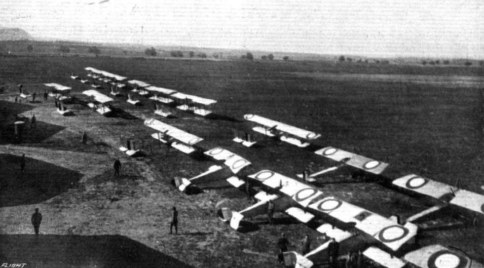
A fleet of avions at an air station "somewhere in France."
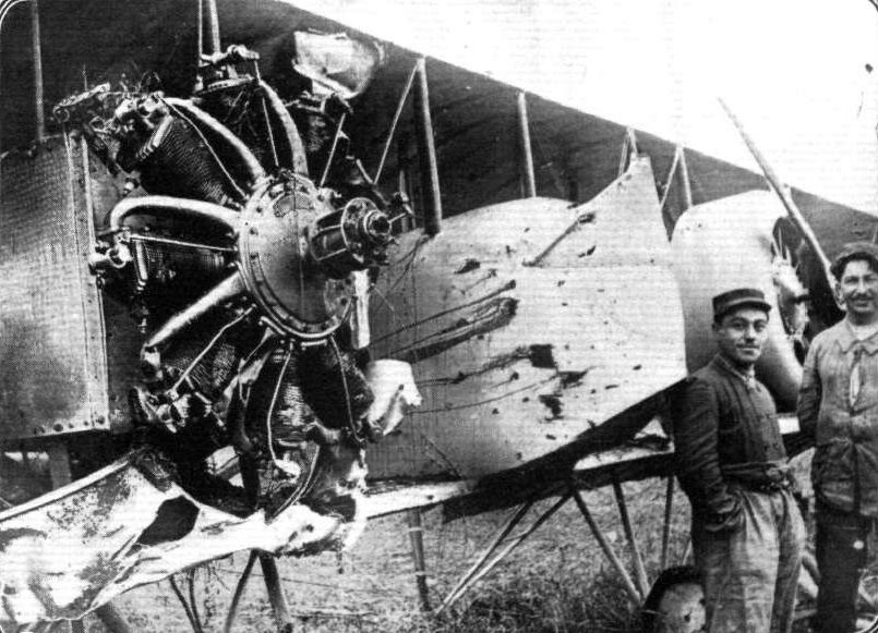
An excellent demonstration of the advantage of twin-engined machines. A Caudron biplane somewhat severely "strafed" by German shell fire.
Flight, November 5, 1915.
CONSTRUCTIONAL DETAILS.-IX.
<...>
The Clement Bayard monoplane, which was also exhibited at the last Olympia Show, had a similar type of Vee chassis, with the exception, however, that ordinary circular steel tubes were used in its construction, the necessary streamline form being obtained by enclosing the tubes in wood casings of the desired section. The two stub axles move between two transverse steel tubes connecting the apexes of the struts, and the manner in which springing is obtained by means of rubber shock absorbers is clearly shown in the detail sketch.
<...>
Various undercarriages of the "Vee" type.
Flight, April 30, 1915.
EDDIES.
Perhaps few of the captures made by the German army have been hailed with greater satisfaction in German aeronautical circles than was the occupation of the Rheims aviation centre in the early part of the war. Their aviation journals have certainly not failed to make the most of the coup by telling credulous readers of the rich booty in the way of engines and modern aeroplanes, of both the mono- and biplane type, which was raked in. Unfortunately - for the German journals - the photographs illustrating these voluble accounts fail to show a single up-to-date aeroplane. In one of the accompanying photographs a German officer is seen standing on the wings of a partly wrecked Deperdussin monoplane, in an attitude suggestive of a gladiator of old, appealing to an appreciative audience for the sign "thumbs up" or "thumbs down." The pose, however, loses much of its apparently intended effect when one looks a little closer at the machine, which will be readily recognised as being of the type used in this country at the time of the first Circuit of Britain. Although these monoplanes were excellent machines in their day, the capture of a few of them by the Germans need not be greatly lamented, since they could not have been of much service for war purposes. One cannot help thinking how much this officer's pose would have gained in dignity, had his booted feet been resting on the wings of a modern Dep. monocoque, or even one of the type similar to the monoplane on which Commander Porte did such excellent flying at Hendon in the pre-war days.
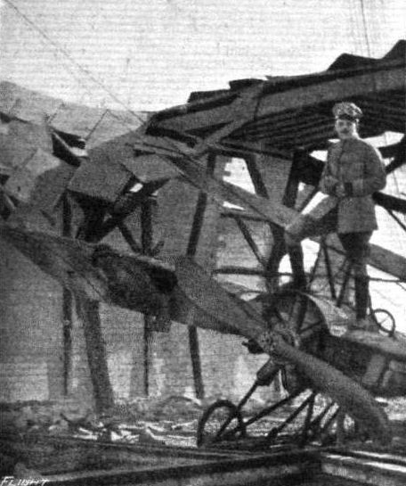
Photograph showing a portion of a wrecked hangar at Rheims and the remains of an old Dep. monoplane.
Flight, November 19, 1915.
CONSTRUCTIONAL DETAILS.-XI.
<...>
Another undercarriage that neither belonged to the skid nor to the "Vee" type was that of the last Deperdussin monoplanes. In this the framework of the chassis consists of two "U" shaped members built up of a number of laminations of wood, and attached with their upper ends to a longitudinal strip of wood running alongside and bolted to the sides of the body. The tubular axle rests on the lower curved portions of the "U," from which it is sprung by simply wrapping rubber cord around it and the bottom of the "U." The attachment of the lift cables is shown in one of the detail sketches, and is mainly interesting on account of the fact that these cables run right across from one wing to the other, being merely gripped by a steel plate where they pass under the ledge-shaped projection on the leading edge of the chassis struts.
<...>
Various French undercarriages.
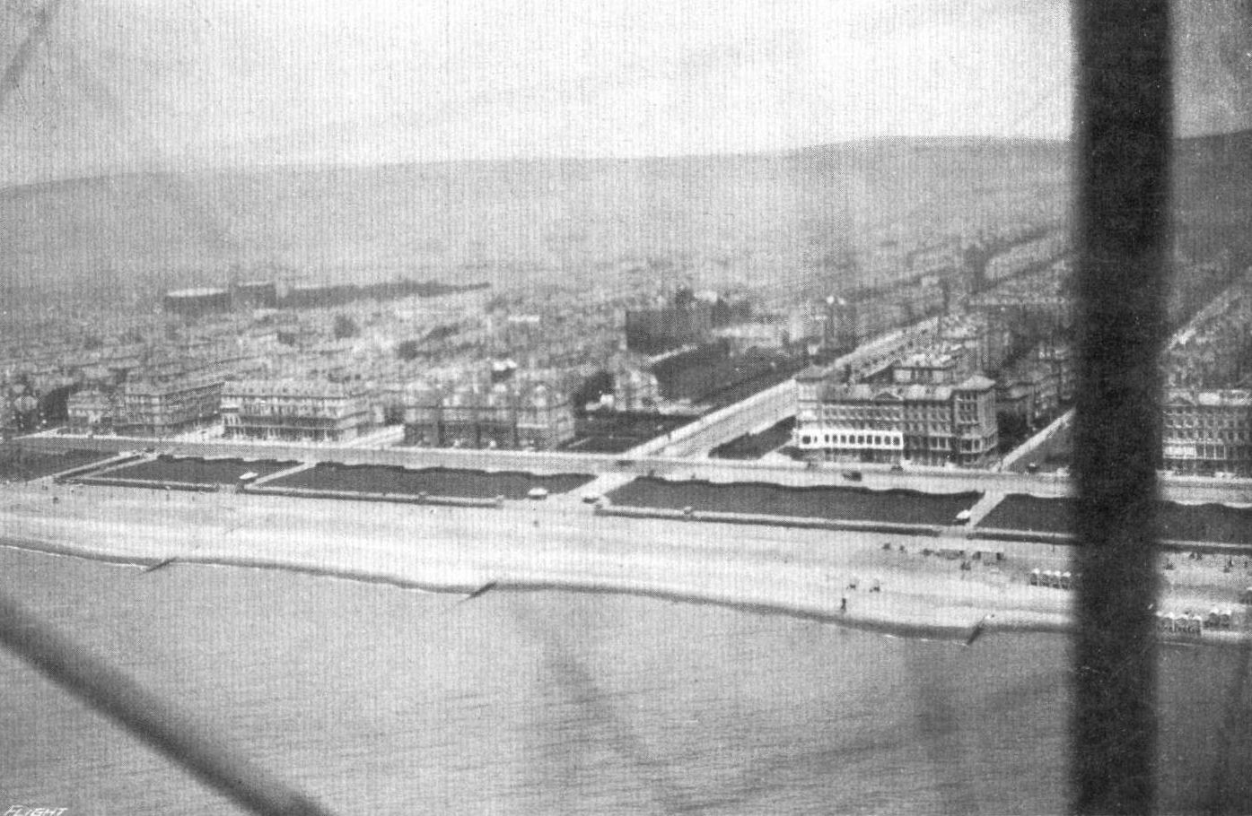
FROM ABOVE. - The Lawns, Hove, from the snap taken by Mr. Clarence Winchester from Mr. Eric Pasbley's biplane last year.
Flight, October 22, 1915.
CONSTRUCTIONAL DETAILS.-VII.
<...>
As the Farman type of undercarriage may be said to be the progenitor of the wheel and skid combination, this will be dealt with first. The accompanying illustrations show a modern Henry and Maurice Farman chassis. The chief characteristics are, it will be seen, that there are two pairs of wheels, each pair mounted on a short axle slung from the corresponding skid by means of rubber bands. The skids or runners are in turn supported on a structure of streamline struts running down from the spars of the lower wing. This arrangement, while suffering from the disadvantage that shock is transmitted to the spars, gives a very wide track, and consequently good stability when rolling over the surface.
The disadvantage of the arrangement is not very serious, and can be almost completely overcome by proper bracing with steel wires or cables.
<...>
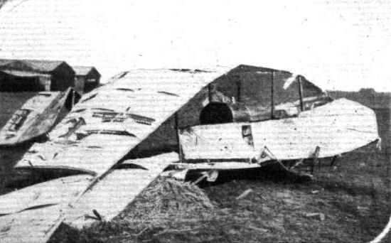
WOUNDED FLYER. - A Henry Farman biplane brought down by shell fire.
Various types of double skid undercarriages.
Flight, November 19, 1915.
CONSTRUCTIONAL DETAILS.-XI.
<...>
The last of our chassis sketches on this week's full-page illustrations shows the undercarriage of the curious H. Farman "one-and-a-half-plane" that was exhibited at the last Paris Aero Show (1913). The wheel track is very wide - 4 metres, to be exact - and the two comparatively long stub axles, which have their inner ends pivoted to the front spar of the lower plane, are given an upward twist at their outer ends in order to bring the wheels into a vertical position. The two struts that support the wheel axle through rubber shock absorbers form a "Vee" as seen from the side, being secured at the top to the front and rear spars of the lower plane and converging to form the angle in which the axle rests. The wide track of this undercarriage, whilst rendering the machine practically immune from turning over sideways, or "cartwheeling" when on the ground, made the machine somewhat difficult to steer on rough ground owing to the long "leverage" of the wheels when encountering an obstacle.
Various French undercarriages.
Flight, May 21, 1915.
EDDIES.
What happens to the aeroplanes captured during the war? This is a question that has often been asked, and one which is not readily answered, since it is not easy to obtain authentic information on the point. Just now and again a little daylight is let in upon the mystery. For instance, a Taube and an Aviatik have been and probably are still on view in Paris, and I would not be surprised if anyone told me there are a couple of captured German aeroplanes down at Farnborough - an L.V.G. biplane and a Fokker monoplane. It has not, so far, emerged that the Allies employ captured enemy machines even if these happen to fall into our hands in a serviceable condition. In the majority of cases the probabilities are that a machine brought down is either badly damaged in landing or else is deliberately set on fire by the pilot. Besides, the utility of a captured enemy aeroplane is a questionable asset, as - to point a moral - a great number of the German planes are readily distinguished from those of the Allies, and the substitution of a Union Jack for the black cross would hardly prevent such a machine from being fired on by our own troops, if flying at any height, even granting for the moment its usefulness for raids over German territory. On the other hand, the accompanying illustration, taken from Flugsport, seems to indicate that the Germans do employ captured French machines. It will be seen that the rosette of the French colours has been obliterated from the wings of this captured Maurice Farman biplane and the black cross substituted. The nose of the nacelle has been "decorated" (or the reverse, according to taste) with the German eagle. Whether this machine is employed for actual war service or not it is impossible to say, but the crosses and eagle seem to point to such an object being in view. This supposition is further strengthened when one knows that the Germans are actually building imitations of French machines, two firms for instance - the Fokker and the Hanuschke - having constructed monoplanes which could not possibly be distinguished from Morane-Saulnier monoplanes when flying at anything above a few hundred feet.

IN THE SPORTING AND RACE DAYS AT HENDON DURING LAST YEAR. - Mr. Pierre Verrier rounding a pylon during a heat.

AT THE RAILWAY END OF THE HENDON AERODROME. - A last season's snap, showing Pierre Verrier rounding No. 2 pylon on a Maurice Farman.
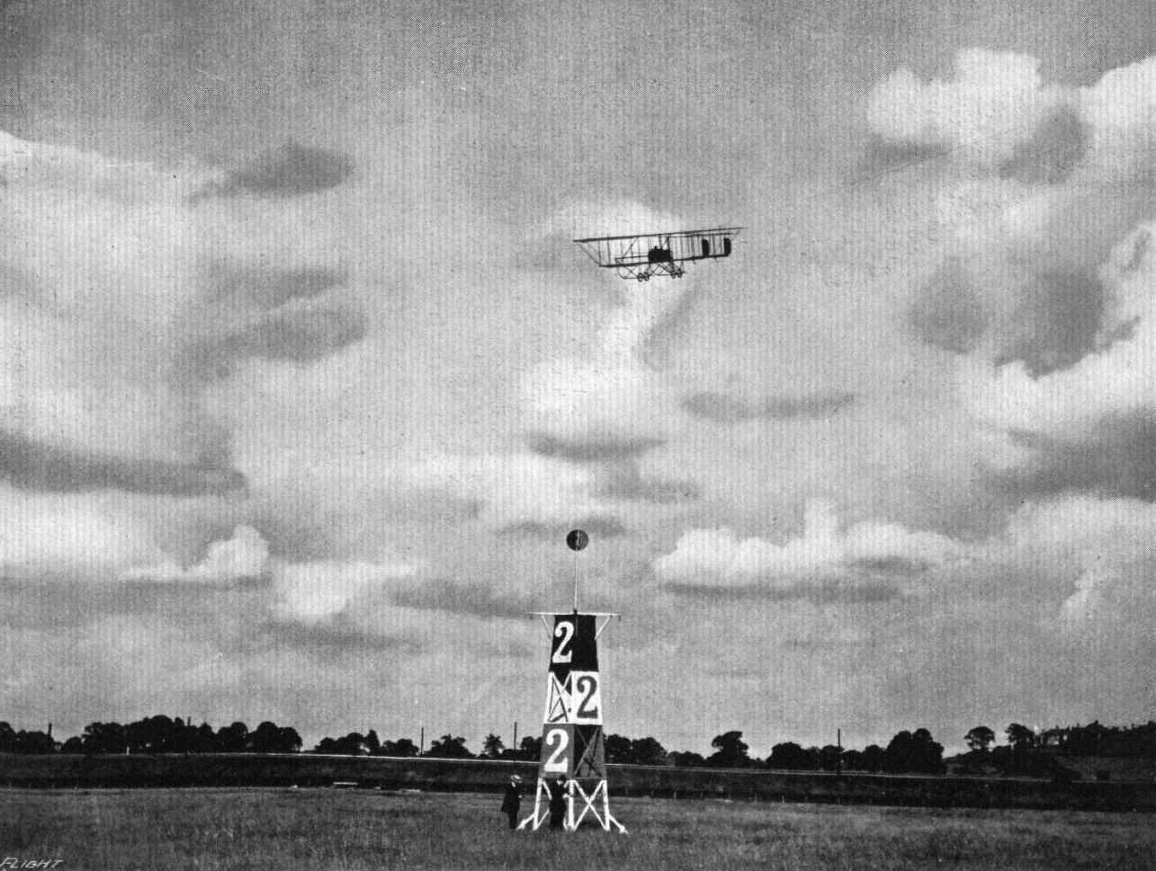
WHEN THE PUBLIC USED TO GATHER AT HENDON. - A reminiscence of Flight Commander Claude Grahame-White on a Maurlce-Farman biplane.
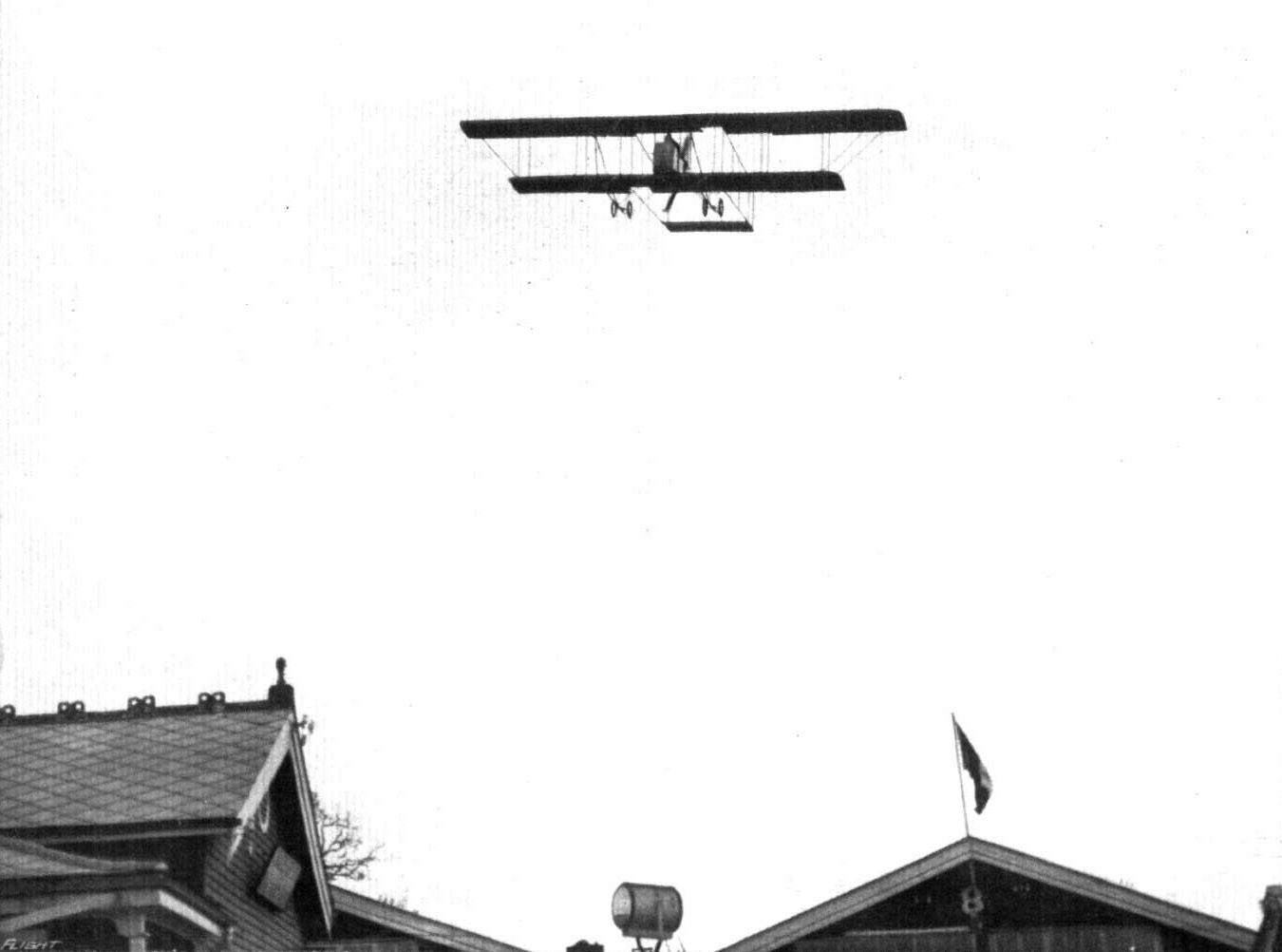
Mr. F. W. Merriam with a pupil on a Maurice Farman, coming in over the sheds at Hendon.
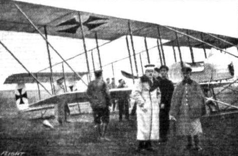
A Maurice Farman biplane captured by the Germans.

SOMEWHERE WITH THE GALLIPOLI EXPEDITION. - A British seaplane just after its return from a reconnaissance.
Flight, October 22, 1915.
CONSTRUCTIONAL DETAILS.-VII.
<...>
As the Farman type of undercarriage may be said to be the progenitor of the wheel and skid combination, this will be dealt with first. The accompanying illustrations show a modern Henry and Maurice Farman chassis. The chief characteristics are, it will be seen, that there are two pairs of wheels, each pair mounted on a short axle slung from the corresponding skid by means of rubber bands. The skids or runners are in turn supported on a structure of streamline struts running down from the spars of the lower wing. This arrangement, while suffering from the disadvantage that shock is transmitted to the spars, gives a very wide track, and consequently good stability when rolling over the surface.
The disadvantage of the arrangement is not very serious, and can be almost completely overcome by proper bracing with steel wires or cables.
<...>
EDDIES.
<...>
In another photo, is seen a batch of French avions, which includes M. Farmans, Caudrons, Morane "parasols," and Nieuport scouts. The latter, of which we published illustrations and particulars some months ago, are, I believe, proving highly successful, a fact which, as they are modelled on the lines of our scouts, is no mean compliment to the Sopwith Aviation Co., who were the first to demonstate the high value of this type of machine as long ago as the summer of 1913.
A snap somewhere "over there" from a Caudron biplane at a height of 2,000 feet. The machine in mid-air below is Louis Noel's Maurice Farman.
A fleet of avions at an air station "somewhere in France."
Various types of double skid undercarriages.
Flight, March 5, 1915.
MODELS.
Mr. W. J. Clark's Morane-Saulnler scale model.
The model shown in the two photographs is a quarter scale model taken from drawings which have appeared in FLIGHT. Span 7 ft. 7.5 ins.; length 5 ft. 4.5 ins.; chord 1 ft. 6 ins. It is driven by a 1/2 h.p. petrol motor, which has not yet been tested, as our correspondent has up to now been too busy. "A friend and myself," says Mr. Clark, "started the Epsom Aero Club about eight months ago, but as several of our members joined the Colours [We shall be glad to receive their names, &c, for publication], it has weakened us a lot, but we hope to pull it up again when times are brighter, and to be able to send you a few more photos, of the models we are constructing."
Flight, March 26, 1915.
EDDIES.
FIRING with a machine gun between the blades of a propeller revolving at something like 1,200 r.p.m. strikes one as being a tricky, not to say risky, pastime, but I have it on good authority that it is the latest exploit of R. Garros the famous French pilot. As to how it is accomplished, at the present time wild horses shall not drag it from me, but the method is extremely neat and simple, and the result is said to have been the bringing down of two Taubes. According to a patent specification in a German paper, an inventive genius over there has patented a device for enabling a machine gun to be fired through the disc area of the propeller by gearing up the trigger of the quick-firer to the engine in such a manner that when a propeller blade is in line with the gun a lock prevents the shot from being fired until the blade has passed out of the line of fire. It is very simple in theory, but difficulties are, I think, more than likely to arise in practice, and I must confess that I do not envy the gunner his task.
Flight, April 9, 1915.
EDDIES.
The first of the series of Morane monoplanes being built by the Grahame-White Aviation Co. have now been completed, and several of them have already been delivered. One of these was put through her acceptance trials last week by Flight Lieutenant B. C. Hucks. Hucks' handling of the Morane is said by those who witnessed it to be absolutely masterly, and the machine, as one would expect from a firm like the G.-W. A. Co., did right well in the tests. As to figures, well these for the time being are best left alone - what with an Editor and a Censor always on the alert, the ways of a staff contributor are far from easy.
"AEOLUS."
Flight, November 5, 1915.
CONSTRUCTIONAL DETAILS.-IX.
<...>
The Morane-Saulnier chassis, already referred to, is shown at the bottom of one of our pages. Viewed from the side it is a simple V, while viewed from in front it represents the letter M. The various members, which are streamline steel tubes, are welded together and form a structure of immense strength. At the top they are joined to steel clips gripping the lower longerons of the body, while at the bottom the outer members are welded together, the angle between them being filled up with a web plate, in which is a slot for the accommodation of the upward travel of the two stub axles, when running over rough ground. Below the portion of the axles that projects through this slot is a short lug to which are anchored the rubber shock absorbers. The inner pair of the four front chassis struts converge towards the centre, where they are welded together and flattened out to accommodate the two transverse members of the chassis between which the axles mine. A bolt passing through from front to back at this point keeps the apex of the inner Vee in place and serves at the same time as a pivot for the stub axles. Another constructional detail which is worth mentioning is the hollow protuberance in the angle between the centre struts, and to which the stay cables are secured by means of adjustment bolts in the manner shown in one of our detail sketches.
<...>
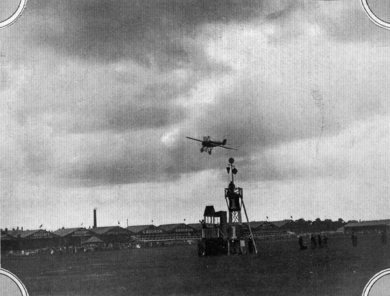
A Morane-Saulnier rounding Pylon I at Hendon, as flown by Mr. W. L. Brock at Hendon Aerodrome during last season.
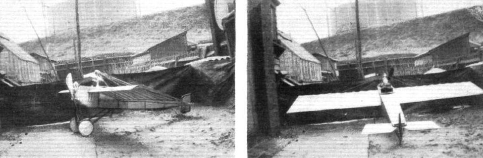
Two views of Mr. W. J. Clark's Morane-Saulnier scale model.
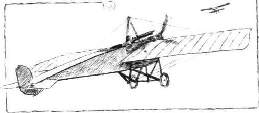

Various undercarriages of the "Vee" type.
Flight, April 16, 1915.
EDDIES.
Although not possessing topical value, having occurred some time ago, a short resume of one of the experiences of the French pilot Gilbert should be of interest. It was in the vicinity of Amiens that Gilbert and his mechanic Bayle were detailed to attack a number of German aeroplanes which were on their way to drop bombs on Amiens. After reaching a height of 2,500 metres in their Morane monoplane, they encountered three Albatros biplanes, which are said to have speedily turned tail on seeing the Morane. Gilbert and his mechanic singled out one, and started in pursuit. They soon overhauled the slower German machine, and at times were flying only fifteen metres apart. Although the hostile aviators were armed with a machine gun, and Bayle only with a cavalry rifle, the Germans seemed distressed, and were constantly dodging about in an endeavour to escape. On one occasion the Albatros dived under the Morane at a distance of a couple of metres only. Bayle says that he thought the Germans intended to ram them, but realising that this was not the case he got in a couple of shots with his rifle. The chase had, unfortunately, to be given up at Montdidier owing to lack of ammunition. On their return to the French lines Gilbert and Bayle, upon examining their machine, found that one bullet had pierced the wing above their heads, while another had first gone through the reserve petrol tank and then through a tool chest in which, amongst other things, were some picture post-cards belonging to Gilbert. The mechanic, who during the pursuit had taken off his gloves in order to be able to handle his rifle better, had his hands so frostbitten, the temperature being 16 degrees below zero, that he had to go to hospital. He is now in flying trim once again, and none the worse for his adventure, whilst amongst his dearest souvenirs is one of the picture postcards pierced by a German bullet and bearing the following inscription by Gilbert: "A mon vieil ami Bayle, d mon devoue- mechanicien, en souvenir de notre chasse a I'Albatros du 18 Novembre, 1914, a Amiens."
"AEOLUS."
Flight, October 22, 1915.
EDDIES.
<...>
In another photo, is seen a batch of French avions, which includes M. Farmans, Caudrons, Morane "parasols," and Nieuport scouts. The latter, of which we published illustrations and particulars some months ago, are, I believe, proving highly successful, a fact which, as they are modelled on the lines of our scouts, is no mean compliment to the Sopwith Aviation Co., who were the first to demonstate the high value of this type of machine as long ago as the summer of 1913.
EDDIES.
Although not possessing topical value, having occurred some time ago, a short resume of one of the experiences of the French pilot Gilbert should be of interest. It was in the vicinity of Amiens that Gilbert and his mechanic Bayle were detailed to attack a number of German aeroplanes which were on their way to drop bombs on Amiens. After reaching a height of 2,500 metres in their Morane monoplane, they encountered three Albatros biplanes, which are said to have speedily turned tail on seeing the Morane. Gilbert and his mechanic singled out one, and started in pursuit. They soon overhauled the slower German machine, and at times were flying only fifteen metres apart. Although the hostile aviators were armed with a machine gun, and Bayle only with a cavalry rifle, the Germans seemed distressed, and were constantly dodging about in an endeavour to escape. On one occasion the Albatros dived under the Morane at a distance of a couple of metres only. Bayle says that he thought the Germans intended to ram them, but realising that this was not the case he got in a couple of shots with his rifle. The chase had, unfortunately, to be given up at Montdidier owing to lack of ammunition. On their return to the French lines Gilbert and Bayle, upon examining their machine, found that one bullet had pierced the wing above their heads, while another had first gone through the reserve petrol tank and then through a tool chest in which, amongst other things, were some picture post-cards belonging to Gilbert. The mechanic, who during the pursuit had taken off his gloves in order to be able to handle his rifle better, had his hands so frostbitten, the temperature being 16 degrees below zero, that he had to go to hospital. He is now in flying trim once again, and none the worse for his adventure, whilst amongst his dearest souvenirs is one of the picture postcards pierced by a German bullet and bearing the following inscription by Gilbert: "A mon vieil ami Bayle, d mon devoue- mechanicien, en souvenir de notre chasse a I'Albatros du 18 Novembre, 1914, a Amiens."
"AEOLUS."
Flight, October 22, 1915.
EDDIES.
<...>
In another photo, is seen a batch of French avions, which includes M. Farmans, Caudrons, Morane "parasols," and Nieuport scouts. The latter, of which we published illustrations and particulars some months ago, are, I believe, proving highly successful, a fact which, as they are modelled on the lines of our scouts, is no mean compliment to the Sopwith Aviation Co., who were the first to demonstate the high value of this type of machine as long ago as the summer of 1913.
A fleet of avions at an air station "somewhere in France."
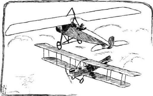
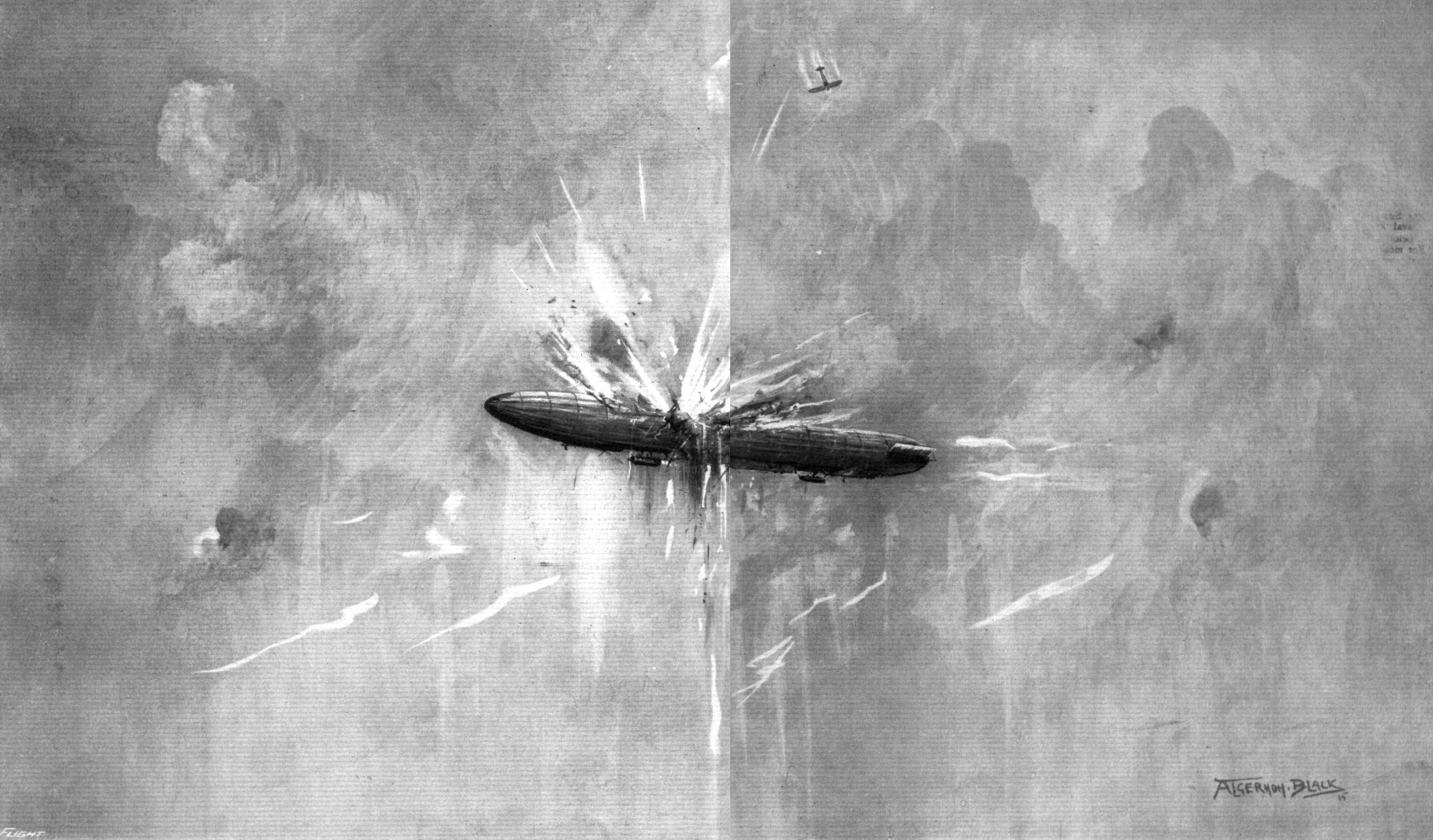
THINNING THE GERMAN AIR FLEET. - The attack in the early morning, by Flight Sub-Lieutenant J. Warneford, V.C., piloting a Morane "parasol," on the Zeppelin airship, near Ghent, on June 7th. For the achievement Lieutenant Warneford was awarded by the King in record time after the deed.
Flight, August 13, 1915.
EDDIES.
After such a series of brilliant feats in the service of La Patrie, it does seem hard luck for two of France's best-known pilots, the two Gs. one might call them, Garros and Gilbert, to have been put out of the running for the rest of the war by one and the same cause, one which is the constant dread of every pilot - engine trouble. While Garros, as is of course well known, is a German prisoner of war, Gilbert's engine took it into its head to strike while over Swiss territory, with the result that he is now interned in that country. It is really rather difficult to say which of the two alternatives is preferable, for while Garros, should the opportunity present itself, can without any scruples take his chances and attempt to escape, Gilbert, being interned in a neutral country, will probably have given his word of honour not to try to escape. In the accompanying remarkable photograph, which we reproduce by courtesy of our French contemporary, L'AEROPHILE, taken from another Avion, Gilbert is seen in his peculiar streamline Morane-Saulnier monoplane, le Vengeur, flying at a good altitude a few minutes previous to a victorious fight with a German Aviatik.
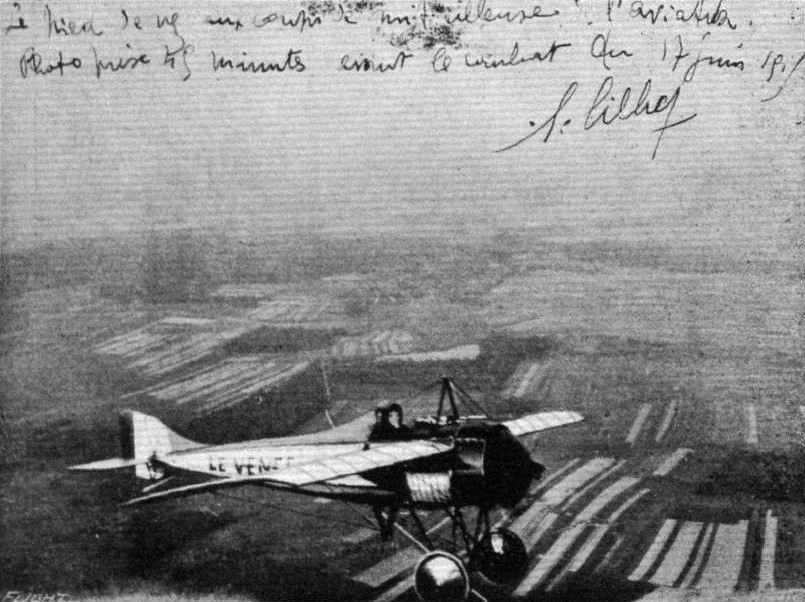
A curious photograph showing M. Gilbert, the well-known French aviator, on his Morane-Saulnier "le Vengeur," taken from another French warplane, on June 17th last, 45 minutes before Gilbert made his attack against one of the enemy's Aviatik machines. Photograph reproduced by courtesy of I'Aerophile.
Captor and Captive. - A German L.V.G. biplane forced to descend by the French aviator, Adjudant N., who was flying the little fast single-seater Morane-Saulnier monoplane seen in the photograph beyond the German machine.
LVG C.II 529/15 downed by Jean Navarre on 20 October 1915. As shown in the magazine photo, Navarre was flying a Morane-Saulnier N fighter at the time.
LVG C.II 529/15 downed by Jean Navarre on 20 October 1915. As shown in the magazine photo, Navarre was flying a Morane-Saulnier N fighter at the time.
Flight, October 29, 1915.
CONSTRUCTIONAL DETAILS.-VIII.
<...>
In the double skid type of chassis illustrated in our last issue the suspension is generally fairly simple, since it is possible to sling the wheel axle by means of strands of rubber from the two skids. When a single, central skid is employed it is no longer possible to solve the problem of elastic suspension quite so simply. There are, however, two or three alternative ways of providing the necessary flexibility. One of these is to make the axle itself flexible. This is generally obtained either by building up the axle in the form of a transverse laminated steel spring which carries on its extremities the two wheels, or by mounting the wheels on two short stub axles, which are then in turn connected at their outer ends to a transverse spring mounted immediately above the axles. In one of the accompanying pages of illustrations will be found two examples of the transverse laminated spring axle. One is the French Nieuport monoplane, and the other the older type Avro biplane. These two undercarriages are similar in type, but differ somewhat in detail. The construction will, we think, be clear from the sketches without needing any explanation, except that in both cases the chassis struts are streamline steel tubes. In the Nieuport the central skid is a steel tube, whereas in the Avro this member is made of ash.
<...>
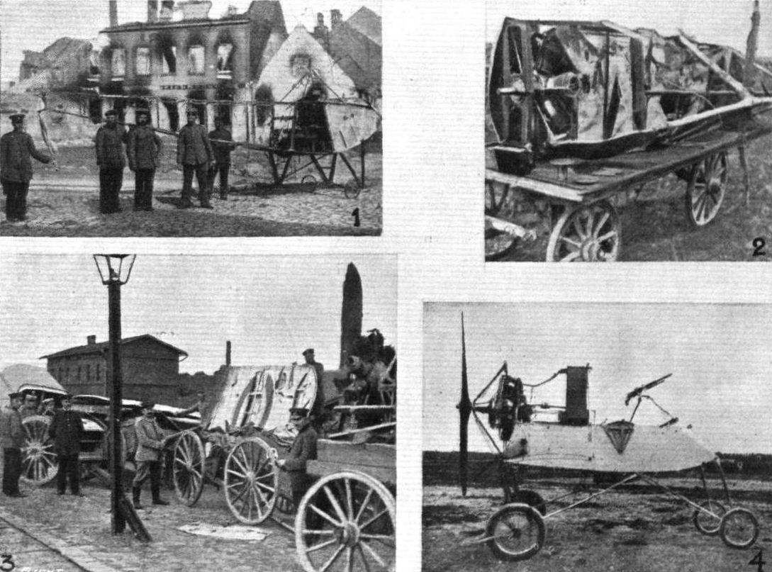
TROPHIES OF WAR. - 1. Fuselage of a Russian monoplane (Nieuport) brought down by the Germans. 2. The remains of a Russian Nieuport. 3. Wreck of a Russian aeroplane being carted away by Germans. 4. Nacelle of a captured French Voisin biplane.
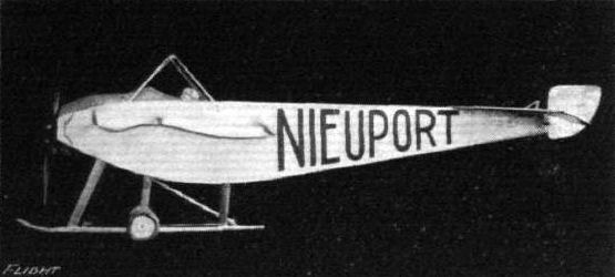
Mr. Richards' scale model Nieuport.
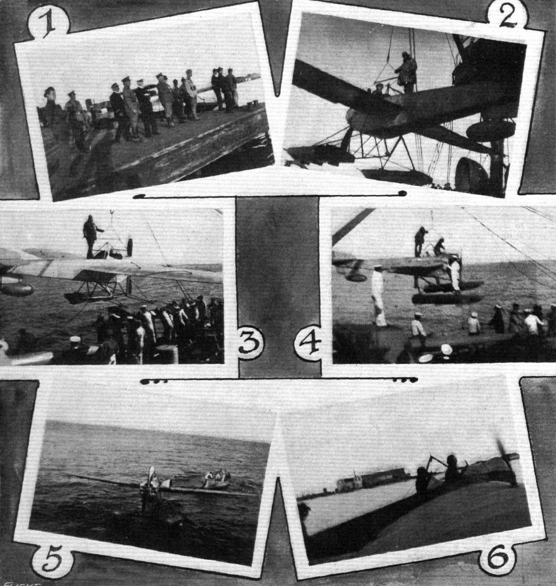
UNSHIPPING AN 80 H.P. NIEUPORT SEAPLANE AT PORT SAID. - 1. General Maxwell and Admiral Pielse watching the operations from ashore. 2, 3 and 4. In process of swinging the Nieuport from the cruiser "Doris." 5. At rest on the sea. 6. Getting away.
Flight, November 5, 1915.
CONSTRUCTIONAL DETAILS.-IX.
<...>
Somewhat similar to the Morane undercarriage is that of the Nieuport scouting monoplane that was exhibited at the last Olympia Aero Show. Some very clear illustrations of this chassis will be found on the same page as the Morane. It will be seen that instead of the inner front struts of the Morane the Nieuport has a single transverse streamline tube, the necessary lateral rigidity being obtained by means of cable bracing. A further difference will be found in the method of guiding the axle. Instead of the slotted web on the Morane a radius rod guides the axle on its upward travel, this radius rod being anchored to a lug on the front edge of the chassis strut. This arrangement, as well as the attachment of the struts to the lower longerons of the fuselage, are illustrated in two of the detail sketches.
<...>
Various undercarriages of the "Vee" type.
Flight, March 19, 1915.
A TWO-SEATER NIEUPORT BIPLANE.
IN the accompanying photographs is seen a biplane which has been recently issued from the Nieuport works. Hitherto the Nieuport firm have chiefly concentrated their energies on machines of the monoplane type, and with the exception of the extra pair of wings their new machine follows very closely on the lines of the monoplanes that made the late Nieuport brothers famous, and it will be noted that everything has been done with the object of improving the views from both pilot's and passenger's seats and to give a gunner as far as possible a free range of firing in any direction.
Generally speaking, this Nieuport military tractor biplane follows standard practice as regards the general arrangement, but upon closer examination several original ideas are noticed.
From the photographs it will be seen that only one pair of struts on each side of the fuselage separates the two planes, and these struts, instead of being parallel to one another, as is usually the case, run to a point on the bottom plane. The reason for this is that the lower plane has only a single spar, which takes the form of a steel tube round which the wing pivots. The upper plane is fitted with two spars in the usual manner, to the rear one of which are hinged the two ailerons. For lateral control a hand lever in front of the pilot operates simultaneously the ailerons on the upper planes, whilst warping, or, more correctly speaking, pivoting, the corresponding half of the lower plane. This system undoubtedly provides ample lateral control. In fact we should imagine that the ailerons on the top plane would alone be sufficient for the maintenance of lateral stability, and the chief advantage in having such a small chord to the lower plane would lie in the fact that it only obscures the downward view to a very slight extent.
As for the arrangement of the gunner's quarters, his seat is placed in the usual manner in front of that of the pilot, and when sitting down inside his cockpit a very wide range of vision is obtained in a downward and forward direction.
In order that the propeller may be avoided when firing forward, there is a circular opening in the top plane through which the gunner can pass the upper portion of his body when standing in his seat. In this position, the muzzle of the gun or rifle is above the circumference described by the tip of the propeller, so that the gun can be fired straight forward, or in an upward direction. Altogether the Nieuport firm is to be congratulated on the machine.
Flight, October 22, 1915.
EDDIES.
<...>
In another photo, is seen a batch of French avions, which includes M. Farmans, Caudrons, Morane "parasols," and Nieuport scouts. The latter, of which we published illustrations and particulars some months ago, are, I believe, proving highly successful, a fact which, as they are modelled on the lines of our scouts, is no mean compliment to the Sopwith Aviation Co., who were the first to demonstate the high value of this type of machine as long ago as the summer of 1913.
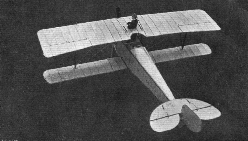
View from above of the Nieuport two-seater biplane, showing the hole in the top plane for the gunner when he wishes to fire in an upward or forward direction.
A fleet of avions at an air station "somewhere in France."
Flight, November 5, 1915.
CONSTRUCTIONAL DETAILS.-IX.
<...>
The remaining two illustrations show the undercarriages of the Vickers scout and Ponnier monoplane. In the Vickers chassis the wheels are sprung, as shown in the sketches, whereas in the Ponnier no springing whatever is provided except that afforded by the pneumatic tyres. This last type of undercarriage may probably be said to be as simple as it is possible to make an undercarriage, and would be of little use on rough ground. It was, as a matter of fact, used on the machine flown by Emile Vedrines in the last Gordon-Bennett race at Rheims.
Various undercarriages of the "Vee" type.
Flight, October 8, 1915.
THE VOISIN WARPLANE.
ATTENTION has been called, from time to time, in our columns to the use made by our enemies of captured French machines for school and other purposes. Thus, it may be recollected, we have given illustrations of a captured M. Farman decorated with the black cross that forms the identification mark of all German military machines.
Among the various types captured by the Germans have also been one or more Voisin biplanes, a fighting machine that has found great favour with our allies across the Channel, who have made, and are making, very extended use of it. As the accompanying illustration, reproduced from Flugsport, shows, the Germans have succeeded in capturing one of these machines intact, and are now employing it for teaching pilots the handling of a type which was considered by their military experts obsolete until French pilots gave practical proof to the contrary. The accompanying scale drawings, which we reproduce by courtesy of our New York contemporary, Aerial Age, and the following description by Mr. Walter H. Phipps, should give a good idea of the general arrangement of this successful French fighting biplane.
"The Voisin gun-carrier, which is the subject of our description this week, is one of the most interesting developments of the European war. It is a type which is rapidly finding favour for offensive purposes, as its size and weight-carrying ability, coupled with its great range of vision and unobstructed mounting for a large machine gun, make it a terror to all machines coming within its range.
"The machine is chiefly characteristic on account of its all-steel construction, a feature which, contrary to previous accepted theory, has found great favour for military work on account of its not being affected by climatic conditions. Other outstanding characteristics of the Voisin machine are the excellent four-wheel shock-absorbing chassis, the small gap between the planes, and the large balanced elevator in the rear.
"The chassis, which is quite different to those fitted to other machines, consists of two sets of wheels, one pair mounted on a single axle at the extreme front of the machine and connected to the nacelle by long telescopic spring absorbers, the other pair directly under the rear main beam and similarly connected by means of shock absorbing -telescopic springs to the rear end of the nacelle. This provides a most excellent landing gear for military work, where landings must frequently be made on very rough ground without fear of capsizing.
"The nacelle or body is built up in the usual way, the construction being mainly wood with steel for the engine and chassis bearers and braces. It provides accommodation for pilot and observer, the former sitting in front with the observer directly in back of him.
"Supported by steel tubes and immediately over the pilot's head is the gun, so mounted that it can easily be handled by the observer, who stands up when working the gun.
"A sloping dash in the nose of the nacelle deflects the air above the heads of the occupants. Behind the passenger's seat and inside the nacelle is mounted a large gasolene tank, sufficient for over 5 hours' flight.
"The engine, 135 h.p. nine-cylinder water-cooled Salmson, is mounted between double bearings in the rear of the nacelle and drives through a long extension shaft a large diameter propeller which revolves behind the main planes. The engine can be started from the passenger's seat by means of a starting handle.
"The main planes, which have a comparatively small gap in relation to the chord, are built up of wooden ribs over steel tube spars. Inter-connected ailerons are fitted to both upper and lower planes, and the chord of the ailerons is greater at the tip than at their inner ends in order to render them more efficient.
"The elevators, which are of tremendous size, are carried on an outrigger formed of four steel tubes, and are unusual in that the elevators, which are of the balanced type, are supported rigidly at only one point on the outrigger, the remainder of the bracing being carried out by wires running to the bottom of the outriggers, and to a short mast on top. Mounted on the rear vertical tube of the outrigger is the large balanced elevator, which is unusual for its great length compared to breadth.
"A refinement worth noticing are the wheel brakes fitted to the rear wheels.
"By means of these brakes, which are operated from the pilot's seat, the machine can be held back by the pilot, whilst running the engine all out, so that it is possible by the aid of these brakes, and the starting handle behind the passenger's seat, to start the machine without any outside assistance whatever, a feature which should prove useful for cross-country work where, after having made a forced landing en route, experienced assistants are not always available, and where the help of inexperienced, though willing, assistants may easily cause considerable damage to the machine. Another advantage of the wheel brakes is that on making a landing in restricted grounds this machine can be brought to a standstill, where others would probably be wrecked by running into obstacles."
Flight, November 5, 1915.
EDDIES.
In spite of the busy-ness of Hendon and the many more or less "near things" that occur almost daily up there, there is no case on record of a machine landing on top of another without, practically, any damage being done to either. The incident illustrated in our photographs occurred at a French aerodrome some little time ago. The machines were both landing, and the Voisin, piloted by an N.C.O. and having a pupil as passenger, was gliding along about six feet from the ground. The Bleriot was also coming down, and the fuselage and wings of the monoplane prevented the pilot from seeing the Voisin. At the instant when the biplane touched the ground the wheels of the Bleriot alighted on its upper plane, and so gentle was the impact that the pilot of the Voisin did not immediately realise that anything unusual had happened. All the repairs that were necessary when the machines had been parted were a new wheel for the Bleriot and a couple of ribs for the top plane of the Voisin.

A captured French Voisin biplane being used by the Germans for school work.
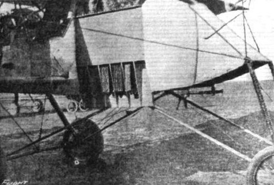
Nacelle of the Voisfn fighting biplane. Note the bomb-dropping arrangement on the side.
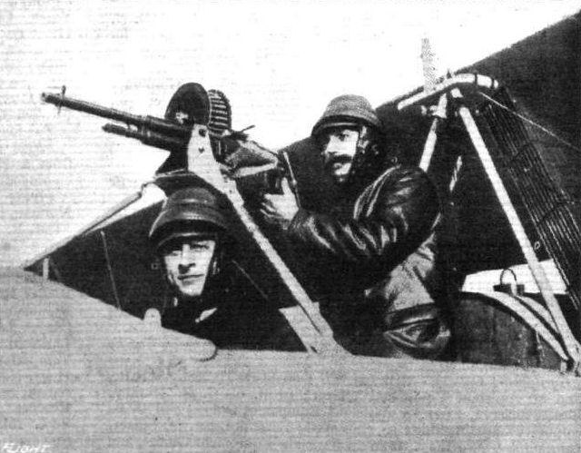
Photograph reproduced from Flugsport showing how the Hotchkiss gun is mounted above the head of the pilot in the Voisin biplane.
A Unique Atterrissage. - A Bleriot come to rest on the upper wing of a Voisin biplane. The occupants of both machines were none the worse for this little incident.
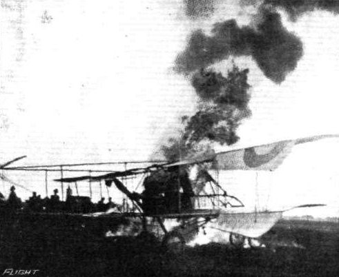
A French Voisin brought down by the Germans in Breisgau. The French officers managed to set fire to the machine before being captured.

TROPHIES OF WAR. - 4. Nacelle of a captured French Voisin biplane.
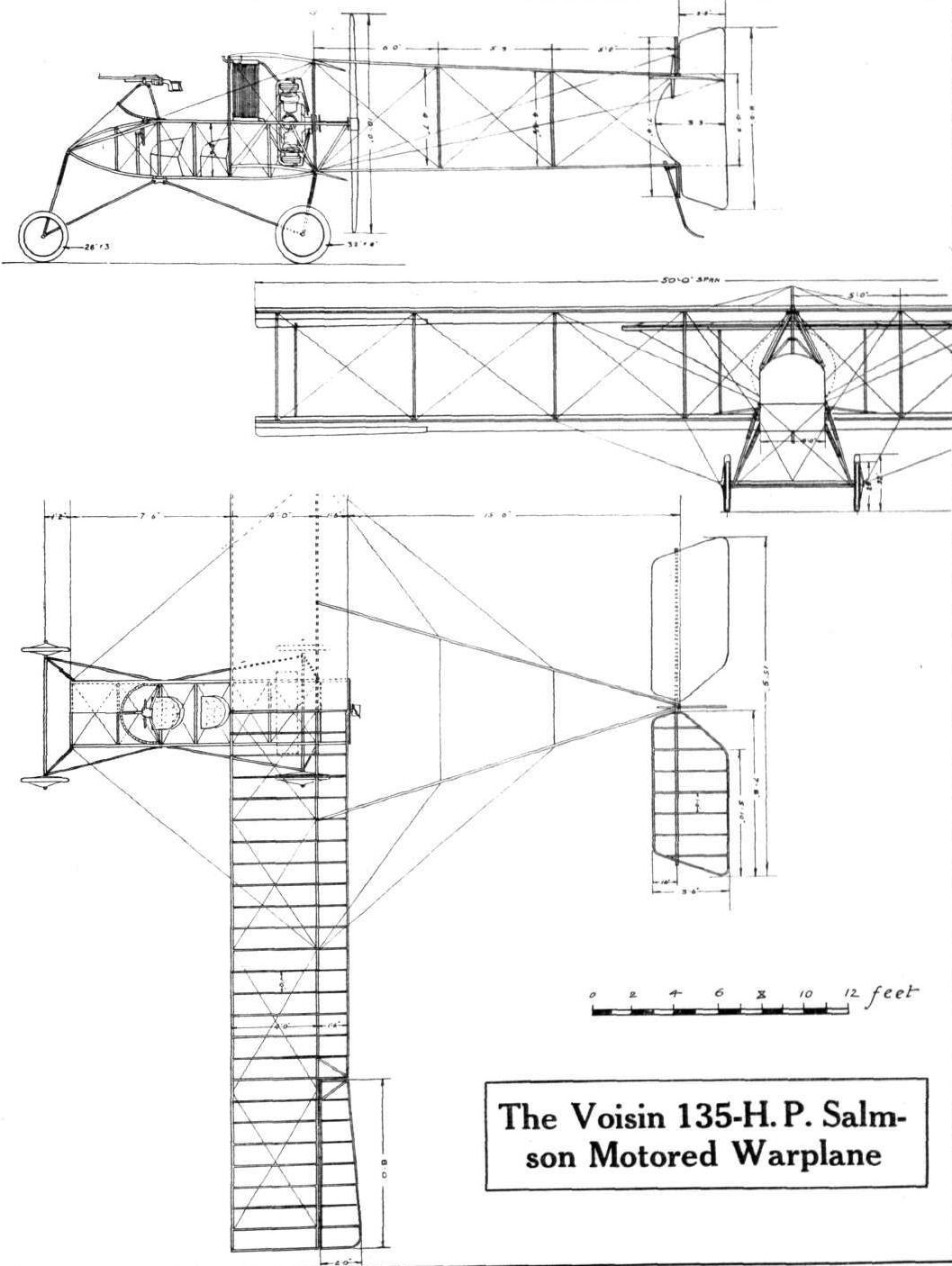
THE VOISIN BIPLANE. - Plan, side and front elevation to scale.