Журнал Flight
Flight, October 4, 1917.
FROM OTHER LANDS.
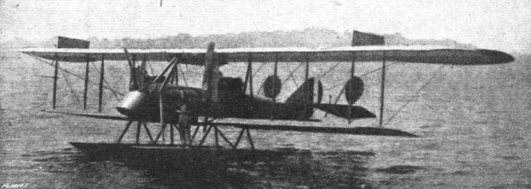
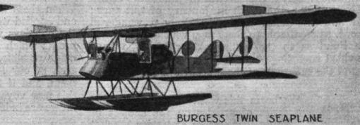
BURGESS TWIN-MOTORED HYDRO-AEROPLANE.
TRIALS are now under way to list for official purposes the performance results of the twin-motored hydro which has just been completed at the Marblehead factory. The design takes in consideration the advantage of locating a machinegun operator forward of the planes and propellers. The machine, besides being equipped with the usual complement of instruments, has the Sperry gyroscopic stabiliser and other improved installations.
General Dimensions.
Span, upper plane 72 ft. 0 ins.
Span, lower plane 51 ft. 9 ins.
Chord, both planes 7 ft. 7 ins.
Gap between planes 6 ft. 11 ins.
Length over all 32 ft. 5 ins.
Height over all 13 ft. 3 ins.
Gross weight 5,380 lbs.
Motors (2) Sturtevant 5A, each 150 h.p.
Gliding angle 8 1/2 to 1
Climb in 10 minutes 3,500 ft.
Speed range, loaded 78-45 m.p.h.
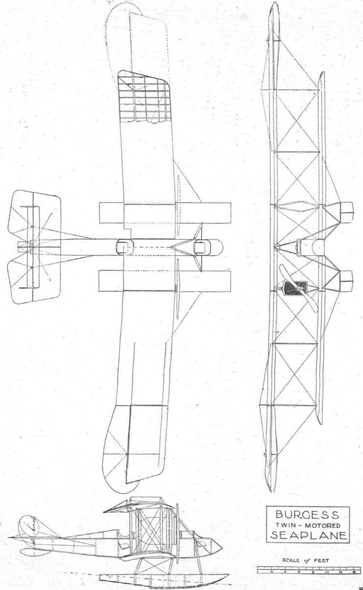
Planes. - Upper plane is in five sections - the flat centre section 12 ft. 6 ins. wide; the outer sections each 16 ft. 8 ins. wide; and the overhanging sections 11 ft. 4 ins. wide. The ends of the ailerons project beyond the wing tips at either side for a distance of 1 ft. 6 ins.
Ailerons on the upper plane are 12 ft. 10 ins. in length, minimum with 2 ft. 1 in., maximum width 3 ft. 5 ins. A small balancing portion beyond the wing tips extends forward of the rear main wing beam. Control arms are located 7 ft. from the inner end of aileron.
With the exception of the centre sections, the planes are swept back at an angle of 3°. On the lower plane, this angle corresponds to a distance of 10 3/4 ins. that the straight portion of the leading edge recedes from a straight line at right angles to the fuselage centre.
Dihedral angle, centre section, upper plane, 180. Dihedral angle of other wing sections 178 degrees.
Upper and lower planes are set at a 30 incidence angle, equal to rise in the leading edges of 4 15/16 ins. The transverse and lateral centre of gravity is located 2 ft. 11 ins. from the leading edge, at which point a hoisting eye is located.
Centres of wing beams are located as follows: Front beam 9 1/4 ins. from leading edge; beams 4 ft. 6 ins. apart; trailing edge 2 ft. 3 7/8 ins. from centre of rear beam. Wing chord, 7 ft. 7 3/8 ins.
Fuselage. - The fuselage is 27 ft. 6 1/2 ins. long; maximum width, 2 ft. 4 ins. Maximum depth between longerons, 2 ft. 11 ins. The nose extends 6 ft. 11 ins. forward of the main planes. The observer's cockpit is located at the nose, and the pilot is located immediately below the trailing edge of the upper plane.
Location of vertical fuselage members are indicated by dotted lines on the drawing. The fuselage termination is 18 ins. high, formed by a strut which carries the central rudder and also supports the tail float.
Tail Group. - Horizontal stabiliser, 16 ft. across at the trailing edge. Width, 4 ft. 0 1/2 in. The leading edge is straight for a distance of 13 ft. 4 ins,, then curved in a 9 ins. radius to a raked angle. It is non-lifting. Elevators are 16 ft. 8 1/2 ins. from tip to tip. Maximum width, 3 ft. 8 ins. Control posts located 6 ft. apart, one on each flap.
The vertical fin is 3 ft. 2 ins. high, and to it the central unbalanced rudder is hinged. The central rudder is 2 ft. 3 ins. wide.
In addition to the central rudder, there are a pair of balanced rudders located 6 ft. to either side of the fin. These rudders have a maximum height of 3 ft. 2 ins. and a width of 2 ft. 2 ins.
Floats. - Floats are arranged catamaran style, with centres 10 ft. apart. Each float 3 ft. Wide, 19 ft. 1 1/2 ins. long and 2 ft. in overall depth. A step 3 3/4 ins. deep is located 11 ft. 10 1/2 ins. from the front end. Struts to the fuselage are located at the following distances from the nose: 4 ft. 3 ins.; 4 ft. 9 ins.; 5 ft. The dotted and dashed line indicates the water line with the machine fully loaded with a Weight of 5,380 lbs.
The tail float is 19 ins. wide, 4 ft. 8 ins. long and 11 3/4 ins. deep.
Motor Group. - Motor carrying struts are located 11 ft. 7 3/4 ins. apart. The drawing shows the motors covered in with metal cowling. Propellers are 8 ft. 10 ins. in diameter, rotating in opposite directions.
The motors are Sturtevant model 5 A, rated at 150 h.p. These motors are 8-cylinder, 4-stroke cycle, water cooled, with a 4-inch bore and 5i-inch stroke. The normal operating speed of the crankshaft is 2,000 r.p.m., and the propeller shaft is driven through reducing gears. The weight per h.p. of the motor is 3.4 lbs.
Fuel is consumed at the rate of 26 gallons per hour, and tanks have a capacity sufficient for an eight-hour flight. - (Aerial Age, U.S.A.)