W.Green, G.Swanborough The Complete Book of Fighters
BURGESS (HT-B) HT-2 USA
In the late autumn of 1916, the US Navy framed a requirement which, issued on 17 November, called for a float-equipped single-seat fighting scout with a max speed of at least 95 mph (153 km/h) and an endurance of 2.5 hrs. It was envisaged that a 165 hp Gnome Monosoupape 9N rotary engine would be used. To meet this requirement, W Starling Burgess of the Burgess Company of Marblehead, Mass, a division of the Curtiss Aeroplane and Motor Corporation, produced the HT-B which was demonstrated to the Navy Department on 19 May 1917. A fabric-covered wooden sesquiplane in which close attention had been paid to aerodynamic cleanliness, the HT-B had fabric-covered K-type interplane struts, the short floats embodying shock absorbers. The intended armament comprised a single 0.3-in (7,62-mm) machine gun, but the rotary engine being unavailable, the HT-B was fitted with a water-cooled Curtiss OXX-2 of 100 hp. With this it was underpowered, max attainable speed being 85 mph (137 km/h). Nevertheless, the Navy considered the HT-B to possess excellent aerodynamic and hydrodynamic qualities, placing a contract for six examples (later amended to include two additional aircraft). Known unofficially as the Speed Scout, the first HT-B was delivered to Squantum on 11 September 1917, and the second to Pensacola in the following month, neither carrying armament. These were followed by six more of a slightly modified version known as the HT-2, all being delivered by the end of 1917. No details of the subsequent career in US Navy service of the HT-B are available, but this is understood to have been brief and did not long survive the demise of the Burgess Company in November 1918.
Max speed, 85 mph (137 km/h) at 1,000 ft (305 m).
Endurance, 2. 0 hrs.
Span, 34 ft 4 in (10,46 m).
Length, 22 ft 3 in (6,87 m).
Height, 10 ft 9 in (3,28 m).
Журнал Flight
Flight, September 27, 1917.
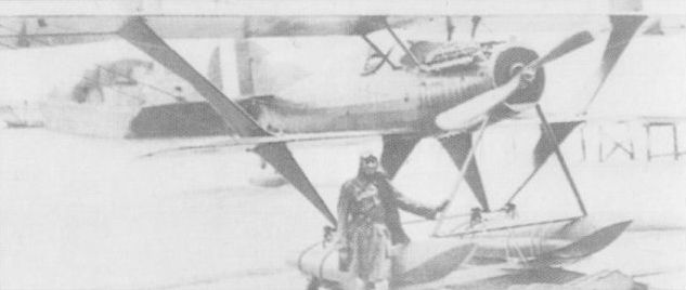
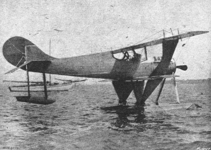
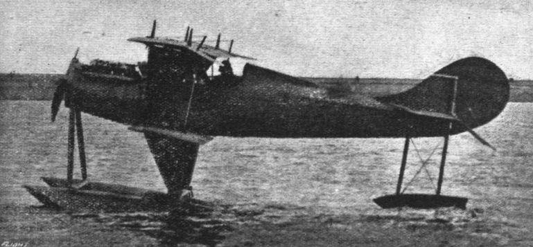
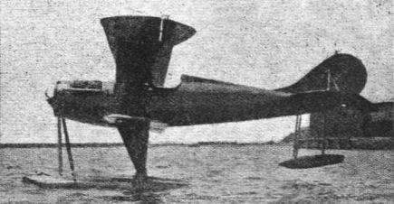
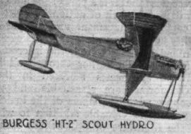
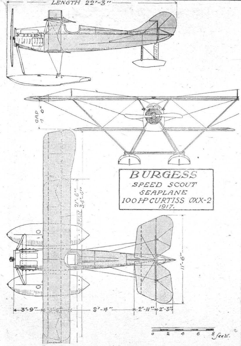
THE BURGESS SPEED SCOUT SEAPLANE.
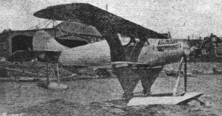
AN interesting type of seaplane has recently been constructed, and tried out, by the Burgess Co., of Marblehead, Mass., U.S.A., namely, the HT-2 speed scout. A short while back we gave an illustration of this machine, and this week we are able to give further particulars and scale drawings, for which we are indebted to our American contemporary, Aerial Age. A number of original constructional features have been incorporated in this machine, the most noteworthy of which are the interplane struts, float struts, and the shock absorbing attachment of the floats.
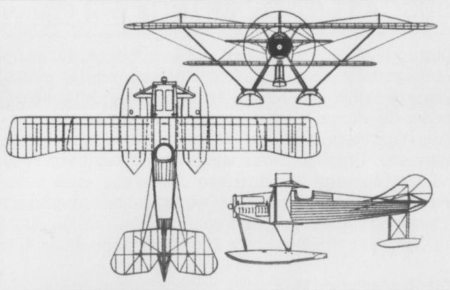
Numerous test flights were carried out by W. E. Doherty this summer with the object of discovering if the original design could be improved upon. One or two modifications thus suggested may be found on referring to the scale drawings, viz., vertical surfaces on each pair of king posts on the top plane, the elimination of bracing wires on the ailerons, the cutting away of a portion of the top plane above the pilot's seat, and the mounting of the tail float nearer to the fuselage. Wherever possible, sharp angles have been eliminated, also, by means of balsa-wood streamlining.
The main planes are comparatively narrow in chord, and have neither stagger, sweep-back, nor dihedral. The upper plane is in four sections, the inner sections being joined in the centre by a pair of metal plates at the wing spars. Each of these sections measures 11 feet span, whilst the outer or overhanging sections, to which the ailerons are hinged, measure 5 ft. 10 ins. The two lower plane sections extend 9 ft. 4 ins. at either side of the fuselage, which is 2 ft. 6 ins. wide at this point. The front spars are located 8 ins. from the leading edge, and 1 ft. 8 ins. from the rear spar. Ribs are spaced 9 ins. apart. Internal drift wires are terminated to the ends of tapered compression struts which relieve the ribs of compression strains. The overhang, and the interplane brace wires are doubled, the space between each wire being filled with spruce streamlining strips, the edges of which are routed out to receive the wires.
The interplane struts are of spruce, built up to form a K-shape unit, covered with fabric. There is one of these K-units on each side of the fuselage, but instead of being vertical they slope inwards from the top plane. In continuation of each of these struts is a pair of V struts extending to the floats, another similar pair being carried up from each float to the body, the whole system of struts thus forming a W when viewed from the front. The K-unit is built up as follows: One spruce member runs from the upper rear spar to the lower front spar, a second member runs from the lower rear spar to the top front spar, whilst a third member connects the upper and lower spars, giving the K shape. The junctions with the planes are filled into a curve with balsa-wood to give a streamline effect. Two pairs of short struts slope outwards from the fuselage to the top plane.
The fuselage is of good streamline shape, being circular in front, tapering to a vertical knife-edge at the rear. The forward part near the engine is covered with louvred sheet aluminium. The sides and top are curved beyond the longerons by means of thin horizontal spruce stringers supported on formers, and covered with fabric. The top of the fuselage is in sections, which are separately removable, and a semi-elliptical streamlining ridge is fitted, starting from the pilot's head rest.
The pilot's cockpit is exceptionally deep and roomy, and the top of the cockpit, above the instruments, is formed with celluloid, providing ample lighting to the interior, at the same time serving as a wind shield. Deperdussin control is installed, and the aileron control passes through the sides of the fuselage at a point 1 ft. above the lower plane in line with the forward edge of the K struts, and runs to the top of the latter, thence to a pulley, attached to the underside of the upper wing spar, to the aileron crank. Control wire openings in the fuselage are protected by heavy skin washers sewn to the fabric.
The tail planes consist of a horizontal stabilising surface, a vertical fin, rudder, and elevators. The latter are hinged to a common spar and work in unison. The root of the vertical fin is built into the curved fuselage top, and the rudder has a small balancing surface forward of the hinge; the lines of the rudder continue in the same curve of the fin. Solid wire braces run from both the forward and rear spars of the stabiliser to the top of the rudder post; and also from underneath the forward spar to the tail float.
Two main floats, 11 ft. long, 3 ft. beam, and 1 ft. 5 ins. maximum depth. They are spaced 6 ft. 6 ins. from centre to centre, and are connected by two horizontal struts. The forward horizontal strut is located 2 ft. 2 ins. from the bow, and the rear strut, which acts as a shock absorbing axle, 5 ft. behind it. A single strut on each float runs from the horizontal strut to a point on the fuselage near the radiator. The rear "axle" is mounted on the V struts - which are covered in with fabric - extending from the fuselage and lower plane. This "axle" is attached to the floats by rubber chord, in metal guides which allow a vertical movement. By this means of shock absorbing much of the porpoising when taxying has been eliminated, and many of the hard landings are taken up by it. The floats have a slight V bottom, with a step located 4 ft. from the stern, and turtle-deck tops. A 2-in. air duct passes through the float at the step. The main support for the tail float is provided in a 2 ft. 2 in. extension of the fuselage sternpost, streamlined fore and aft to a width of 7 1/2 ins. A pair of struts, 2 ft. long, support the front end of the float, and bracing wires run from front and rear struts.
A Curtiss OXX-2 100 h.p. 8-cylinder V engine is installed, being totally enclosed by the aluminium cowling. The radiator is mounted in the nose of the fuselage, and is 2 ft. 3 ins. diameter. The tractor screw, specially designed for the machine by the Burgess Co., is 7 ft. 9 ins. diameter by 5 ft. 9 ins. pitch.
The principal dimensions of the Burgess HT-2 are :- Span, top 34 ft. 4 ins., bottom 21 ft. 6 ins.; chord, 3 ft. 6 ins.; gap, 4 ft.; overall length, 22 ft. 3 ins.; overall height, 10 ft.; speed range, 50-95 m.p.h.