M.Goodall, A.Tagg British Aircraft before the Great War (Schiffer)
Deleted by request of (c)Schiffer Publishing
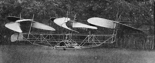
MUMFORD helicopter SO.60,1st and 2nd versions. (Edwin R. Mumford and J. Pollock Brown, Denny Bros., Leven Shipyard, Dumbarton, Strathclyde)
The partners were two senior men running the test tank at the shipyard, and the project was sponsored by Mr. Maurice Denny in 1905. A great deal of experimental work was carried out, and the first machine was virtually complete in 1906, but by 1909 was still in difficulties with the unsatisfactory Buchet engine, which was not achieving its claimed 25hp. This was replaced that year with a four-cylinder inline NEC, which also proved to be inadequate.
A second NEC, this time the new four-cylinder vee was fitted and first tests took place during September 1911. Thereafter this engine was used in both of the machines that were built.
The two versions were of the same basic layout, but varied mainly in improved detail construction, better materials and general points arising from the tests.
The frame was of rectangular planform, initially made of 1 1/2in o/d and 2in o/d by 22 swg aluminum tube, joined by steel castings and braced by wires. Two long wooden skids were fitted below the outside longitudinal members. The pilot sat behind the engine in the center of the craft with an elevator above him and a rudder at the rear of the frame.
Six 25ft diameter rotors, with two blades each, positioned at the four extremities and at either side at the center, were mounted on shafts tilted forward at ten degrees from the vertical, thus providing forward thrust. In October 1906 the blades were formed of bamboo rims with silk covering, but these suffered from water soakage causing reduction in strength and increase in weight. Steel rims were tried, but elm rims proved to be the most satisfactory and these survived from 1909 to the completion of the trials. In all positions the blades were braced back to their center shafts. The rotors were designed to revolve at 40 rpm.
A gearbox coupled through a clutch to the engine had two output shafts carrying sprockets, running at 3:1 reduction, and drove by chain two lengthwise side drive shafts, from which bevel gearing translated the drive to the rotor shafts. The radiator was made in four sections, which were mounted high up in the frame behind the pilot.
In 1912 the helicopter had made a number of tethered flights to about 10ft height, which culminated in one on 6 January 1913 when damage occurred, due to failure of a side drive shaft. The strain was telling on the aluminum tubes, and it was evident that a major reconstruction was necessary. A new machine was started in 1913 with a structure made of composite material of paper, wood and cloth, a foretaste of bonded materials of many years ahead.
Late in 1914 the new machine was fitted with floats, in which form it taxied out onto the water and flew 100 yards at 10ft height. The machine was towed back to the slipway, where it was destroyed that night by a gale, which ended this promising experiment.
Power:
25hp Buchet eight-cylinder air-cooled vee. The specified weight of 110 lb was exceeded and the power was not achieved.
25hp NEC four-cylinder inline two liter water-cooled two-stroke, weight 187 lb
40hp NEC four-cylinder 2.4 liter water-cooled two-stroke vee, weight 159 1/2 lb
A speed of 1,100 rpm was required to drive the mechanism and at this speed the first NEC gave less than 23 bhp; the second gave 37 bhp at 1,100 rpm.
Data
Max length 60ft
Max width 41ft
Weight first version originally 886 lb increased to 1,577 lb prepared for flight.
Weight second version 1,508 lb prepared for flight.
P.Lewis British Aircraft 1809-1914 (Putnam)
Mumford Helicopters 1 and 2
In 1906 Edwin H. Mumford and J. Pollock Brown, of Wm. Denny & Brothers, Dumbarton, who were in charge of the firm's experimental tank and had studied the theory of ships' propellers, designed a direct-lift aircraft based on the results of their researches. I t comprised a tubular framework of rectangular plan-form carrying six large two-bladed rotors of 25 ft. diameter and 19 ft. pitch, whose axes were inclined outward and forward at 10° from the vertical. The first rotors were constructed of silk stretched over a framework and braced by wires from a central king-post. The propeller frames were made first in bamboo - which soaked up water and rotted - and then of steel tubes. These, however, were found to be too flexible, but, finally, the elm frames used in 1909 were satisfactory for the purpose. The three rotor shafts on each side were parallel to each other and were driven through bevel gearboxes by a longitudinal shaft, the two side shafts in turn being geared to inclined cross-shafts driven by the centrally-mounted engine. The first engine, a 25 h.p. Buchet, was replaced in 1909 by a four-cylinder two-stroke N.E.C. of 25 h.p., and this in turn gave way in 1911 to a V-4 N.E.C. of 40 h.p. The pilot sat behind the engine, and the control surfaces provided were an elevator above the pilot's head and a vertical rudder at the rear of the machine. The helicopter rested on two long wooden skids. The structure and transmission shafts were of aluminium tubing, and the complete aircraft weighed originally 886 lb. with the pilot. As modifications were made, the weight increased until it reached 1,580 lb. in flying condition.
The gearboxes were of exceptionally efficient design, and very few transmission difficulties arose. Tests were made first with an electric motor on the ground and, in 1912, tethered flights to 10 ft. were achieved successfully with the V-4 engine installation, in January, 1913, a side shaft broke and caused two adjacent rotors to foul, with the conseqent wrecking of the machine.
Experiments were resumed in 1914, when a second helicopter of generally similar design, but with much detail improvement, was built in Denny's Leven yard. This version was more compact and of stiffer construction and was mounted on long parallel floats. The same power unit and transmission as before were used, but the aluminium struts were replaced by composite tubes manufactured from paper, wood and fabric. In this form the machine weighed 1,508 lb. empty. In the autumn of 1914 it was launched on the River Clyde and made a successful flight of 300 ft. at a height of 10 ft., during which it lifted a total weight of 1,600 lb. and achieved a forward speed of about J 5 knots. It was then returned to the slipway because of an approaching gale, by which it was wrecked completely later that night. War had already broken out, and it was not possible to undertake any further helicopter experiments.