M.Goodall, A.Tagg British Aircraft before the Great War (Schiffer)
Deleted by request of (c)Schiffer Publishing
CLARKE-WRIGHT glider
This biplane glider was ordered by Alec Ogilvie and his partner, T.P. Seawright, in order to obtain practice before delivery of a Short-Wright biplane. Delivery took place in August 1909, after only four weeks under construction and gliding took place at Camber Sands thereafter. The design was based on the Wright No.3 glider, but with a biplane front elevator with fixed fin and upright seating. Launching was by weight and pylon as with the Wright machine. A glide of 343 yards was the most achieved.
Data
Span 32ft 8in
Area 318 sq ft
Length 18ft
OGILVIE & SEAWRIGHT glider (Alec Ogilvie and T.P. Seawright, Finchley, London)
A quadruplane glider was constructed in 1908 by the partners. It was fitted with a four wheeled undercarriage and was towed behind a car. It apparently came to grief when the tow rope broke, when the machine was at a height of thirty feet, piloted by Ogilvie's brother.
The following year Ogilvie bought a Wright type glider from T. W.K. Clarke and a Wright aircraft from Short Brothers.
P.Lewis British Aircraft 1809-1914 (Putnam)
Clarke-Wright Glider
To enable Alec Ogilvie to obtain some practice before taking delivery of the Short-Wright Biplane which was being built for him by Short Brothers, in partnership with T. P. Searight he ordered a Wright-type glider from T. W. K. Clarke and Company of Kingston-on-Thames, Surrey.
The machine was based on the Wright No. 3 Glider, but was fitted with a biplane elevator in front and with a seat to enable the pilot to sit upright. The two-bay wings were double-surfaced and had an aspect-ratio of 6.5. Controls consisted of warping wings, the front elevator and the rear rudder; a fixed fin was incorporated between the elevator surfaces.
The glider took four weeks to construct and was completed at the end of August, 1909. Launching was by means of a weight and derrick, and many fine flights were made on the South Coast at Eastbourne, the longest distance covered by Ogilvie being 343 yards.
SPECIFICATION
Description: Single-seat biplane glider. Wooden structure, fabric covered.
Manufacturers: T. W. K. Clarke and Co., 14 Union Street, Kingston-on-Thames, Surrey.
Dimensions: Span, 32 ft. 8 ins. Length, 18 ft. Wing area, 318 sq. ft.
Журнал Flight
Flight, September 18, 1909
THE WRIGHT GLIDER AS MADE BY CLARKE.
GLIDING is a side of flight that is a little apt to be neglected in the present rush to achieve the higher art; but it is a useful side nevertheless, and the present is a particularly appropriate time to learn the mastery of the motorless flyer, seeing there is for the moment some difficulty about obtaining a proper supply of engines in this country. Other experimenters have, it is true, shown that the stepping-stone used by the Brothers Wright is not necessary in all cases; but, all the same, we are not at all sure that gliding may not teach a lot even to the flying man, and in any case it seems to us that Messrs. Alec Ogilvie and Searight have done very much the right thing in having a glider built for them in addition to the Wright flyer which they have on order. At the least it may be the means of saving the flyer from some little unnecessary damage during the early stages of learning to fly.
The glider which Messrs. Ogilvie and Searight have had built for them is to all intents and purposes a copy of the machine used by the Wrights in 1902, and the work has been admirably executed by Messrs. T. W. K. Clarke and Co., of Kingston. It is of course a biplane, and has an elevator in front with a vertical tail behind. The elevator, however, is constructed according to the design shown in the latest Wright patent - with which our readers are acquainted - having flexing planes instead of simple pivoted planes. The tail at the rear consists of a single vertical plane, in which respect it is in agreement with the Wright glider, but differs from the Wright flyer, which has a double rudder. On the other hand the main decks are double surfaced on the machine which Messrs. Clarke have constructed, whereas the gliders used by the Wright Brothers were, we believe, invariably only single surfaced. The workmanship which Messrs. Clarke have put into the construction of the glider is admirable, and thoroughly upholds British reputation for making a sound job. There are some people who rather incline to the view that a machine which is going to be knocked about need not have much time spent upon its construction in the first instance, but for our own part we favour the other aspect of the case for the two points which it has in its favour, the first being that the better a machine is made the less liable is it to give trouble any way, and the second being that when it does get smashed a well-made article is always more easily and satisfactorily repaired than one which is half a wreck to start with. Moreover, there is always the consideration that a certain amount of risk attaches to flight, which it is gratuitous to exaggerate by neglecting any reasonable proportions such as using a decently built machine to fly on, and although, of course, a well-made glider will probably cost more than one on which less care has been spent, there is no reason why the old adage should not apply, "the best is cheapest in the long run."
Timber and Fabric.
The material from which Messrs. Clarke have constructed the glider is for the most part silver spruce, a timber which, we understand, they are able to procure in 20 ft. lengths without a flaw. In one or two places where bent woodwork is required - as, for instance, the extension of the runners which carry the elevator, and the extremities of the main decks - American elm is used. The decks are double-surfaced with a special fabric of British make, which Messrs. T. W. K. Clarl.e supply; it has a weight of 36 sq. ft. to the lb., and the waterproofing is done by a celluloid treatment. The seams in the complete covering are diagonal, and each half of a deck, from an extremity to the centre, is practically enclosed with a kind of fabric bag, the edges of adjacent bags are laced together in the centre, while at intervals the fabric is tacked down to the supporting ribs. In order to prevent the fabric being torn, a thin strip of wood is placed between the fabric and the heads of the nails.
Main Decks.
The skeleton framework on which the surfaces are stretched consists, for each deck, of a pair of transverse spars having a section 1 in. deep by 11 ins. At the extremities these spruce spars are joined together by a piece of bent elm, a scafe joint being made between the two timbers.
At intervals of 1 ft., light ribs pass fore and aft between the spars and overlap the rear spar to give a flexible trailing edge extending rearwards about 15 ins. The ribs consist of two small strips of rectangular section wood separated by distance pieces at intervals. Each rib as it is built up is curved to a template so as to give a camber to the decks of 3 ins. at the maximum versine. The method of fastening the ribs to the front spar, which by the way is rounded off to form a blunt cutting edge, is to secure the last distance piece to the spar by screws so that it virtually belongs to that member and, as it were, forms a supporting tongue for the top and bottom members of the rib proper. The connection is then further strengthened by putting a light strap of metal round the spar and tacking the ends to the rib.
Considered as a unit, the framework of the two decks, taken together, forms an example of the usual lattice girder work which has been commonly adopted on biplanes. In accordance with the Wright system, the machine built by Messrs. Clarke further belongs to the flexible type, that is to say, non-rigid joints are employed as fastenings between the main spars and the struts which separate them.
These joints are carried out somewhat after the manner devised by the Wrights, but Mr. Clarke has substituted a steel plate for the wire eye used in the Wright machine. The struts have a saw-cut taken down their extremities for an inch or so, and into this is let the steel plate which is pegged and bound in place. The projecting end of the steel is drilled to receive a hook, which in this case consists of a steel U-bolt which passes through the main spar and is secured on both sides by nuts. The same steel plate also provides an anchorage for the wire ties.
(To be concluded.)
Flight, September 25, 1909
THE WRIGHT GLIDER AS MADE BY CLARKE.
(Concluded from page 571)
Elevator and Tail.
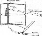
THE elevator is, as has already been mentioned, constructed according to the latest Wright patent, that is to say, the two planes are so mounted that they flex or warp, instead of merely pivot when a change is made in their angle of incidence by the operation of the elevating lever. In order to accomplish this warping the two decks of the elevator are mounted in rather a peculiar way, the framework of each being built up upon a single transverse-spar situated about 9 ins. from the leading edge; the full cord of the elevator is 2 ft. 6 ins. There is thus a flexible leading edge as well as a flexible trailing edge, the relative flexibilities being more or less in proportion to the overhang of the main spar. The main spar itself is pivoted to the uprights which support it in order to avoid twisting strains when the decks are flexed; it is evident that although the action of the elevator mainly consists of a warping action of the decks, a certain amount of pivoting must necessarily occur simultaneously.
The operating mechanism for flexing the elevator decks consists of three stiff ribs, which lie fore and aft, midway between the two decks of the elevator. These members are fixed to a transverse tubular spar, which is pivoted to a bracket projecting from the same upright as supports the spars of the elevator decks; it is, however, situated some few inches forward of their axes. From the extremities of each operating rib two struts pass to the leading and trailing edges of the upper and lower decks respectively, and it is by means of these struts that the elevating decks are warped. The operation of manipulating the elevator is performed by rocking the tubular transverse spar upon which the operating ribs are mounted, and the fact that this spar is pivoted about a different centre to that on which the elevator decks are supported, causes a difference in the relative amount of travel imparted to the leading and trailing edges.
The result of this is that instead of the elevator decks remaining fiat as they tilt or dip, their surfaces become cambered, and according as the front edge is dipped or tilted so is the camber convex or concave to the ground. The object of this system is to increase the efficiency of the elevator by converting the decks, which are normally aeroplanes, into cambered aerofoils directly they are required for use. As the elevator has to work both ways, it is necessary to make provision for cambering in both directions, hence the adoption of the device for mechanically warping the decks in the manner described. For the purpose of rocking the tubular spar to which reference has already been made, a simple lever and connecting-rod are employed, the connecting-rod in this particular case being built up so as to have a hollow rectangular section in order to give greater stiffness.
Between the elevator decks is a semi-circular vertical plane forming a prow.
The tail, which is controlled by another lever, consists of a simple plane mounted vertically between two outrigger spars. These spars are hinged to the rear transverse spars of the main decks so that they shall not be readily broken if the tail strikes the ground. In order that this hinging may be effective, that diagonal tie-wire which would ordinarily be stretched as the result of any such deformation, is fitted with a length of strong elastic. The elastic is sufficiently strong to keep the outrigger in its proper position under normal conditions.
The Chassis and Pilot's Seat.
The machine as a whole is mounted upon two runners which commence a short distance behind the main decks and extend forward with a gradual curve which is ultimately increased in a sharp bend where they join on the upright supports for the elevator. The runners are stayed to the front spar of the upper main deck by a set of oblique struts. The lower deck is supported a little above the rudders by a lattice work bracing.
The pilot is accommodated in an extremely light but fairly comfortable chair - in which respect the machine differs from the original Wright gliders, where the operator took the air lying prone on the lower deck.
The Wright Control.
On each side of the pilot is a vertical lever. That on the left moves to and fro only, and works the elevator in manner already described. That on the right can move either to and fro or sideways, that is to say, in reality it has a kind of universal motion. The two and fro movement works the rudder, and the sideways motion warps the main decks. This warping of the main decks is carried out by means of wires, which pass through short lengths of Bowden tube, this method of guiding them being considered by Mr. Clarke to be far superior to the use of pulleys. It may here be mentioned, while on the subject of wire bracing, that the main wire diagonals are not fitted with any tightening device, being merely drawn hand-tight, and fastened by simple brass bands, the ends of the wire being turned back over the bands to prevent them from slipping.
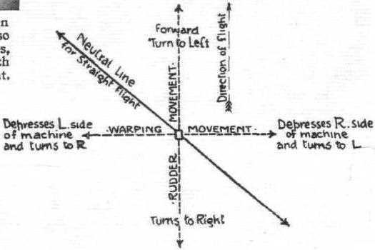
The lateral control of a Wright glider, or flying machine, by a single lever which warps the wings and moves the rudder, is the most interesting and characteristic feature of the Wright system, but its action is apt to be a little difficult to grasp unless each movement is taken in sequence. The lever on the machine built by Messrs. Clarke is situated on the pilot's right; it normally stands in a vertical position when the machine moves straight ahead on an even keel. The connections are such that -
(1) If the lever is moved forward, the rudder puts the prow to the left.
(2) If the lever is moved to the right, the left hand extremities of the main decks have their rear edges warped downwards so as to increase the angle of incidence.
The next point to take into consideration is the primary result which accompanies each of the above movements made independently.
(1) From steering to the left, the increased relative velocity of the right wing tip will cant the machine so that the right wing rises.
(2) The first effect of increasing the angle of incidence of the left-hand extremities of the main decks is to increase the resistance of flight on that side of the machine, which consequently tends to slow up, or in other words tends to put the prow of the machine to the left.
If, on the other hand, the course is kept straight by using the rudder, then the effect of increasing the angle on that side of the machine is to raise the left extremity of the main decks and so cant the machine over while it proceeds straight ahead. This manoeuvre may either be performed for the purpose of restoring equilibrium from an accidentally canted position or to establish a cant artificially for the purpose of banking when taking a sharp turn.
It will be observed from the foregoing brief description that the to and fro and sideways movements of the lever have results which are closely related to one another and from which it is a simple matter to deduce that -
(1) If it is desired to restore equilibrium from an accidental cant which has depressed the right hand extremity of the main decks, then the lever must be drawn towards the pilot - i.e., to the left - in order to increase the angle of incidence of the right hand extremities of the main decks which it is desired to lift and at the same time the lever must be pushed forward so as to steer to the left in order that the initial effect of warping described above shall not turn the machine from its straight course.
The result of making, or rather trying to make, simultaneous movements of the lever along axes at right angles to each other is to follow a diagonal path ; from this fact may be deduced the following very important fact: -
(1) Equilibrium and a straight course with the Wright flyer are maintained by a diagonal movement of the lever, in which
(a) It is moved obliquely forward and towards the pilot, in order to rectify an accidental canting of the right-hand extremities of the main decks downwards, or
(b) The lever is moved obliquely backwards away from the pilot, in order to check a cant which has depressed the left wing.
This oblique neutral line, represented in one of our diagrams, is the normal path of travel for the pilot's right hand, while he keeps the machine on a straight course. Any movement of the hand away from this line must result in a curved course, because the rudder or the warping effect preponderates.
The precise nature of the movement which the pilot would perform in order to steer, say, to the left depends on the manner in which he wishes is to carry out the operation, which in turn is governed by the sharpness of the curve, his speed of flight and other considerations. In general, however, it may be said that the pilot's hand for such a manoeuvre moves through an oval path starting and finishing in the neutral vertical position; this oval path is the result of a perfectly performed sequence of very short straight movements each of which has resulting in a combination of warping and rudder action. Needless to say, such perfection is not immediately within reach of the novice, the movements of whose hand would be more than likely to show up the straight line components of the curve.
It should perhaps be mentioned here that the reason why the rudder and the warping of the planes has to take place simultaneously is primarily due to the fact that the Wrights warp the main decks of the machine instead of employing independent balancing planes. When the main decks of a glider or flyer are warped it is not easy, even if it is possible, to warp one extremity up and the other extremity down to an equal extent considered from the point of view of effectiveness. To all intents and purposes only that extremity which has its trailing edge warped downwards need be taken into consideration, because while that undoubtedly does exert a powerful lift, the corresponding warping of the other extremity does not result in an equal amount of depressing action because the resultant curvature of the decks at that end of the machine is such that their angle of incidence is diminished but not effectively reversed. On the one side of the machine, therefore, an active force is in operation, whilst at the other extremity the conditions are rather of the passive order. The resistance of that extremity which has an increased angle of incidence given to it makes itself felt, and there is no corresponding resistance at the opposite end of the flying machine to neutralise the swerving effect which it induces; On the contrary, the resistance there is less than in the normal condition of straight line flight, so that the swerving effect is outside. Hence the need for using the rudder.
A Word of Warning.
Owing to a slight misunderstanding between ourselves and Messrs. Ogilvie and Searight, the foregoing article has been published by us without their prior knowledge. It should, moreover, be clearly understood that this particular glider of theirs was built by them at the express suggestion and with the direct permission of the Wright Brothers, pending the delivery of the full-sized motor-driven Wright machine which Messrs. A. Ogilvie and T. P. Searight have on order with them.
 |
P.Lewis - British Aircraft 1809-1914 /Putnam/
|
| Clarke-Wright Glider.
|
 |
Журнал - Flight за 1909 г.
|
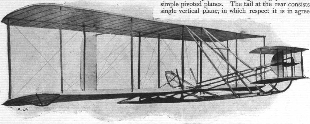
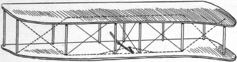
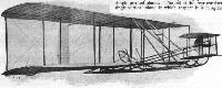
| General view, from in front, of the complete Wright-Clarke glider. Light bow-skids are fitted under the extremities of the lower deck, as shown above.
|
 |
Журнал - Flight за 1909 г.
|
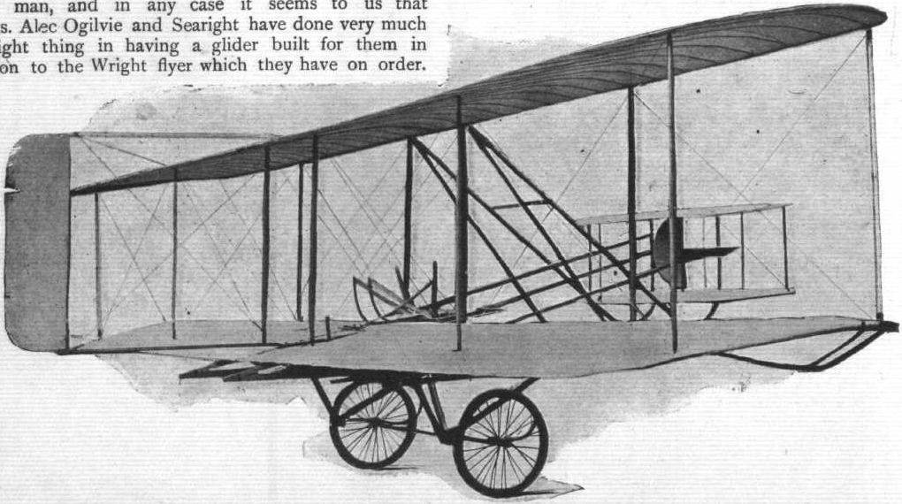
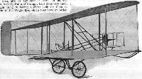
| In this view, as seen from behind, the glider is shown mounted on a specially-designed two-wheeled hand-cart, by means of which the whole machine can be easily wheeled about by one man.
|
 |
Журнал - Flight за 1909 г.
|
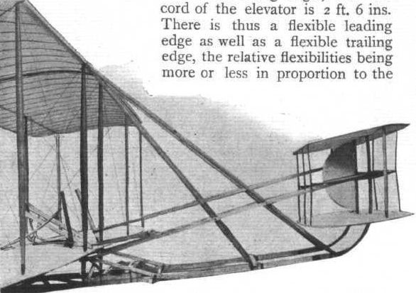
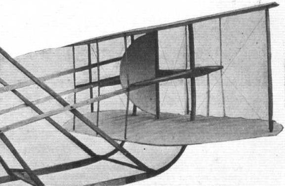
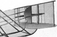
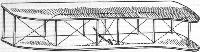
| The outrigger construction and relative position of the elevator are clearly indicated above.
|
 |
Журнал - Flight за 1909 г.
|
| Detailed view of the elevator, showing its attachment to vertical continuations of the runners, and the stationary cutwater or prow of semicircular form situated between the two planes.
|
 |
M.Goodall, A.Tagg - British Aircraft before the Great War /Schiffer/
|
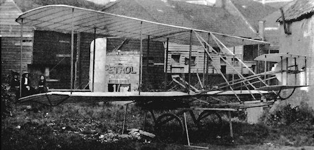
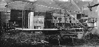
| Ogilvie glider. A modified Wright-type bought from TWK Clarke.
|
 |
Журнал - Flight за 1909 г.
|
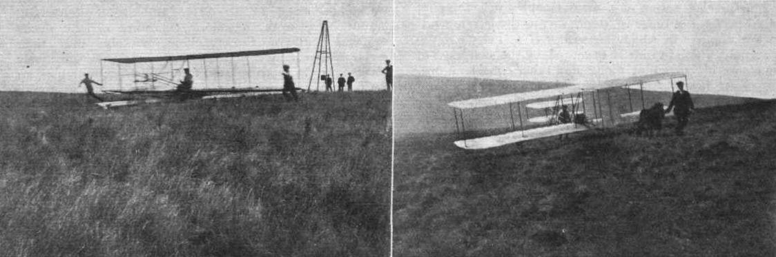
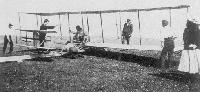
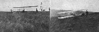
| MR. OGILVIE AT WORK ON THE WRIGHT-CLARKE GLIDER. - On the left Mr. Ogilvie is just rising from the starting rail after the release of the derrick weight seen in the background; and on the right the glider is being, with the help of a Shetland pony, brought back up the practise hill after a glide of some three or four hundred yards.
|
 |
Журнал - Flight за 1909 г.
|
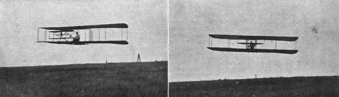
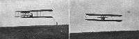
| MR. OGILVIE IN FULL FLIGHT ON HIS NEW GLIDER. - Note the starting derrick in the background, giving a good idea of the distance travelled. On the right the glider is just leaving a 1 in 7 gradient on the hill, and passing over the 1 in 5 gradient, which naturally results in a distinctly increased height above the ground being attained, since otherwise a rapid acceleration of speed would be inevitable.
|
 |
Журнал - Flight за 1909 г.
|
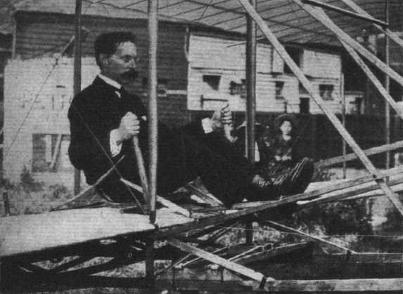
| Mr. T. W. K. Clarke, at whose aero works the glider has been constructed, occupying the aviator's seat. This photograph also shows the two small grooved wheels mounted between the runners, one under the main deck, and the other a little in front, which support the machine on the launching rail preparatory to flight.
|
 |
Журнал - Flight за 1909 г.
|
| Diagrammatic sketch of main planes, showing the arrangement of warping-wires (in dotted line), and the manner in which the rear edges of the planes are flexed. It is important to note that the front or entering edges are unaffected by this movement, remaining always perfectly straight.
|
 |
Журнал - Flight за 1909 г.
|
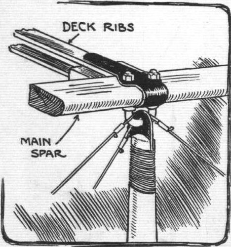
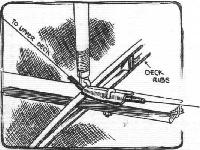
| Sketch of the flexible-joint connecting the vertical struts to the main decks. A slight notch is made at the lower end of the U bolt to keep the eye of the strut central.
|
 |
Журнал - Flight за 1909 г.
|
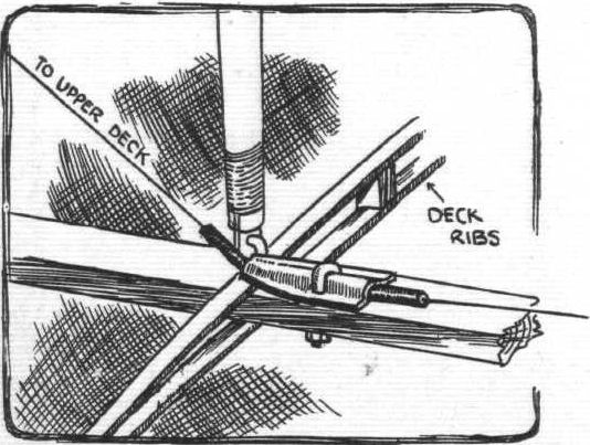
| Instead of pulleys where the warping-wires leave the decks, short lengths of Bowden wire sheath are used clamped to the rear spars, as shown above.
|
 |
Журнал - Flight за 1909 г.
|
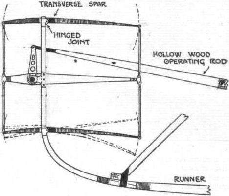
| The Wrights' patent flexing elevator is so arranged that a movement of the operating-rod, besides altering the angle made by the planes with the horizontal, varies their camber or curvature.
|
 |
Журнал - Flight за 1909 г.
|
| The above diagram, of which the small rectangle at the centre represents the right-hand controllever, shows in plan how the two movements capable of being given to this lever result in a third oblique line of movement, along which the aviator's hand passes to and fro to preserve lateral equilibrium during flight.
|
 |
Журнал - Flight за 1909 г.
|
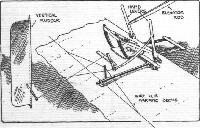
| Central portion of lower deck, showing aviator's seat and the levercontrol system of the glider. It will be observed that the right-hand lever can be moved sideways as well as forwards and backwards.
|
 |
P.Lewis - British Aircraft 1809-1914 /Putnam/
|
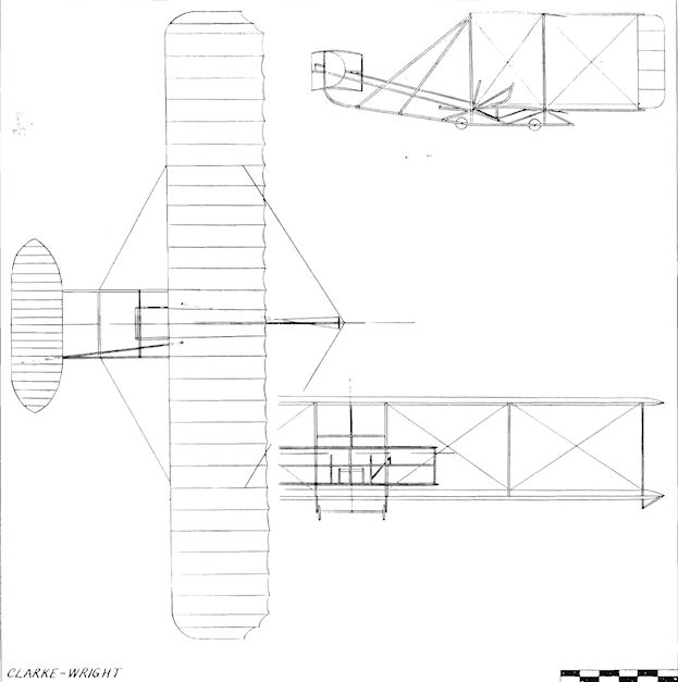
| Clarke-Wright
|
 |
Журнал - Flight за 1909 г.
|
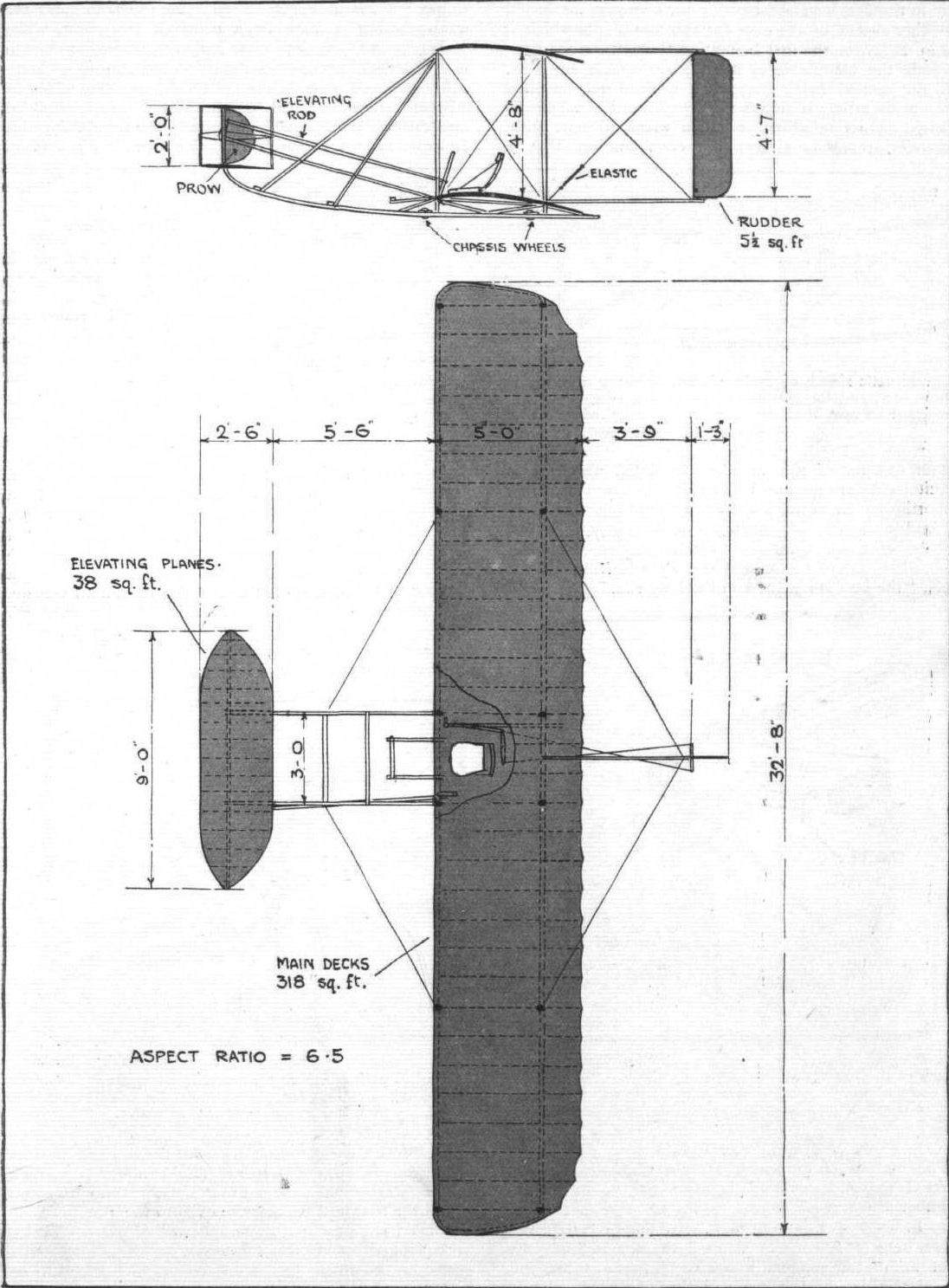
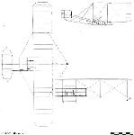
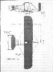
| Plan and Elevation to Scale of the Wright Glider as made by Clarke.
|