C.Andrews Vickers Aircraft since 1908 (Putnam)
<...>
From this 14B and other designs on the same lines it may be concluded that Vickers were thinking in terms of a pusher aeroplane with offensive capability. The linking of their interests in armaments and aviation achieved practical recognition on 19 November, 1912, when a contract was received from the Admiralty for an experimental fighting biplane, armed with a machine-gun.
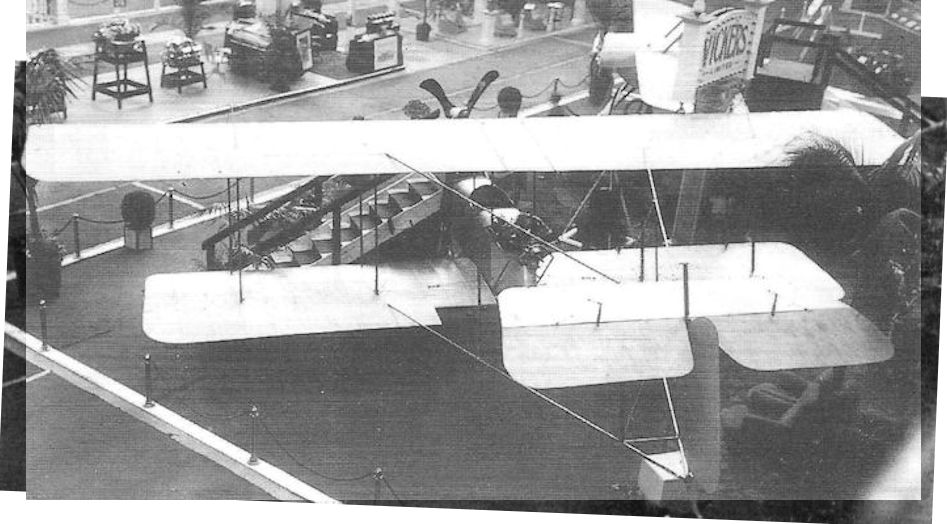
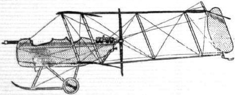
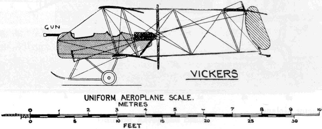
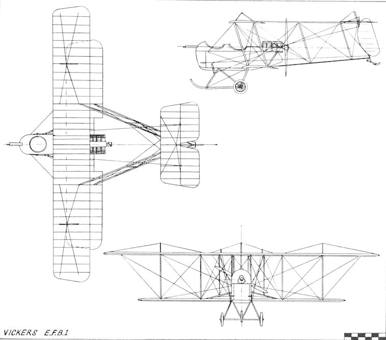
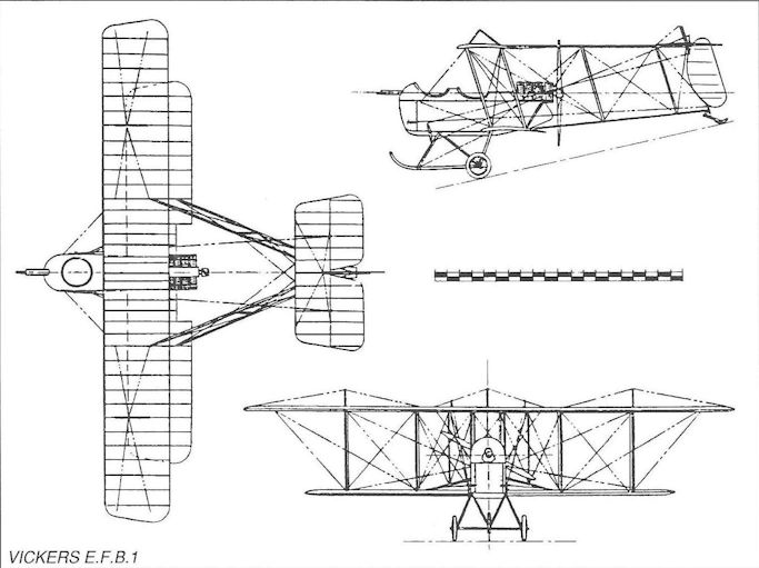
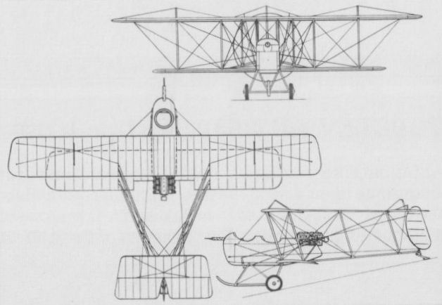
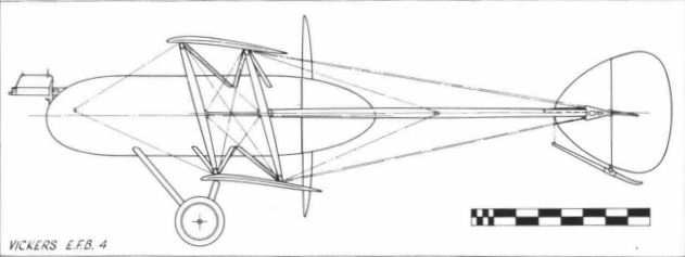
After many layouts had been considered, the Vickers designers decided that the only practical one was the pusher biplane with the gunner located in the nose. This marks the beginning of the era of Vickers military aircraft, for the design was later classified as E.F.B.l (Experimental Fighting Biplane No. 1) and named Destroyer. It was displayed at the Aero Show at Olympia in February 1913, and created great interest as the first gun-carrying aeroplane designed as such. Unfortunately, it crashed on taking-off on its first test flight at Joyce Green. The E.F.B.1 was powered by a 60/80 hp Wolseley eight-cylinder vee engine with water-cooled exhaust valves and air cooling for cylinders and inlets. The curious scimitar-shaped Vickers-Levasseur propeller was fitted.
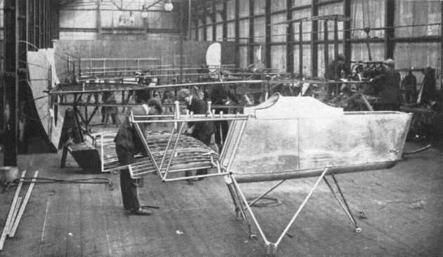
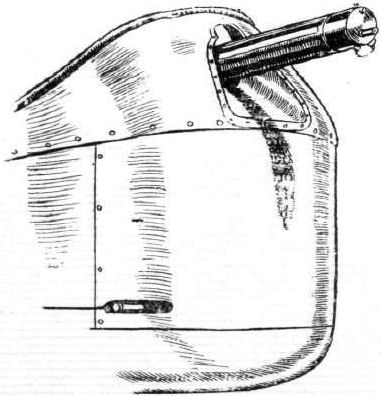
The armament was a movable Vickers gun, lightened and modified so as to dispense with the water-cooling jackets of the infantry type, to give an unobstructed field of fire. The airframe was nearly all metal, the nacelle being of steel tubes covered with duralumin. The wings were staggered and employed warping for lateral control, as was then general practice.
Flight records the appearance of the E.F.B.1 at the Aero Show of 1913 as follows:
'The 60-80 hp Vickers Biplane. A very interesting machine, not only for the fact that, hitherto, the Vickers organisation have confined their attentions exclusively to monoplane construction, but for the great amount of thought and care that, it is evident, has been spent on its construction and design. Standing before this biplane, the first feature that arrests the attention is that there is a Vickers automatic gun protruding from the front of the neatly rounded Duralumin covered body. Then even the lay mind can arrive at the principal reason why the propeller has been placed at the rear of the machine - it is designed to have that position mainly in order to give an unobstructed range of fire in front of the biplane.
'The body of the machine, which extends forwards from the main planes, is constructed in a precisely similar manner to that of the Vickers monoplane'
'In its interior sits the passenger and, behind him, the pilot, both sheltered to a great extent from the wind by the neat metallic covering that is fitted over the body. Seated in front, the observer, and he will have to be a gunner too, has a perfectly clear view all around him. The gun before him is arranged to swivel through an angle of 60° in both horizontal and vertical planes, while the ammunition is stored in a box travelling on wires, beneath his seat. When the gun is not in use the ammunition box is in a position just over the centre of pressure of the planes; when it is required to operate it, the box is wound forward on its wire rails and brought within reach of the gunner. As we have remarked, the pilot sits immediately behind him, and he grips a double-handled vertical lever whereby he controls the machine. Still further behind, the motor is mounted, its lugs bolted to the top two members of the fuselage.
'The planes are made on a system which has little difference from that observed in the building of the Vickers monoplane wings. They are "staggered". Contrary to the more usual plan of using piano wire for the bracing of the planes, stranded steel cable is employed in this machine. As a matter of fact, all the bracing throughout is of stranded cable, excepting the body, where stout wire is used. The planes are so designed that in a very little time they may be dismantled, leaving only a centre section that is no wider than the body itself. Close examination of this central section of the top plane will reveal that in its interior there is a small petrol tank from which fuel is fed to the motor by gravity. It is supplied from a main tank in the body, under pressure, and the tubes leading to and from it are neatly tucked away behind the wooden filling pieces that are used to "streamline" the tubular cellule spars. By the way, the machine does not carry an oil tank, for sufficient oil is stored in the base-chamber of the motor to last for a six hours' flight.
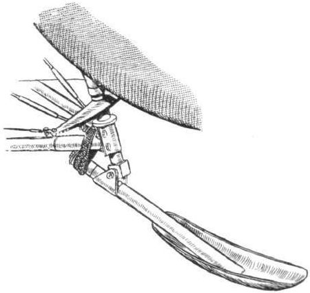
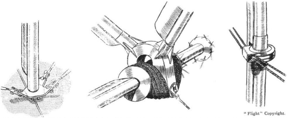
'The landing chassis is, at first sight, very much like that of the monoplane. Its flexible suspension, however, will be found to be altogether different. A central hollow skid of ash is joined to the body by two Vs of steel tubing. Two other Vs of tubing extend downwards and outwards from the side of the body, and, in crutches, at their lower extremities, the axles of the landing wheels travel against the tension of the strong rubber springs. Altogether, the chassis is exceptionally light and compact, and, moreover, looks strong enough to bear any ordinary landing strain that it is likely to be subject to. Differing from the monoplane, too, there is no backward extension of the central landing skid. The weight of the tail is carried by a small steel spoon-shaped tail skid, so fixed that it pivots with the rudder and enables the machine to be steered more or less accurately over the ground at slow speeds.
'The tail, level with the top main plane in flight, is attached to the top of the tubular steel tail outriggers. In plan form it is approximately rectangular, and its interior construction is of steel throughout, tubing being used for its outline, while the cambered ribs are of channel section, acetylene-welded in position.'
<...>
Experimental work was carried out with the Gunbus concept, and the E.F.B.6 was a variant flown in 1914 with extended top wing, presumably to obtain more lift for load carrying, but was not proceeded with. Before that, an advanced project following the general configuration of the E.F.B. 1 Destroyer had been designed under the classification E.F.B.4.
E.F.B.1(Destroyer)
Accommodation: Pilot and gunner
Engine: 80 hp Wolseley
Span: 40 ft
Length: 27 ft 6 in
Height: 11 ft 11 in
Wing Area: 385 sq ft
Empty Weight: 1,760 lb
Gross Weight: 2,660 lb
Max Speed: 70 mph at ground level (est.)
Initial Climb: 450ft/min(est.)
Range: 4 1/2 hr
Armament: One Vickers
M.Goodall, A.Tagg British Aircraft before the Great War (Schiffer)
Deleted by request of (c)Schiffer Publishing
VICKERS EFB.1 (Experimental fighting biplane No.1) Destroyer
This machine, which was the first purpose built armed aircraft, shared the stand at the Aero Show at Olympia in February 1913 with the No. VIII monoplane. Nothing more was reported following the crash of the aircraft at Joyce Green on its first attempted flight. Nevertheless the EFB.l was the first of a succession of gun carrying biplanes, which later went into production and were used with success in the early war years.
The machine was a pusher biplane with two bay wings with top wing extensions, and lateral control by warping. The fuselage consisted of a steel tube structure, enclosed by a duralumin nacelle containing the crew, with the gunner in front of the pilot and engine installation behind. The tail booms had staggered uprights and were of tubular steel, forming a vee in plan. The tailplane was mounted on the top booms, in line with the top wing and earned a divided elevator. The rudder, pivoting behind the booms, had a balance area forward of the hinge tube, to which the tail skid was attached, and which steered with the rudder.
The undercarriage was a two wheel, central skid type, mounted on inverted vee struts of steel tube. Half axles pivoted at the center, and were sprung by rubber cords. The ammunition for the Vickers machine gun was kept in a box at the center of gravity position, and was drawn forward by cables to a position under the seat, when required for use.
Power: 60-80hp Wolseley eight-cylinder vee with air-cooled cylinders and water cooled exhaust valves driving a 8ft diameter propeller.
Data
Span top 40ft
Span bottom 30ft
Chord 5ft 6in
Area 385 sq. ft
Length 27ft 6in
Height lift 11 in
Speed 70 mph (40-65 mph)*
Rate of climb 450ft per min
Endurance 4 1/2 hr (6hr)*
Weight 1,760 lb
Price .1,800
*Alternative figures
P.Lewis British Aircraft 1809-1914 (Putnam)
Vickers Gunbus E.F.B.1 to F.B.6
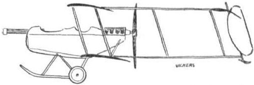
Designed by A. R. Low and G. H. Challenger, the Gunbus series of two-seat pusher biplanes originated from an Admiralty contract received on 19th November, 1912, for an experimental biplane to carry a machine-gun for offensive operations. In the absence of a suitable interrupter gear, the pusher lay-out was selected to provide as wide a field of fire as possible for the belt-fed Vickers-Maxim gun.
The prototype E.F.B.1 (Experimental Fighting Biplane No. 1) No. 18 Destroyer was ready in time to be displayed on the company's stand at the 1913 Olympia Aero Show. The gun was mounted in the nose of the duralumin-covered nacelle and moved in a slot which allowed 60° vertical and horizontal sweeps. The two-bay, unequal-span wings carried the nacelle on the lower planes, the monoplane tail unit with its rectangular tailplane being borne on tubular steel booms to the rear. The wings were staggered and were warped for lateral control. The upright struts in the booms were raked forward, and this applied to the rudder also. The engine installed was the eight-cylinder 80 h.p. Wolseley air-cooled vee with water-cooling for the valves.
The E.F.B.1 is believed to have crashed on its first test flight, but, as the design was considered promising, development proceeded into the E.F.B.2.
<...>
SPECIFICATION (E.F.B.1)
Description: Two-seat pusher fighter biplane. Wood and steel structure, fabric covered.
Manufacturers: Vickers Ltd., Imperial Court, Knightsbridge, London, S.W.I.
Power Plant: 80 h.p. Wolseley.
Dimensions: Span, 40 ft. Length, 27 ft. 6 ins. Wing area, 385 sq. ft.
Weights: Empty, 1,760 lb. Loaded, 2,660 lb.
Performance: Maximum speed, 70 m.p.h. Landing speed, 40 m.p.h. Climb, 450 ft./min. Endurance, 4.5 hrs.
Price: ?1,800.
H.King Armament of British Aircraft (Putnam)
Vickers
Gun Bus. Late in 1912 the Vickers drawing office was laying out a large twin-engined biplane known as No.14B, to be armed with a 1 1/2-pounder semiautomatic gun, possibly of the type later fitted to the Sopwith No.127 and Short No.126 pusher seaplanes. The Vickers machine never materialised, but an outgrowth of the technical studies made was the pusher gun-carrying aeroplane which appeared at the Olympia Aero Show in London during February 1913. This was named Destroyer, and mounted in the nose of the duralumin-covered steel-tube nacelle was a Vickers belt-fed 0.303-in machine-gun on a mounting which allowed the gun to swivel through 60 degrees in both elevation and azimuth. The ammunition box was stated to be stowed 'just over the centre of pressure of the planes', the intention being that it should be wound forward on wire rails to its action station. That this aeroplane is stated to have crashed on its first flight because of nose-heaviness occasioned by its armament is not altogether surprising.
The Destroyer, or E.F.B.1, had been built to Admiralty order, and early in 1913 a gun mounting for a machine of the type (there can be no doubt of this, by reason of the raked nacelle-struts shown in an accompanying drawing) was designed by Lieut C. J. L'Estrange Malone of the Admiralty's Air Department. With this Department other notable developments in aircraft armament, notably the Scarff ring-mounting, were later to be associated.
The Admiralty mounting appears to have been designed after the appearance of the Destroyer at Olympia and may indicate the sponsor's dissatisfaction with the original Vickers installation, for the aircraft had been built to an Admiralty order placed in November 1912. Certainly the mounting suggests a closer association between the Admiralty and the Gun Bus than has hitherto been recognised.
The Admiralty mounting consisted of a cradle or frame which could rock in a vertical plane and also rotate in azimuth. At one end of this member, the gun was carried on a universal joint; at the other end was the gunner's seat. The cradle was curved in form and was mounted on a horizontal pivot carried in a bracket which itself had a vertical swivelling pin stepped in a socket attached to the aircraft structure. A handwheel operating a worm gear was provided for traversing.
P.Lewis The British Fighter since 1912 (Putnam)
A more conventional approach to the same type of aircraft was visible in the Vickers E.F.B.1 which was displayed on the Company’s stand at the same 1913 Olympia Aero Show. The Vickers machine had been designed by A. R. Low and G. H. Challenger to meet the requirements of an Admiralty contract, which the firm had received on 19th November of the previous year, calling for an experimental biplane armed with a machine-gun for offensive use. Equipped also with the bellicose name Destroyer, the first example of the Gunbus series followed, too, the pusher style forcibly dictated by circumstances at the time for any gun-carrier. Constructed under Vickers number 18, the E.F.B.1 was given two-bay, staggered wing cellules of unequal span. Composite construction was employed, with wood being used mainly but with tubular steel forming the tail booms and duralumin the covering of the two- seat nacelle. No. 18’s engine was an eight-cylinder V, air-cooled Wolseley developing 80 h.p. with water-cooled valves. The Destroyer’s all-important armament consisted of a Vickers-Maxim machine-gun installed in the nose coaming and capable of being aimed through a slot with 60° vertical and horizontal movement. This form of mount was not particularly satisfactory with its restriction on speed and in freedom of movement of the gun. Belt-feeding of the cartridges proved particularly awkward, both in following the gun as it was swung and in storing satisfactorily in the limited space in the nose. The E.F.B.1 is thought to have crashed the first time that it left the ground but was believed to hold such prospects of ultimate success that a revised version was put in hand. The E.F.B.1’s important distinction is that it represented the first serious attempt at designing from the start a true fighting aeroplane for the British services without being compromised by being simply a modification of an existing airframe.
F.Mason The British Fighter since 1912 (Putnam)
Vickers E.F.B.1 Destroyer
One of the earliest fighting aeroplane requirements, if not the first, issued by the Admiralty after the creation of the Naval Wing of the RFC in 1912, was for a gun-carrying machine whose armament was intended to be used for offensive as distinct from purely defensive purposes. Thus, by implication owing to the inability to fire forward through a tractor propeller, this dictated the pusher biplane configuration.
Vickers, Sons & Maxim Ltd had produced aeroplanes since January 1911, almost all monoplanes, but late the following year Major Archibald Reith Low and George H Challenger set about the design of the first of the famous Gunbus series, the E.F.B.1 (Experimental Fighting Biplane); it was also named the Destroyer, and earned a contract for Vickers early in 1913.
Employing two pairs of steel tail booms attached at their forward ends to the rear spar of the mainplanes and converging to meet at the sternpost, the two-seat aircraft featured generous wing stagger, and the forward raking of the interplane struts was matched by the rake of the tail boom struts, thereby lending the aircraft an air of aggression. The internal structure was of steel tube throughout, the wings being fabric-covered and the nacelle clad in duralumin sheet.
A 60/80hp Wolseley eight-cylinder vee air-cooled engine drove a Vickers-Levasseur two-blade propeller with scimitar-shaped blades. The front cockpit was occupied by the observer who was provided with a 0.303in Vickers-Maxim gun, mounted so as to traverse through 60-degree lateral and vertical arcs.
The E.F.B.1 was displayed at the 1913 Olympia Aero Show, but unfortunately crashed soon afterwards - possibly on its first flight - almost certainly owing to longitudinal instability.
Type: Single pusher engine, two-seat fighting biplane.
Manufacturer: Vickers Ltd, Erith, Kent.
Powerplant: One 60/80hp Wolseley eight-cylinder air-cooled engine driving a four-blade Vickers-Levasseur pusher propeller.
Structure: Fabric-covered, all-metal twin-spar wings with two pairs of steel tubular tail booms. Duralumin sheet-clad, steel-frame nacelle. Skid-and-wheel undercarriage.
Dimensions: Span, 40ft 0in; length, 27ft 6in; height, 11ft 11in; wing area, 380 sq ft.
Weights: Tare, 1,760lb; all-up, 2,660lb.
Performance: Max speed, 70 mph at sea level; initial climb, 450 ft/min; endurance, 4 1/2 hr.
Armament: One 0.303in Vickers-Maxim machine gun in nose of nacelle.
Prototype: One. No production.
W.Green, G.Swanborough The Complete Book of Fighters
VICKERS E.F.B.1 UK
On 19 November 1912, Vickers received a contract from the Admiralty for an experimental fighting biplane armed with a machine gun. Various configurations were investigated before the desirability of placing the gunner in the extreme nose of the aircraft, in order to achieve a clear field of fire, led to choice of a fuselage nacelle carrying at its rear an engine driving a pusher propeller. This nacelle was mated with an unequal-span heavily-staggered biplane configuration, the tail surfaces being carried by paired and vertically dis¬posed booms attaching to the upper and lower rear wing spars on each side of the engine. Designated E.F.B. (Experimental Fighting Biplane) 1 and dubbed “Destroyer", the Vickers aircraft was, if not the very first, then one of the earliest dedicated fighter aircraft, and was armed with a single 0.303-in (7,7-mm) Maxim machine gun on a mount affording 60 deg elevation and traverse. The airframe of the E.F.B.1 was primarily of metal construction, the nacelle accommodating the pilot and gunner, and carrying an 80 hp Wolseley eight-cylinder Vee-type engine, being of steel tube with duralumin skinning. Wing warping was employed for lateral control. Prior to its first flight, the E.F.B.1 was displayed at the Aero Show held at Olympia, London, in February 1913. The gun was fitted for the first flight test, made at Joyce Green, but this rendered the aircraft so nose-heavy that it briefly left the ground, then nosed down, struck the ground and turned over. The following performance data are estimated.
Max speed, 70 mph (113 km/h) at sea level.
Initial climb, 450 ft/min (2,3 m/sec).
Endurance, 4.5 hrs.
Empty weight, 1,760 lb (798 kg).
Loaded weight, 2,660 lb (1207 kg).
Span, 40 ft 0 in (12,19 m).
Length, 27 ft 6 in (8,38 m).
Height, 11ft 11 in (3,63 m).
Wing area, 385 sq ft (35,77 m2)
Jane's All The World Aircraft 1913
VICKERS. Vickers, Ltd., Vickers House, Broadway, Westminster. School: Brooklands. Seven pupils qualified during 1912.
Monoplane. Military
Model and date. 1912-13. biplane.
2-seater. 1913.
Length................feet(m.) 25 (7.60) ...
Span..................feet(m.) 34? (10.50) 40 (12.20)
Area..............sq.feet(m?.) 220 (20) 385 (35)
Weight,total........lbs.(kgs.) 730 (331) ...
Weight, useful......lbs.(kgs.) ... ...
Motor.....................h.p. 80 Gnome 80 Wolseley
Speed..............m.p.h.(km.) 70 (115) ...
Endurance.................hrs. 3 ...
Number built during 1912...... ... ...
Notes.-- Steel construction. Landing shock absorbing: 2 wheels and 1 skid. Rectangular enclosed body. Controls: warping and rear elevator.
Monoplane climbs 300 feet a minute fully loaded.
Biplane is armed with a Vickers R.C. automatic gun in the bow.
Журнал Flight
Flight, February 8, 1913.
WHAT THERE WILL BE TO SEE AT OLYMPIA.
THE MACHINES.
Vickers, Ltd.
Two machines, of excellent design and construction, will represent Messrs. Vickers, Ltd., at the Olympia Show. One will be a military biplane, driven by one of the new Wolseley 60-80 semi-air-cooled semi-water-cooled motors. Their other machine will be a monoplane similar in almost every respect to the one which flew in connection with the Military Trials at Salisbury Plain. Unlike that machine, however, it will be driven by a 70-h.p. Gnome motor. From the side elevation sketch we print can be gathered an idea of the arrangement of the new Vickers biplane. It may be considered as an all-steel machine, for wood only enters into its construction for the manufacture of ribs and skids, and for the "stream-lining" of steel tubular struts. The planes, which are staggered, are each built about two wood-filled tubular steel spars, over which the ribs are loosely threaded in such a way that it is impossible for the plane skeleton to become fatigued through continual warping. For this reason also the rear spars in the sections of the planes which warp are hinged to the spars of the rigid central section. The upper and lower planes span 40 and 30 ft. respectively. They are separated by steel stanchions, which are assembled to the planes by means of a special design of socket, by which the planes can be dismantled in a very short space of time. The body of the machine is of steel construction, covered by a "stream-lining" of Duralumin. Projecting in front of the machine, as it does, it affords the observer, who occupies the front seat, an uninterrupted view. More important than that, this design makes it possible for the biplane to be used as a machine for offence purposes. On the machine that will appear at the show, it will be seen that Messrs. Vickers have mounted a Maxim gun, which can be swiveled through an angle of 30 degrees on either side of, and below and above, the longitudinal axis of the machine. In a box, arranged inside the cockpit at the centre of gravity of the machine, will be stored 1,500 rounds of ammunition. This box is so fitted that it may slide forward on wires and so be brought within easy reach of the man who is operating the gun. The pilot sits in the rear seat, but both pilot and passenger are provided with controls by which they may drive the machine. The landing gear is similar in design to that fitted to the B E a Army biplane. Like that latter machine, too, the Vickers biplane may easily be steered at slow speeds over the ground. A Vickers-Levasseur propeller will be used.
<...>
Flight, February 22, 1913.
SOME MORE AEROPLANES AT OLYMPIA.
MESSRS. VICKERS, LTD.
They are represented by two exceedingly businesslike looking machines, an 80-h.p. Gnome engined monoplane and a military biplane equipped with one of the new 60-80-h.p. Wolseley aero motors. For some three years now has this noted firm had in operation an aviation department under the direction of Capt. H. F. Wood, himself a pilot of no mean order. Their designer, Mr. Archibald R. Low, M.A., who is responsible for the drawings of the two machines exhibited, is also an experienced pilot. Both the monoplane and the biplane shown may to all intents and purposes be considered as all-steel machines, for wood only enters into their construction for the shaping of the ribs, for the landing skids, and for the filling pieces by which the tubular struts are brought up to streamline section.
<...>
The 60-80-h.p. Vickers Biplane. - A very interesting machine, not only for the fact that, hitherto, the Vickers organisation have confined their attentions exclusively to monoplane construction, but for the great amount of thought and care that, it is evident, has been spent on its construction and design. Standing before this biplane, the first feature that arrests the attention is that there is a Vickers automatic gun protruding from the front of the neatly rounded Duralumin covered body. Then, even the lay mind can arrive at the principal reason why the propeller has been arranged at the rear of the machine - it is designed to have that position mainly in order to give an unobstructed range of fire in front of the biplane.
The body of the machine, which extends forwards from the main planes, is constructed in a precisely similar manner to that of the monoplane we have just described. In its interior sit the passenger and behind him the pilot, both sheltered to a great extent from the wind by the neat metallic covering that is fitted over the body. Seated in front, the observer, and he will have to be a gunner too, has a perfectly clear view all around him. The gun before him is arranged to swivel through an angle of 60° in both horizontal and vertical planes, while the ammunition is stored in a box, travelling on wires, beneath his seat. When the gun is not in use the ammunition box is in a position just over the centre of pressure of the planes; when it is required to operate it, the box is wound forward on its wire rails and brought within reach of the gunner. As we have remarked, the pilot sits immediately behind him, and he grips a double-handled vertical lever whereby he controls the machine. Still further behind, the motor is mounted, its lugs bolted to the top two members of the fuselage.
The planes are made on a system which has little difference from that observed in the building of the Vickers monoplane wings. They are "staggered," as will be seen from one of our illustrations. Contrary to the more usual plan of using piano wire for the bracing of the planes, stranded steel cable is employed in this machine. As a matter of fact, all the bracing throughout is of stranded cable, excepting in the body, where stout wire is used. The planes are so designed that in a very little time they may be dismantled, leaving only a centre section that is no wider than the body itself. Close examination of this central section of the top plane will reveal that in its interior there is a small petrol tank from which fuel is fed to the motor by gravity. It is supplied from a main tank in the body, under pressure, and the tubes leading to and from it are neatly tucked away behind the wooden tilling pieces that are used to "streamline" the tubular cellule spars. By the way, the machine does not carry an oil tank, for sufficient oil is stored in the base chamber of the motor to last for a six hours' flight.
The landing chassis is, at first sight, very much like that of the monoplane. Its flexible suspension, however, will be found to be altogether different. A central hollow skid of ash is joined to the body by 2 V's of steel tubing. Two other V's of tubing extend downwards and outwards from the side of the body, and, in crutches at their lower extremities, the axles of the landing wheels travel against the tension the strong rubber springs. (See sketch.) Altogether, the chassis is exceptionally light and compact, and, moreover, looks strong enough to bear any ordinary landing strain that it is likely to he subject to. Differing from the monoplane, too, there is no backward extension of the central landing skid. The weight of the tail is carried by a small steel spoon-shaped tail skid, so fixed that it pivots with the rudder and enables the machine to be steered more or less accurately over the ground at slow speeds.
The tail, level with the top main plane in flight, is attached to the top of the tubular steel tail outriggers. In plan form it is approximately rectangular, and its interior construction is of steel throughout, tubing being used for its outline, while the cambered ribs are of channel section, acetylene-welded in position.