M.Goodall, A.Tagg British Aircraft before the Great War (Schiffer)
Deleted by request of (c)Schiffer Publishing
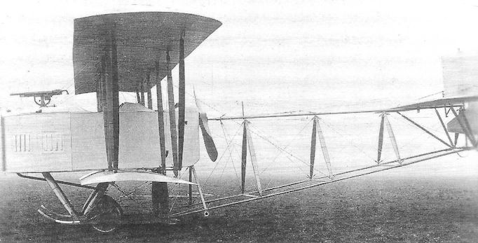
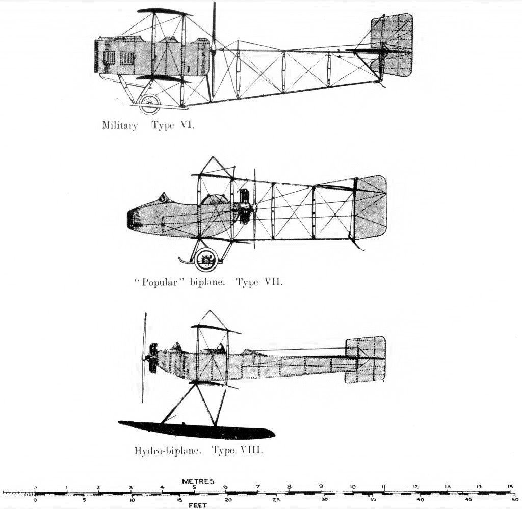
GRAHAME-WHITE Military biplane Type VI
This two-seater pusher biplane was shown at Olympia in February 1913 and was one of the earliest attempts to produce an aircraft with offensive capability.
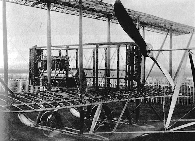
The engine was front mounted driving the propeller, through shaft and chain, at the rear of the nacelle. A Colt machine-gun above the engine, with a wide field of fire, could be operated by a gunner in the front cockpit.
An unusual feature was the triangular section rear boom consisting of tubular longitudinal members, the top one protruding forward through a bearing in the propeller boss, enabling the control wires to pass through to the tail.
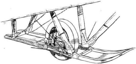
The undercarriage incorporated wide skids, which carried the wheels on sprung mountings. The wheels each had two rims fitted with separate tires to prevent canting of the wheels on bumpy surfaces. Roll control was by wing warping.
The basic design was attributed to Horatio Barber, with J.D. North responsible for the final design work.
Power: 90hp Austro-Daimler or 120hp Austro-Daimler six-cylinder inline water cooled driving a 10ft diameter Chauviere propeller through shaft and Brampton chain.
Note: The engine fitted at the Olympia Show was of 90hp. It is doubtful if the 120hp Austro-Daimler was ever fitted for little was heard of this machine after the Show.
Data
Span top 42ft 6in
Span bottom 23ft
Chord 6ft lin
Gap 7ft
Length 33ft 9in
Wing area 435 sq ft
Area tailplane 50 sq ft
Area elevators 25 sq ft
Area rudder 20 sq ft
Weight empty 2100 lb
2200 lb with 120hp engine
Weight allup 2750 lb
2850 lb with 120hp engine
Speed 50-70 mph
Endurance 6 hours
P.Lewis British Aircraft 1809-1914 (Putnam)
Grahame-White Type 6
J. D. North designed the Type 6 Military Biplane which was exhibited at the 1913 Olympia Aero Show. The tail was supported on three booms, the uppermost of which was used as a bearer for the propeller, with the control wires for the tail passing through the centre of the propeller boss. This arrangement originated with Horatio Barber. The 120 h.p. Austro-Daimler scheduled for the machine was not fitted at the Show, its place being taken by the 90 h.p. Austro-Daimler. This was mounted at the front of the deep nacelle, an extension shaft passing to the rear to drive the propeller by a chain. The Colt machine-gun in the nose had a 50° vertical and 180° horizontal field of fire. In addition to the pilot, two passengers were carried at the front of the nacelle and were accommodated on sprung seats over the tool boxes on each side of the engine. The controls were mounted on ball-bearings. Span, 42 ft. 6 ins. Length, 33 ft. 9 ins. Wing area, 440 sq. ft. Weight empty, 2,200 lb. Weight loaded, 2,950 lb. Maximum speed, 70 m.p.h. Landing speed, 50 m.p.h. Endurance, 6 hrs.
H.King Armament of British Aircraft (Putnam)
Grahame-White
1913 War Plane (Type 6). A Browning machine-gun on a British fighting aeroplane of 1913: this was but one blood-quickening feature of this pusher biplane, exhibited at Olympia early in the year mentioned. A second feature was the arrangement of the power plant to allow the free mounting of a gun. Thus The Aero:
"The engine is coupled up to a long shaft mounted on ball bearings which extends back t o behind the pilot's seat, where it carries a chain sprocket driving the propeller through a twin roller chain. The propeller is mounted so that the upper longitudinal member of the triangular-section fuselage is taken through its hub, the principal reason for this being that with this design the arrangement of the fuselage is simplified, and the engine can be carried in front without introducing the necessity for the pilot and passengers to sit immediately in the slip stream of the screw."
Almost as an afterthought there was appended to a lengthier description the simple observation:
'The machine is shown equipped with a quick-firing gun'.
Let it now be placed on record, after well over half a century, that this layout was schemed bv Horatio Barber; that the detail design was the work of John D. North, who was to adapt a Box Kite for a Lewis gun demonstration at Bisley in November of the same year (the War Plane never flew) and who in later years became a pre-eminent figure in aircraft armament development; and that the gun at Olympia, though correctly described by the commercial name Colt, was of the type called Browning Model of 1895 (or 'potato digger'). Like the later Lewis, this gun was air-cooled. The gun-pillar was associated with a quadrant fixed in a vertical plane under the gun. Elevation was said to be possible over an arc of 50 deg and traverse over 180 deg. The allusion to 'passengers', it may be noted, signified that an observer was carried in this aeroplane as well as a gunner.
P.Lewis The British Fighter since 1912 (Putnam)
J. D. North, designer to Claude Grahame-White’s concern at Hendon, tried his hand at a gun-carrier with the Type 6 Military Biplane which was ready in time for display at the 1913 Aero Show at Olympia. Designed on comparatively unorthodox lines, the machine was fitted with an Austro-Daimler engine mounted in the nose of the deep nacelle. The crankshaft was extended rearwards the length of the nacelle, where it was connected to the two-blade propeller by a chain drive. The propeller itself revolved around the upper tubular tail-boom which acted also as its bearing. This feature was reminiscent of the arrangement adopted in the Royal Aircraft Factory’s F.E.3 but the Type 6’s tail had the benefit of additional support from a pair of lower booms making in all a rigidly-braced triangular framework. The bore of the uppermost boom was used to carry the control wires to the rudder and elevators. Centre-section struts were omitted, the upper wings being carried across the nacelle by the inner interplane struts. Twin pairs of main wheels were suspended in slots in ski-shaped skids, and the nacelle carried two passengers on the sprung tops of the tool boxes on each side of the engine, the pilot being accommodated behind them. The Type 6’s single machine-gun was a Colt installed in the nose with 50 vertical and 180 horizontal field of fire.
F.Mason The British Fighter since 1912 (Putnam)
Grahame-White Type 6
An almost exact contemporary of the Royal Aircraft Factory’s F.E.3, the Grahame-White Type 6 gun-carrier was designed by John Dudley North, the 19-year-old graduate of the Aeronautical Syndicate who joined Claude Grahame-White at Hendon in 1912. Like the F.E.3, North’s Type 6 also used a tail boom which passed through the pusher propeller shaft.
However the design differed in several important respects. Careful to avoid a lack of torsional rigidity in the tail unit (which was to lead to the F.E.3 being grounded), North retained two conventional steel tubular tail booms below the propeller shaft boom, thereby obtaining a triangular section structure that could be cross-braced to provide greater strength. Like the F.E.2, the engine, this time a 90hp Austro-Daimler, was located in the front of the nacelle - completely enclosed - but in this instance the engine’s crankshaft itself was extended aft, below the cockpits, to chain reduction sprockets at the rear of the nacelle. The observer-gunner’s cockpit was located in the centre of the nacelle, with the pilot’s cockpit immediately behind him.
A 30-calibre Colt machine gun on a flexible mounting, capable of traversing 90 degrees either side and 50 degrees in azimuth, was positioned in front of the gunner’s position.
Grahame-White was clearly competing against Farnborough’s F.E.2 and F.E.3, as well as Vickers’ Gunbus, for Admiralty orders, and his Type 6 duly appeared at the 1913 Olympia Aero Show. When, however, the Farnborough pilots criticised the suspect tail support structure of the F.E.3, interest centred on the Vickers E.F.B. series. North accordingly abandoned the unorthodox tail boom arrangement and in his next gun-carrier essay, the Type 11, adopted the conventional four-boom layout.
Type: Single pusher engine, two-seat, fighting biplane.
Manufacturer: The Grahame-White Aviation Co Ltd, Hendon, Middlesex.
Powerplant: One 90hp Austro-Daimler water-cooled in-line engine driving two-blade pusher propeller.
Structure: Predominantly steel tubular structure with fabric-covered parallel-chord unstaggered wings; three-boom tail support structure. Skid-and-wheel undercarriage.
Dimensions: Span, 42ft 6in; length, 33ft 9in.
Weights: Tare, 2,2001b; all-up, 2,950lb.
Performance: Max speed, 70 mph at sea level; initial climb, 340 ft/min; endurance, 2 3/4 hr.
Armament: One 30-calibre Colt machine gun on nose of nacelle.
Prototype: One. No production and no Service number allotted.
Jane's All The World Aircraft 1913
GRAHAME-WHITE. The Grahame-White Aviation Co., Ltd., 166 Piccadilly, London, W. Works and Flying Ground: Hendon. Founded by C. Grahame-White, the well-known aviator, who in 1909 commenced operations with a school at Pau. Later this was removed to England, and a general agency for the sale of aeroplanes, etc., established. This developed, and early in 1911 the firm was handling a special British agency for the U.S. Burgess type known as "The Baby." The Hendon Aerodrome was acquired, and a factory established, which has grown continually ever since. In April, 1912, a monoplane to special design was completed. By the close of the same year biplanes of advanced design were constructed. Capacity of the works, March, 1913, was equal to 150 machines a year if necessary.
| 1913. |1913. |1913. |1913 |1913.
|Military |"Popular" |"Popular" |Tractor |Monoplane.
|biplane. | biplane |biplane |hydro- |Type IX.
|Type VI. |Type VII. |Type VII. |biplane | single-
|2-seater |2-seater. |2-seater. |2-seater.| seat.
-----------------|-----------|-------------|-------------|---------|----------
Length...feet(m.)|33? (10.10)|20-5/6 (6.40)|26-5/6 (8.22)|25 (7.60)|21 (6.40)Span.....feet(m.}|42 (12.80)|29-1/6 (8.85)|38 (11.60)|42? (13) |32 (9.75)
Area..sq.ft.(m?.)|435 (40?) |230 (21) |475 (44) |380 (35) |208 (19)
Weight, total ...| | | | |
.......lbs.(kgs.)|2200 (997) | ... | ... |850 (385)| ... Weight, useful...| | | | |
.......lbs.(kgs.)| 750 (340) | ... | ... |450 (204)| ...
Motor | 120 Aust. | 50 Gnome | 50 Gnome |80 Gnome |50 Gnome
| Daimler | | | |
Speed, max... | | | | |
...m.p.h (k.p.h.)|70 (110) |60 (95) |50 (80) |65 (105) |65 (105)
Speed, min... | | | | |
...m.p.h (k.p.h.)|55 (90) |50 (80) |40 (65) |50 (80) | ... Endurance....hrs.| 6 | 4 | 4 | 4 | 4
Number built | | | | |
during 1912 | 1 | ... | ... | 1 | ...
-----------------|-----------|-------------|-----------------------|-----------
|Also built | Also built | |Also built|Also built
|with a 90 | with a 35 | |with a 60 |with a 35
|Aust.Daimler.| Anzani. | |Anzani. |Anzani. Two
|Designed to| | | |main floats
|carry a gun| | | |with 12?
|on the bow.| | | |ft. track.
|Very good | | | |Floats are
|view. Very | | | |15 ft.long,
|strong | | | |2 ft. wide,
|landing | | | |1 ft. 3 in.
|carriage. | | | |deep.
Журнал Flight
Flight, February 8, 1913.
WHAT THERE WILL BE TO SEE AT OLYMPIA.
THE MACHINES.
The Grahame-White Aviation Co., Ltd.
This progressive firm, the proprietors of the popular London Aerodrome at Hendon, will be showing two biplanes, one a land machine and the other designed for water flying. The first of these machines is equipped with a 90-h.p. Austro-Daimler motor which drives through a steel shaft and chains, a large diameter propeller arranged to the rear of the main planes so that the machine may be used for offensive tactics in war. The motor is mounted at the front of a streamline nacelle. The pilot, sitting behind it, is in a position that makes for maximum safety, should the machine for any reason suffer an unusually heavy landing. The main planes are of the extensioned type, the top plane being considerably longer in span than the lower. For the landing gear, it is exceptionally strong, and has the original feature that each of its two running wheels is flexibly mounted in a slot cut in each of the two unusually wide built-up skids. The tail is supported by an open triangular construction, the top member of which passes through the propeller boss. The second machine that the Grahame-White Co. will be showing will be a two-seater tractor hydro-biplane, driven by a 60-h.p. Anzani air-cooled motor. Its body will be somewhat reminiscent of Nieuport design, and it will be fitted with a pair of main floats of the long catamaran type. In addition, there will be exhibited on the stand various specimens of workmanship, such as a set of propellers, showing them in different stages of manufacture.
Flight, February 15, 1913.
GRAHAME WHITE AVIATION CO., LTD.
Two notable biplanes figure on their stand, one a 90-h.p. military machine, and the other a hydro-biplane of a sporting type, driven by a 60-h. p. Anzani motor. Both bear evidence of much thought on the part of the designers, and of much painstaking care spent upon them in the constructing shops. The design of the first of these machines was due originally to Mr. H. Barber, but in its working out he was assisted by Mr. J. D. North, who also prepared the drawings for the hydro-biplane. Let us confine our attention for the moment to the military machine.
The Grahame-White Military Biplane, as its title conveys, is a machine specially devised for military purposes, and particularly so that its occupants may be able to undertake offence tactics. So that the occupants may have a clear outlook in front of their respective cockpits, the propeller is arranged to the rear, while by using shaft drive the front engine position is retained, a disposition of the motor that is generally thought to be the best from the point of view of the passengers' safety. This machine was originally designed for a motor of 120 h.p., but it appears at the Show temporarily fitted with one of only 90 h.p. To illustrate its application as an aeroplane for attack purposes, a Colt quick-firing gun is mounted in the nose of the machine, and it has a range of 50° in a vertical plane, and 180° horizontally. It would, of course, be impossible for the gunner to make use of the gun's full extent of horizontal range - he would probably only be able to sight it through a deviation of 45° on either side of the longitudinal axis of the machine.
The body of the biplane is essentially a lattice girder with ash longerons, and ash and spruce cross-members, ash being used for the latter members in the neighbourhood of the engine and propeller. That perfect rigidity may be assured, and this is doubly essential in the case of the body of this particular machine on account of its having a transmission shaft mounted inside it, it is double cross-braced with 10-gauge piano wire. In plan, the body is shaped to a careful streamline form, and it is an interesting point that the strut cross-sections are of the same shape, excepting that their curves are plotted to a shorter longitudinal axis. The Austro-Daimler motor is mounted on high ash bearers in front, and drives the propeller, a 10 ft. Chauviere, through shaft and chain transmission. The shaft is a large diameter steel tube turning in self-aligning ball-bearings, and the chain employed is a duplex Brampton. Fitted at the extreme nose of the body is a honeycomb radiator, specially made by the Austro-Daimler firm, and so shaped that it preserves the lines of the body. There is room on either side of the engine for a passenger to sit. They are provided with unusually comfortable spring seats, while under their feet are tool boxes. The pilot sits behind them and controls the machine by a vertical lever governing the elevation and wing warping, and by a pivoted foot lever which operates the rudder. To ensure sweet working, all the controls are carefully mounted on ball-bearings, and all the pulleys used to guide the control wires are turned from vanalium and fitted with ball-bearing centres. Below the pilot's feet is a large petrol tank sufficient for a 6-hours' flight. From that tank, petrol is fed under pressure, automatically provided by the engine exhaust, to a service tank in front, above the level of the engine. The pilot can at all times acquaint himself as to the state of his petrol supply by a specially devised gauge on his left.
Plane construction. - The planes span respectively 42 ft. and 23 ft. and, having a chord measurement of 6 ft., they have a supporting area of 390 sq. ft. The cross-section employed is that of the Eiffel plane No. 8. The interior construction of the plane is particularly interesting. The front span is of generous dimensions, shaped from spruce. The rear span is a wide diameter steel tube. Over the spars are loosely fitted the ribs in such a manner that continual warping of the planes does not fatigue the structure. The ribs are built up of spruce webs and flanges, and where the spars are threaded through them they are thickened up to the full width of the flanges. To strengthen the planes against drift, they are cross-braced inside with 5/32 in. stranded cable, and so that the tension of the braces shall not cause the spars to pull together and so bind the ribs, they are separated by adjustable steel rods.
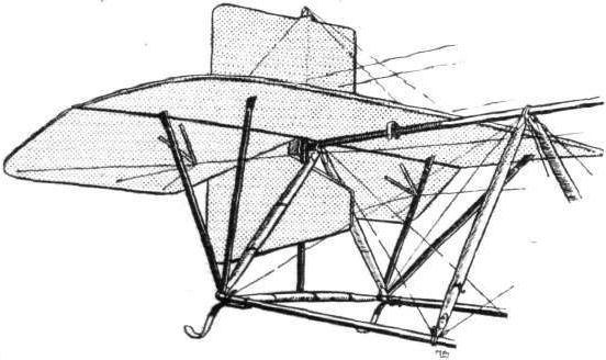
The landing gear is composed of two built-up skids, each a little over a foot wide, in the centres of which are mounted the landing wheels. These latter organs each have two rims to the one wheel and are so designed to prevent the wheel from canting over sideways, which is, with a single tyre wheel, a very likely thing to happen with the method of suspension used. One of our sketches illustrates this point. The body of the machine is supported from the skids by 10 hollow spruce struts, the front two of which are taken straight to the engine bearers.
The tail, consisting of a flat stabilizing surface 50 sq. ft. in area, two elevator flaps of a combined area of 25 sq. ft., and a vertical rudder of 20 sq. ft. surface, is stayed at the end of an open girder construction, built up of three steel tubular longerons and hollow spruce struts. The top member of this girder, as will be seen from our sketches, passes through the propeller boss.
The Grahame-White military biplane weighs, without passengers or fuel, 2,103 lbs., and is designed to carry a useful load of 750 lbs. With her 120-h.p. engines fitted, she is expected to have a speed range of from 50 to 70 miles per hour.
<...>