S.Ransom, R.Fairclough English Electric Aircraft and their Predecessors (Putnam)
Coventry Ordnance Works Military Trials Biplanes
During the summer of 1911, Col J.E.B. Seely, Under Secretary for War, announced that the War Office was considering offering prizes for an aeroplane suitable for military use. By October, plans for a competition were being formed, and early in December, an Aeronautical Society meeting, held at the Royal United Services Institute, London, provided an opportunity for open discussion between the Army and aircraft constructors regarding the requirements of military aircraft. Among those present at the meeting were W.O. Manning and Howard T. Wright, representing the Coventry Ordnance Works Ltd, which had just taken over Wright's business under the railway arches at Battersea. The meeting proved so successful that a second one was arranged but before this took place the War Office announced the conditions and prizes for its competition to be held at Larkhill in August 1912. The directors of the Coventry Ordnance Works, on hearing the details of the competition, decided to enter aircraft for what became known as the Military Trials and accordingly authorised Manning and Wright to proceed with the design and manufacture of suitable machines.
Manning set to work immediately after the decision had been made and soon produced two designs, both of unequal-span tractor biplanes, one having its two crew seated side-by-side and the other with its two crew seated in tandem. Powerplants chosen were the 100 hp Gnome, fourteen-cylinder rotary and the 110 hp Chenu inline water-cooled engine. Their installation was decided from consideration of frontal area and the Chenu engine was therefore fitted to the tandem-seat design, which had a narrow fuselage with a short rounded top-decking immediately behind the open cockpit. The fuselage of the Gnome-powered biplane was untapered in plan and necessarily broad but tapered rearwards in side elevation two faired head-rests being provided for the crew. Both machines had their fuselages mounted above the lower wing, which was attached at its centre-section by four pairs of short struts, the centre pairs forming a framework for a streamline fairing that enclosed the petrol tank. The upper wing of each biplane was carried solely by four pairs of interplane-struts and was made in five sections. The outboard sections of the upper wing were braced from kingposts and could be warped for lateral control. The wings of the Gnome-powered biplane were tapered in plan and those of the other machine were of parallel chord. There was no centre-section cut-out in either wing of the Gnome-powered aircraft when it first appeared at Brooklands but they were incorporated within a month of its debut. The fixed tail surfaces of the Gnome-engined aircraft were semi-elliptical in planform, and those of the other of triangular shape. The elevators, fin and rudder of the two machines were distinctive in arrangement. The Gnome-powered biplane had three-quarter circular elevators, with the forward quarter forming a horn-balance, small twin triangular fins, each mounted in line with the fuselage sides, and twin elliptically-shaped rudders, which each had two horn-balances. The Chenu version had a single triangular fin and horn-balanced rudder and elevators of shark's fin shape. Each machine's undercarriage was unsprung and relied upon its low-pressure balloon tyres to absorb landing shocks.
Construction of the Gnome-powered Military Trials Biplane started at Battersea early in 1912 with the manufacture and assembly of its fuselage, the metal fittings for which were made at COW's factory at Coventry. The fuselage was a wire-braced box-girder structure with four ash longerons and spruce spacing-struts. The forward ends of the longerons were bent using steam and fitted into two steel pressings, which carried the engine and propeller shaft, the latter being mounted above and driven by a 1 1/2 in Renold roller chain through a 2: 1 reduction gear from the engine. The Gnome engine was fitted with Bosch dual ignition and could be started from the cockpit. Nine laminations of teak were used for the Manning-designed two-blade propeller, the inner region of which gave low thrust to reduce drag and pilot discomfort from the slipstream. The propeller hub had the additional refinement of a spinner. Engine and nose fuselage cowling was cut from sheet aluminium and attached by means of car-hood fasteners. A 10 Imp gal gravity petrol tank and a 22 Imp gal oil tank were carried in the bay behind the engine, the gravity tank being supplied with fuel pumped from the 40 Imp gal tank carried in the fairing between the fuselage and lower-wing centre-section.
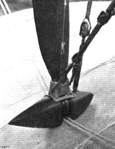
Pilot's controls comprised a wheel at the top of a pivoted control column and a rudder bar. Dual rudder control was later installed. Both wings were built-up on two I-section ash spars and a thinner intermediate spar, and had solid ribs of Eiffel No. 8 aerofoil section, lightened with holes between the spars. The fabric-covered wings were internally braced by wires, inspection of their joints and those of the spars being made through sliding aluminium panels. Interplane-struts and kingposts were of streamline section and made from silver spruce. Stranded cable was used for external bracing and warping wires, the latter passing through pulleys housed in streamline fairings. All tail surfaces had flat wooden frameworks and were fabric covered. Undercarriage and nose skid struts were made of Honduras mahogany, the skid itself being of hickory. A small tusk was fitted inboard of each spoked wheel to prevent the apex of each undercarriage leg from digging into the ground in the event of the spokes breaking. The tailskid was of bent cane and was fitted with a simple but effective braking device, comprising a spring-steel claw which was always operative unless drawn clear of the ground by the pilot pulling the wire attached to it and fastening this to a hook near his seat.
About the end of April 1912, the components of the Gnome-powered biplane were taken to Brooklands and there assembled in hangar No.32, which had also been taken over by COW from Howard Wright. Its debut at Brooklands created considerable interest and an aviation journalist writing for Aeronautics was later to record: 'In strength, in neatness and finish of design, in minute attention to detail, nothing finer than this splendid biplane has ever been produced m the country.' The biplane's first flight was made shortly afterwards by T.O.M. Sopwith, whose services as test pilot had been secured by COW. The flight was successful, Sopwith being particularly impressed by the machine's remarkable rate of climb, and was soon followed by a second with Manning as passenger. On the following day, the biplane was entered for an impromptu take-off competition and cross-country race held at Brooklands, Sopwith taking three passengers aloft for the first event, two of the passengers sitting at each side of the fuselage on the lower wing. From this time the biplane was nicknamed, Wombus (W.O. Manning's omnibus). The biplane was flown throughout the summer in preparation for the Military Trials but persistent trouble was experienced with the chain drive to the propeller, which resulted in the fitting of three 1-in roller chains instead of the single chain. Elevator area was also found to be inadequate and was increased.
With the completion of the first COW biplane, construction of the Chenu-powered version progressed more quickly but this was not delivered to Brooklands until July 1912, when it was tested by Sopwith. The second biplane's structure was similar to the first, changes being dictated by the biplane's configuration only. Besides having a smaller span, the fuselage was shortened by the removal of one bay behind the cockpit. The fuselage was also mounted higher in the wing gap since the propeller was directly driven and propeller ground clearance had to be maintained without lengthening the undercarriage legs. The Chenu engine was fully cowled and its radiators were mounted on each side of the forward cockpit. A four-blade propeller, made from a pair of superimposed two-blade propellers, was fitted, this somewhat unusual arrangement possibly arising from the transport and crating requirements of the Military Trials, although Manning may have considered the economics of being able to replace one two-blade propeller in the event of damage. The only other noticeable changes were the fitting of two short skids behind the undercarriage wheels and skids below the lower wingtips.
The first COW Biplane, which had been allotted Trials No. 10, arrived at Larkhill in good time for the start of the Military Trials but its sister machine, given Trials No.11, had not reached Larkhill by 31 July, the stipulated deadline for all competitors. It had been delayed in its journey by road but despite its late arrival, was not disqualified from the competition. The Trials included twelve tests of which No.10 attempted only the first three, covering constructional requirements, quick assembly tests and the three-hour test, and No.11 failed to compete owing to engine trouble. In the quick assembly test No. 10 came fourteenth, five men taking 1 hr 51 min 45 sec to assemble the biplane ready for flight. The three-hour test was attempted on 22 August with F.P. Raynham at the controls but was abandoned after one hour when he was forced to land owing to a leak in the pressure pump, which transferred fuel from the ventral tank to the gravity tank. Further trouble with the propeller of No.10 prevented it from entering more of the tests. Unfortunately, Manning was abroad at the time these difficulties were encountered, and it was not until his return, late in August after the Trials, that he was able to investigate the faults. Howard Wright had left the Coventry Ordnance Works, about this time, to become chief designer to J. Samuel White & Co Ltd, of Cowes.
Further test flights with No. 10 made at Brooklands, where both biplanes returned after the Trials, were unsatisfactory and led Manning to modify the machine using as many of the original components as possible. The modified biplane bore a slight resemblance to No.10 owing to the use of the latter's fuselage, fixed tail surfaces and rudder. The Gnome engine installation was retained but a new propeller of the same diameter was made. New wings of increased and unequal span and constant chord were fitted together with elevators of larger area. The upper-wing had inversely-tapered split ailerons and was carried by eight pairs of interplane-struts of reduced length, the lower-wing being attached close to the lower surface of the fuselage. The undercarriage legs were lengthened to maintain propeller ground clearance and again balloon tyres were used.
Reconstruction of No. 10 was undertaken late in 1912 and the modified biplane was flown for the first time, by Raynham at Brooklands on 13 January, 1913. The new biplane proved more successful than the original but the chain drive to the propeller still gave trouble. A smaller diameter two-blade propeller was fitted directly to the engine, and, at the same time, the engine cowling was reshaped by the addition of two rounded fairings on each side of the propeller attachment. Thereafter the biplane was flown successfully throughout 1913.
The fate of No. 11 remains unknown.
No.10
Span: upper 40 ft, lower 24 ft 8 in; overall length 33 ft 3 in; height 12 ft 8 in; wing root chord upper and lower 6 ft; wingtip chord: upper 4 ft 6 in, lower 5 ft 2 in; gap 8 ft; tailplane span excluding elevators 8 ft, tail plane root chord 7 ft 10 m;. elevator span: original 4 ft, final 5 ft. 3 m, maximum elevator chord 3 ft 4 in; rudder height 4 ft; maximum rudder chord 3 ft, propeller diameter 11 ft 6 m; undercarriage track 6 ft 9 in; wheel diameter 2 ft 10 in; wing area: original 336.7 sq ft, final 319.7 sq ft; tailplane area excluding elevators 30.9 sq ft; total elevator area: original 17.3 sq ft, final 27.4 sq ft; total fin area 4 sq ft; total rudder area 15.6 sq ft.
Weight empty 1,200 lb; weight loaded 1,950 lb.
Maximum speed 60 mph; landing speed 20 mph.
No.10 Modified
Upper wing span 56 ft; wing area 630 sq ft.
Weight empty 1,100 lb; weight loaded 1,900 lb.
Maximum speed 60 mph; landing speed less than 20 mph.
No. 11
Span: upper 35 ft, lower 22 ft; overall length 31 ft 3 in; height 13 ft 2 in; wing chord upper and lower 5 ft 6 m; gap 8 ft; tailplane span excluding elevators 10 ft; tailplane root chord 6 ft 9 m, elevator span 6 ft 6 in; maximum elevator chord 4 ft; rudder height 5 ft 3 in; minimum rudder chord 4 ft 6 in; propeller diameter 11 ft 6 in; undercarriage track 6 ft 3 in; wheel diameter 2 ft 10 in; wing area 290.5 sq ft; tailplane area excluding elevators 35.8 sq ft; total elevator area 24 sq ft; fin area 4 sq ft; rudder area 108 sq ft
Weight empty 1,250 lb; weight loaded 2,050 lb.
Maximum speed 68-70 mph.
Coventry Ordnance Works Admiralty Type 54
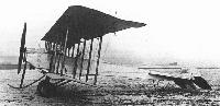
In 1913, the Coventry Ordnance Works received contract No. CP 40633/13 from the Air Department of the Admiralty for one seaplane. It was powered by a 160 hp Gnome rotary, and allotted serial number 54. The seaplane was fitted with wireless and allotted the call sign NO6 in August 1913. No record has been found of the aircraft in Service or ever being completed.
H.King Sopwith Aircraft 1912-1920 (Putnam)
From steam-cooling, direct fuel-injection and supercharging we must now pursue our essentially chronological narration; and in a technical context this is conveniently achieved by recalling that, in the present writer's earlier Putnam volume Armament of British Aircraft 1909-1939 it was shown that the Coventry Ordnance Works Ltd was best-known in the development of military aeronautics for its 37 mm guns. Yet this same company had an even earlier association with the design and construction of airframes - an association which had its beginnings in 1911, when the 'C.O.W.' absorbed the Warwick Wright concern, acquiring also the services of Howard T. Wright and W.O. Manning. The talents of these two men Manning in particular were evident in two biplanes that were built (under the Battersea railway-arches) for the Military Trials of August 1912; and in this Sopwith story these aeroplanes have a special place because T.O.M. Sopwith was the test-pilot for them both.
Though entered in the Military Trials as No.10, the first of the pair was otherwise known as the Wombus, the first three letters connoting Manning's involvement. This involvement was, in fact, more than a purely technical one, for it was Manning who occupied one of the side-by-side seats when Sopwith made the first ground tests and short flights; but the technical feature calling for special attention here (and certainly for study on Sopwith's part) was the 14-cylinder 100 hp Gnome rotary engine which - after steam-cooling and direct fuel-injection - afforded him experience with a geared powerplant. True, the Gnome itself lacked any built-in gearing; but a 2:1 reduction ratio was afforded by a chain drive. The high thrust line thus resulting allowed a propeller diameter of no less than 11 ft 6 in - a figure appreciably greater than the 10-ft diameter that characterised the Sopwith B.1 bomber of 1917. On one occasion the big chain-driven propeller of 1912 enabled Sopwith to carry not one, but two passengers though these had to sit on the bottom wing.
Sopwith's second C.O.W. responsibility was the testing and demonstration of another biplane - No.11 which had tandem seating and a Chenu water-cooled engine. There were frequent troubles with this aeroplane, as with its predecessor, and during August 1912 Sopwith set out for America on a second visit, to race not aeroplanes but motor-boats. He returned triumphantly in September.
M.Goodall, A.Tagg British Aircraft before the Great War (Schiffer)
Deleted by request of (c)Schiffer Publishing
COVENTRY ORDNANCE WORKS biplanes
This company took over the Howard Wright works at Battersea and hangar No.32 at Brooklands in late 1911, and manufactured two biplanes for entry in the Military Trials, due to start in August 1912. Howard Wright and W.O. Manning were responsible for the design and manufacture at Battersea, although Howard Wright resigned in the autumn when the first aircraft was complete. Although there was some similarity, there were also considerable differences between the two machines.
COW Military Trials biplane No.10
This was a side-by-side two-seater with rotary engine, with fuselage sides parallel in plan view to the tail. The fuselage was mounted above the lower wing, to which it was connected by struts enclosed in a fairing housing the main fuel tank. There was a wide gap between the top and bottom wings, which were connected by four pairs of interplane struts. The wings were tapered, with well-rounded tips and with considerable overhang to the top wing, which was braced to kingposts above the outer pair of interplane struts. The tail unit was unconventional, consisting of small twin fins and rudders and large fixed surfaces on either side of the fuselage. The two rudders and elevators were of similar part circular shape with aerodynamic balance areas. The undercarriage, with central skid, was not sprung and relied on the tires to absorb shocks. The top wing center section was cut away at the trailing edge after the machine's initial appearance.
Sopwith tested the machine at Brooklands from 5 May 1912 including the first week of the trials at Larkhill, when he was committed to leave to race in America for the Harmsworth Trophy for power boats. On one flight at Brooklands Sopwith carried three passengers, causing the machine to be nicknamed 'Wombus' (W.O. Manning's omnibus). Raynham flew the aircraft subsequently in the trials at Larkhill, where it was forced to withdraw for various reasons after a poor performance.
After the return of the machine to Brooklands, Manning, still with the company after Wright had left, redesigned the machine which flew in its modified form on 13 January 1913 for the first time. New four-bay wings of increased span and parallel chord were fitted and, as the gap was reduced, the fuselage rested directly on the lower wing. Inversely tapered ailerons replaced wing warping and larger elevators were fitted. A lengthened undercarriage maintained the propeller ground clearance. Later the chain drive was discarded and a smaller two-bladed propeller was fitted. The machine continued in use to the end of 1913.
Power: 100hp Gnome fourteen-cylinder air-cooled rotary, driving by Renolds chain and shaft at 2:1 reduction a 11ft 6in diameter two-bladed propeller.
Data 1st Version 2nd Version 3rd Version
Span top 40ft - 56ft
Span bottom 24ft 8in - -
Chord top 6ft tapering to 4ft 6in - -
Chord bottom 6ft tapering to 5ft 2in - -
Gap 8ft - -
Wing area 350 sq ft(1) - 630 sq ft
Tailplane span - 8ft 2in -
Elevators span - 11ft 9in 14ft 3 in
Area tailplane - 35 sq ft(2) -
Area elevators - 14sq.ft(3) 27.4 sq ft
Area fin - 4 sq ft -
Area rudder - 14sq.ft(4) -
Height rudder - 4ft. -
Length 33ft 3in - -
Height 12ft 8in - -
Weight 1,200lb - 1,100lb
Weight allup 1,950 lb - 1,900 lb
Speed range 20-60 mph - -
(1) Also reported as 337 sq ft. (3) Also reported as 17.3 sq ft.
(2) Also reported as 31 sq ft. (4) Also reported as 15.6 sq ft.
COW Military Trials biplane No.II
The second machine for the trials was a tandem two-seater with a water-cooled engine, and although of generally similar conception, varied from the first in many features. The fuselage was narrower and shorter but was still parallel in plan and was mounted higher in the wing gap. A similar center skid undercarriage had the addition of two skids behind the wheels. The wings were reduced in span and parallel with rounded tips and with skids under the wingtips. A single fin and rudder were fitted and both these and the tailplane and elevators were large and curvaceous in shape. The Chenu engine had a gear reduction drive and was cooled by radiators on either side of the fuselage.
This machine arrived late at Larkhill for the trials and did not fly owing to engine problems. It seems to have been abandoned soon after.
Power: 110hp Chenu six-cylinder inline, water-cooled driving by gearing at 2:1 reduction a lift 6in diameter four-bladed propeller.
Data
Span top 35ft
Span bottom 22ft
Tailplane span 10ft
Elevators span 13ft
Chord 5ft 6in
Gap 8ft
Area 290.5 sq ft
Tailplane area 35.8 sq ft
Elevators area 24 sq ft
Rudder area 10.8 sq ft
Length 31ft 3in
Rudder height 5 ft 3 in
Height 13ft 2in
Weight 1,250lb
Weight allup 2,050 lb
Max speed 68-70 mph
COW biplane seaplane
A tractor biplane seaplane was ordered from COW under Contract CP40688/13, to be fitted with a 160hp Gnome. It was allotted the RN serial number 54, but was never delivered, although it was still on order in September 1915. It was also listed to have an 80hp Gnome.
P.Lewis British Aircraft 1809-1914 (Putnam)
Coventry Ordnance Works Biplanes
During 1911, the Warwick Wright concern was absorbed by the Coventry Ordnance Works, Ltd., and its designers, Howard T. Wright and W. O. Manning, joined the new parent company. The decision was taken to enter the Military Trials scheduled for August, 1912, and two biplanes were designed by Wright and Manning and were constructed in the old Warwick Wright workshops under the railway bridge arches at Battersea.
Most of the metal components were fabricated at the main Coventry Ordnance Works plant, and the first machine, nicknamed "The Wombus", entered as No. 10 in the Trials and fitted with the fourteen-cylinder 100 h.p. Gnome engine, was ready for testing at Brooklands at the end of April, 1912. It differed in several respects from No. 11, its 110 h.p. Chenu-powered counterpart. The Gnome-engined No. 10 was given a broad fuselage which seated two side-by-side and which was untapered in the plan view. The side elevation, however, was of good streamlined form. The large 11 ft. 6 ins. two-bladed propeller was driven at 600 r.p.m. through a 2 : 1 reduction gear and Hans Renold chain, resulting in a high thrust-line, with the boss incorporating the refinement of a spinner. The twin rudders were mounted on fairly small fins, and were given upper and lower horn balances, the same balancing being applied to the elevators. The lower wings were joined to the fuselage through the medium of two pairs of struts and of a streamlined fairing which embodied the petrol tank. No centre-section struts were used, and the upper wings were borne solely by the four pairs of interplane struts, the unusually large gap of 8 ft. appearing between upper and lower planes to bestow a remarkably good field of view from the cockpits. Warping was used for lateral control, the control pulleys were faired, and sliding aluminium panels facilitated inspection of the wings. King-posts and wire-bracing supported the considerable overhang of the upper wing-tips. No springing was incorporated in the undercarriage; all shock-absorbing was undertaken by the large, soft, 6 ins. thick tyres.
The second machine, No. 11, carried its two occupants in tandem cockpits and consequently possessed a narrower fuselage than that of its companion. Between the rear cockpit head fairing and the tail, the fuselage was shortened by 2 ft. and it was set higher above the lower wings than that of No. 10, with a deeper support beneath it. The Chenu engine was water-cooled, its radiators being carried on each side of the cockpits. The tail unit differed also in having a single fin and rudder of unusual "shark's-fin" outline, and the main undercarriage was given extra vertical struts at the rear of each unit. No. 11's upper wings were 5 ft. shorter in span than those of No. 10, and the lower tips were fitted with skids. A four-bladed propeller was formed by superimposing a pair of two-bladed propellers.
No. 10 was flying very successfully at Brooklands for about two months before the Trials, for the purpose of which T. O. M. Sopwith had been appointed as the pilot of both machines. In the event, neither aircraft distinguished itself. No. 10 suffered from trouble with its large propeller, and the Chenu engine in No. 11 proved refractory, the machine flying very little.
After the fiasco of the Military Trials, the Gnome-engined No. 10 was rebuilt during the latter part of 1912. The original tapered wings were replaced by a new larger set with parallel chord and three bays provided by eight pairs of interplane struts. The unequal span was retained and, again, centre-section struts were not included. In its new form the C.O.W. biplane proved quite successful, and was flown at Brooklands during early 1913 by F. P. Raynham, who was able to land it at under 20 m.p.h.
SPECIFICATION
Description: Two-seat tractor biplane. Wooden structure, fabric covered.
Manufacturers: Coventry Ordnance Works, Ltd., Coventry, Warks., and at Battersea, S.W.II.
Power Plant: 100 h.p. Gnome (No. 10); 110 h.p. Chenu (No. 11).
Dimensions: Span, 40 ft. (No. 10); 35 ft. (No. 11). Length, 33 ft. 3 ins. (No. 10); 31 ft. 3 ins. (No. 11). Wing area, 350 sq. ft. (No. 10); 325 sq. ft. (No. 11).
Weights: Empty, 1,200 lbs. (No. 10); 1,300 lbs. (No. 11). Loaded, 2,000 lbs. (No. 10); 2,100 lbs. (No. 11).
Performance: Maximum speed, 60 m.p.h.
Jane's All The World Aircraft 1913
COVENTRY ORDNANCE. The Coventry Ordnance Works, Ltd., Coventry. London office: 28, Broadway, Westminster, S.W. Established 1912. Capacity: 50 machines a year without difficulty.
1912.
Model 10.
----------------------------------------------------
Length...............feet(m.) 29 (8.80)
Span.................feet(m.) 56 (17)
Area............sq. feet(m?.) 630 (58)
Weight, total......lbs.(kgs.) 1900 (861)
useful.....lbs.(kgs.) 800 (362)
Motor....................h.p. 100 Gnome
Speed, max........m.p.h.(km.) 60 (97)
min........m.p.h.(km.) ...
Endurance................hrs. ...
Number Built during 1912 .... 2
Remarks.--Experimental machines.
Журнал Flight
Flight, May 18, 1912.
THE COVENTRY ORDNANCE BIPLANE.
THE first impressions one gets of the New Coventry Ordnance Biplane are its marked originality, its excellence of design and construction, and its businesslike - more than that - its warlike appearance. It has a certain atmosphere about it that brands it as a machine intended for harder and more serious service than mere aerodrome work.
It was designed jointly by Mr. W. O. Manning and Mr. Howard Wright to fulfil War Office requirements. And from the tests that have already been carried out - it has lifted with perfect ease two passengers over its full complement, four persons in all, and that with the ignition of its 100-h.p. Gnome motor very much retarded, and with its extra passengers standing outside on the cellule, where they each were absorbing a considerable power in extra head resistance - we think we can safely predict that it will have no very great difficulty in showing itself to advantage in the military competitions.
Second impressions single out for notice the large gap of 8 ft. between the main supporting surfaces, the hugeness of the propeller, it measures eleven and a half feet from tip to tip, and the neatness of the landing gear, unsprung except for the resiliency that its large six-inch tyres afford.
A factor of safety of 12 has been worked to throughout, and probably it was the consideration of how to obtain that safety factor without having to resort to too much weight of material that influenced the designers in deciding to make their machine a double-decker.
It was built throughout at Howard Wright's original works at Battersea, with the exception of most of the metal work. This was turned out at the Coventry works.
The total area of supporting surface is, roughly, 350 square feet, this lifting its total load of about 2,000 lbs. all on, at its flying speed of 60 miles per hour - a loading of approximately 5 1/2 lbs. to the square foot. The upper and lower surfaces span 40 ft. and 20 ft. respectively, the chord in both cases diminishing from 6 ft. in the centre to 5 ft. at the tips. The extra span of the upper surface is made up by an extension on each side. These extensions are virtually complete monoplane wings braced to the rigid plane structure by king posts and steel cable on top, and by stranded steel cable below. They are arranged to warp for the correction of lateral balance. Both their tips and the tips of the lower plane are finished off like those of the Borel wing in order to obtain a very powerful warp. The warping is operated by stout stranded steel cables passing from the rear boom of one extension under stream-line pulleys on the lower plane, straight through to the pulley on the opposite side and up to the other extension. The operating-wires from the control-wheel are "tapped" on to this main cable, for by this arrangement the movements and jerkings that are produced in the main warping cable by the action of wind gusts on each warping surface, are communicated direct to the opposite wing-tip and not, as in many cases, via the control-wheel. This feature should also materially lessen the fatigue of the pilot when flying in anything of a strong wind. The warp-compensating wires on top pass over rocking king posts and down again under pulleys fixed just above the rear wing-spar.
For a biplane, the spars, of ash, are of very generous dimensions. They are 3 inches in depth and over an inch thick in both cases. The ribs are of spruce, and solid, except for the drilling in each to allow the internally fitted drift cables to pass. These drift cables are, by the way, of the same size solid core stranded steel cables as are used for taking the main lift.
The 8 ft. vertical struts separating the main planes are of silver spruce. Although they arc of a goodly size from front to back they are relatively quite thin. But this is compensated for by the fact that they are braced together in two sets of four. They fit into steel lugs where the cross-bracing cables are also assembled.
The planes are built and attached in sections, the attachments being arranged internally where they are accessible, and where they may be systematically inspected through neat aluminium sliding doors. There are eight of these - one against each strut socket.
The main body - wide enough to seat pilot and passenger side by side - is essentially a wedge-shaped box girder, flattening horizontally towards the rear. In its construction ash is employed for the main booms and spruce for the cross-members. Viewed from above its sides are parallel from stem to stern. Thus it is sufficiently wide at the tail to provide a good damping surface, a point which reduces the extra tail surface necessary. These surfaces are flat, and have a purely floating action in flight. In shape they are quarter elliptical. At the extreme rear, the sides of the fuselage extend above and below the top and bottom surfaces, forming small fins, to the back edge of which the vertical rudders are hinged. They, similarly to the elevators, are balanced in their action. A bent cane skid takes the weight of the after section of the machine when at rest on the ground. The main chassis wheels are so placed that there is only about 40 lbs. of weight at the extreme tail - a joy to its attendant mechanics - they most probably in their time have had to deal with machines tremendously tail-heavy when on the ground.
The engine mounting is decidedly interesting. The four body booms in front are assembled in a pressed steel housing, which accommodates both the motor - a 100-h.p. 14-cylinder Gnome - and the propeller shaft. The Gnome is slung low down in the housing and, keyed to its nose is a chain wheel, from which the drive is taken by a Hans-Renold chain - this alone weighs something like 25 lbs. - to the propeller shaft above. There is a reduction of 2 to 1 in the transmission. The propeller shaft is mounted, together with the engine in ball bearings, and two ball thrust washers are fitted - the larger to accommodate the propeller thrust and the smaller to take the negative thrust caused by the head resistance on the slow running or stationary propeller during a vol plane.
A peculiarity about the engine - we say peculiarity because we have never previously seen this system applied to a rotary motor - is that it is equipped with Bosch dual ignition, by which it may be started from the pilot's seat. Another refinement is the drip-catching funnel arranged beneath the carburettor, by which any overflow of petrol is collected and led through a copper pipe to the exterior of the body, where it is out of harm's way. A covering, similar to a Sizaire car bonnet cases in the motor and propeller-shaft housing. It is cut from sheet aluminium, and kept in place by ordinary car-hood fasteners.
The propeller is a colossal structure of teak with nine laminations. It is 11 ft. 6 ins in diameter, and rotates at 600 revs, per minute. It is noteworthy that, from the boss to a point 18 ins. along the blade it is designed to give no thrust, but merely for that section to travel through the air, causing as little head resistance and absorbing as little power as possible. In defence of this notion the designers ask two questions. - Firstly, why should the pilots sit in more draught than can be avoided? and secondly, what is the use of projecting that 3 ft. diameter column of air rearwards to impinge directly on the fuselage where it would cause a drag equal to or in excess of the thrust obtained from projecting it?
Regarding the landing gear we must certainly say that its simplicity appeals to us a great deal more than the weird and wonderful shock-absorbing devices that we occasionally see. It consists of a pair of 30-in. wheels - 6-in. tyres are employed - mounted on a common axle, which supports the machine through short struts of Honduras mahogany. No sideways movement of the machine on landing is provided for. Two wheels only are used. Three or more, if rigidly attached, would cause trouble, such as was experienced with the Astra triplane, if a landing were made on anything but the smoothest of grounds.
A single skid of hickory proceeds forward, supported by two struts in V of Honduras mahogany, to protect the propeller and front section of the machine.
From the cockpit the pilot and his passenger obtain a very clear view of the country directly beneath and all round them. The short span of the lower plane helped in this respect to a great extent.
Before the pilot is a wheel, mounted at the top of a vertical column. Warping is operated by twisting the wheel laterally, and the altitude is varied by rocking the column to and fro. A foot lever commands the twin rudders; at present only single control is fitted, but this will be duplicated shortly se that the passenger as well can take charge.
In front is a dashboard where are located the engine controls and the various gauges and instruments common to present-day aeroplanes.
The oil tank, holding 22 gallons, and an auxiliary gravity feed petrol tank, holding 10 gallons, are arranged just in front of the dashboard. The main petrol tank, containing 40 gallons of fuel, is stored away in the streamline well beneath the cockpit.
Flight, July 13, 1912.
THE MILITARY COMPETITION - THE MACHINES.
THE COVENTRY ORDNANCE BIPLANE.
As mentioned in our issue of last week, the Coventry Ordnance Works, Ltd., are entering a pair of machines for the War Office aeroplane competition. One of these has already been described in FLIGHT; the other is of the same type, but is fitted with a 110-h.p. Chenu motor in place of the 100-h.p. Gnome; it has 5 ft. less of wing span, and it is some 2 ft. shorter in overall length. Details and photographs of this latter machine we are not yet able to publish. In the meantime, however, let us briefly recapitulate the main characteristics of the 100-h.p. Gnome-engined machine that has been flying at Brooklands for some two months past. We print in this issue a series of photographs illustrating this highly interesting and original biplane. Its design is jointly due to Mr. Howard Wright and Mr. W. O. Manning, A.F.Ae.S. For its construction, most of the building was carried out at Mr. Howard Wright's works at Battersea, the metal work being done at the Coventry works.
Incorporating the fuselage as a feature of construction, it is a biplane of the tractor type. The body, of lattice-girder construction, flattening toward the rear, is sufficiently wide to seat pilot and passenger side by side. Its sides are parallel. In front, the four longerons are assembled into a specially designed pressed-steel housing, in which both the motor and the propeller-shaft are mounted. The drive to the propeller-shaft is by a Hans Renold chain, it being so arranged that the speed of rotation of the propeller is half that of the engine. The propeller itself is strikingly large, for it measures 11 ft. 6 in. from tip to tip, while in its construction nine laminations of teak are employed. It has the peculiarity that, from the boss to a point some 18 ins. down the blade, it is designed to give no forward thrust, but merely to revolve in air, causing as little resistance and absorbing as little power as possible. For this and other reasons, when the machine is flying, those in the cockpit notice comparatively little rush of air. As an advance on accepted practice, particularly relating to Gnome engines, the motor on this machine has been equipped with Bosch dual ignition in order that it may, when necessary, be started from the pilot's seat.
The main supporting surfaces are double surface, are unequal in span and are separated by a gap of 8 ft. The upper plane spans 40 feet, the lower 24 ft. 8 in. The chord in measurement diminishes from 6 ft. at the centre of the wings to 5 ft. near the tip. Both end sections of the top plane, each 10 ft. in length, are constructed so that they may be warped for the correction of lateral balance. As for the cross sections of the plane, the designers have made use of one that has been experimented with by M. Eiffel, for, data relating to its behaviour being available, it has been thought more advantageous to have something definite to work upon than to employ a section the virtues of which might be problematical. The landing gear is about as simple a conception as one could possibly cite. No shock absorbers have been introduced, all the shock absorbing necessary being done by large diameter 6 in. tyres. Protection is afforded against damage to the propeller by a turned up hickory skid, which proceeds forward and which is connected to the nose of the machine by a pair of struts of Honduras mahogany arranged V fashion.
A good idea of the tail is conveyed by one of our photographs. Tanks for the storage of fuel and oil are located under the bonnet. Here there is a tank for oil holding 32 gallons and one for petrol holding 10; the main balk of the petrol, however, is carried in a large tank arranged in the streamline well below the fuselage. From there to the auxiliary tank under the bonnet it is fed by pressure.
Main characteristics:-
Motor 14-cyl. Gnome, 100-h.p. rotary
Overall length 33 ft. 3 in.
Span 40 ft., 24 ft. 8 in.
Area 350 sq.ft.
Average chord 5 ft. 6 in.
Weight, all on 2,000lbs.
Speed 60m.p.h.
Flight, August 10, 1912.
THE MILITARY AEROPLANE COMPETITION - THE MACHINES.
THE CHENU-ENGINED COVENTRY ORDNANCE BIPLANE.
THIS machine differs very little from the 100-h.p. Gnome-engined biplane that we described in these columns quite recently. The main point of difference, besides the fact that a 110-h.p. water-cooled Chenu motor is fitted instead of a 100-h.p. Gnome, is that the fuselage is much narrower, being designed to accommodate the pilot and passenger in tandem. The main dimensions, too, are considerably smaller. A four-bladed propeller is employed.
Main characteristics:-
Overall length 32 ft.
Speed 68-70 m.p.h.
Span 32 ft.
Weight without complement or fuel 1,250 lbs.
Area 300 sq. ft.
 |
S.Ransom, R.Fairclough - English Electric Aircraft and their Predecessors /Putnam/
|
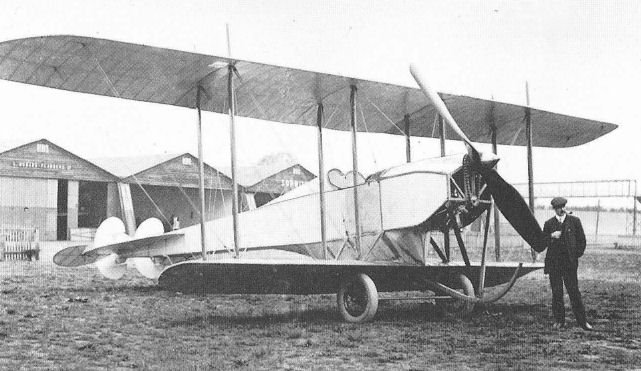
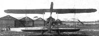
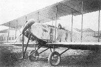
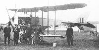
| COW's entry for the 1912 Military Trials, later given Trials No.10, making its debut at Brooklands in April. Note the early form of the wings without centre-section cut-outs.
|
 |
M.Goodall, A.Tagg - British Aircraft before the Great War /Schiffer/
|
| COW biplane No.10 (first version) with cutout in upper wing center section at Brooklands.
|
 |
S.Ransom, R.Fairclough - English Electric Aircraft and their Predecessors /Putnam/
|
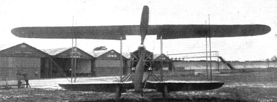
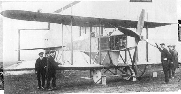
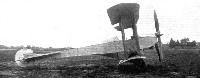
| Biplane No.10 at Larkhill in August 1912.
|
 |
Журнал - Flight за 1912 г.
|
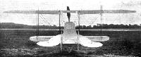
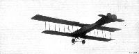
| THE COVENTRY ORDNANCE BIPLANE. - Side view.
|
 |
S.Ransom, R.Fairclough - English Electric Aircraft and their Predecessors /Putnam/
|
| Biplane No.10 at Brooklands. Note revised wing form.
|
 |
Журнал - Flight за 1912 г.
|
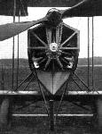
| The Coventry Ordnance biplane, as seen from in front.
|
 |
Журнал - Flight за 1912 г.
|
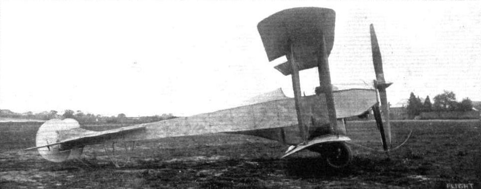
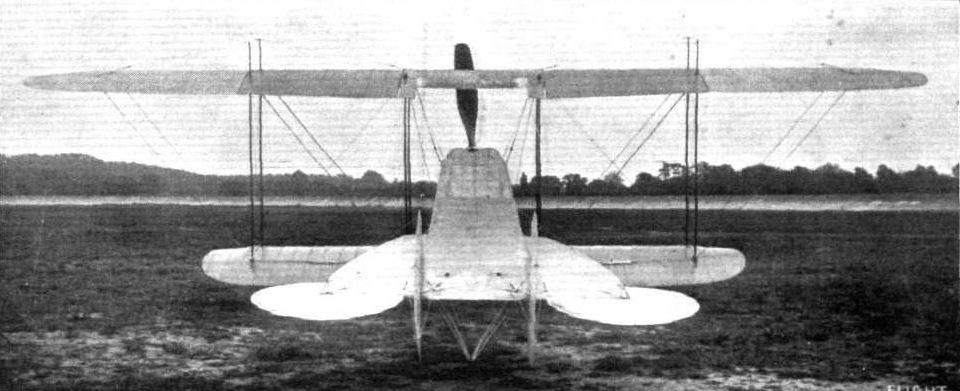
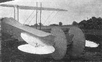
| The Coventry Ordnance biplane from the rear.
|
 |
Журнал - Flight за 1912 г.
|
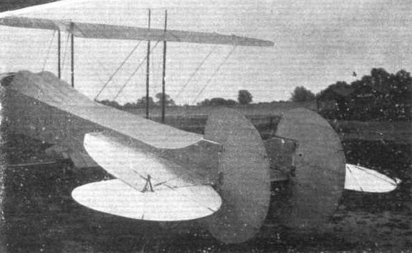
| THE MILITARY COMPETITION MACHINES. 5. The arrangement of the tail.
|
 |
Журнал - Flight за 1912 г.
|
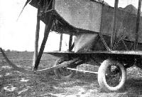
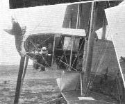
| Details of the front section of the machine, showing the engine mounting, the main hickory skid, and the unsprung landing gear.
|
 |
Журнал - Flight за 1912 г.
|
| Details of the front part of the machine, showing the housing for the 100-h.p. Gnome and the chain transmission.
|
 |
Журнал - Flight за 1912 г.
|
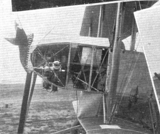
| THE MILITARY COMPETITION MACHINES. 7. The body with side casing removed, showing the 100-h.p. Gnome motor.
|
 |
Журнал - Flight за 1912 г.
|
| The stream-line encased warping pulley for the Coventry Ordnance biplane.
|
 |
H.King - Sopwith Aircraft 1912-1920 /Putnam/
|
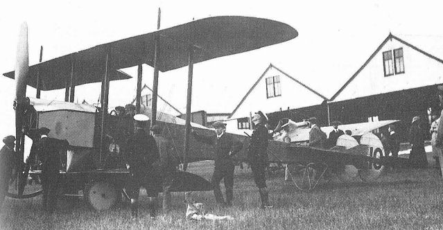
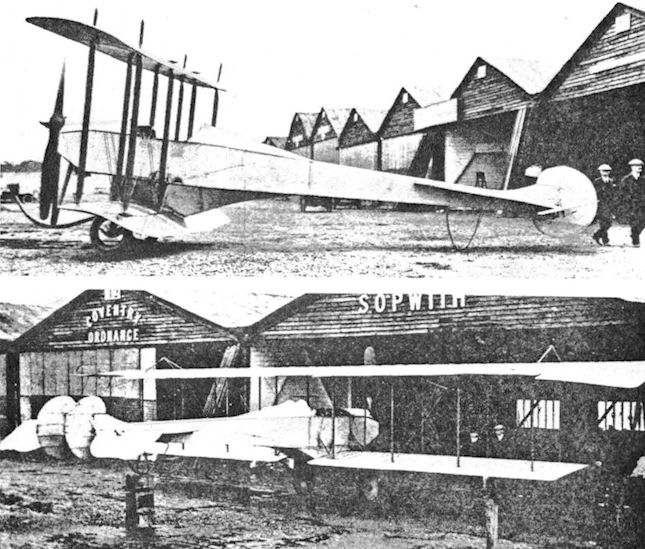
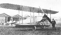
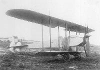
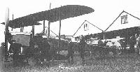
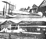
| For the Military Trials of 1912 Tom Sopwith acted as test pilot for the Coventry Ordnance Works respecting No.10 (the Wombus) shown in these two views, and No.11, later depicted. Note the names on the hangars in the lower of this pair of pictures, showing No.10 in rebuilt form.
|
 |
M.Goodall, A.Tagg - British Aircraft before the Great War /Schiffer/
|
| COW biplane (second version) with parallel chord wing.
|
 |
S.Ransom, R.Fairclough - English Electric Aircraft and their Predecessors /Putnam/
|
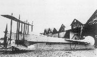
| Biplane No.10 Modified, Brooklands, January 1913.
|
 |
M.Goodall, A.Tagg - British Aircraft before the Great War /Schiffer/
|
| COW biplane No.10 (third version) with direct propeller drive.
|
 |
Журнал - Flight за 1913 г.
|
| The 100-h.p. Coventry Ordnance biplane, designed by Mr. W. O. Manning, has, since it has undergone general alterations and been fitted with more supporting surface, done quite a lot of flying at Brooklands of late. Mr. P. Raynham has been its pilot, and he flies it, most often, with a passenger up. The biplane has an unusually wide speed range, it being possible to land the machine at a less speed than 20 miles per hour.
|
 |
S.Ransom, R.Fairclough - English Electric Aircraft and their Predecessors /Putnam/
|
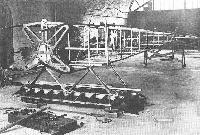
| Fuselage for Biplane No. 10 under construction at Battersea early in 1912.
|
 |
P.Lewis - British Aircraft 1809-1914 /Putnam/
|
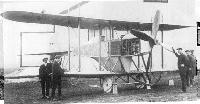
| COW biplane No.11. The second machine for the Military Trials with the unsatisfactory Chenu engine.
|
 |
S.Ransom, R.Fairclough - English Electric Aircraft and their Predecessors /Putnam/
|
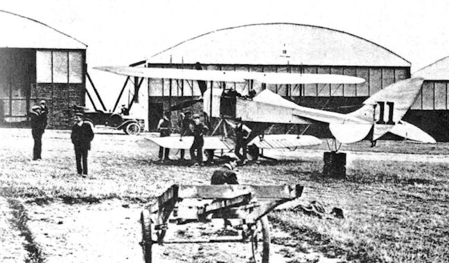
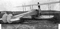
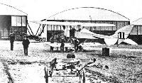
| Biplane No.11 with pilot and ground crew at Larkhill.
|
 |
H.King - Sopwith Aircraft 1912-1920 /Putnam/
|
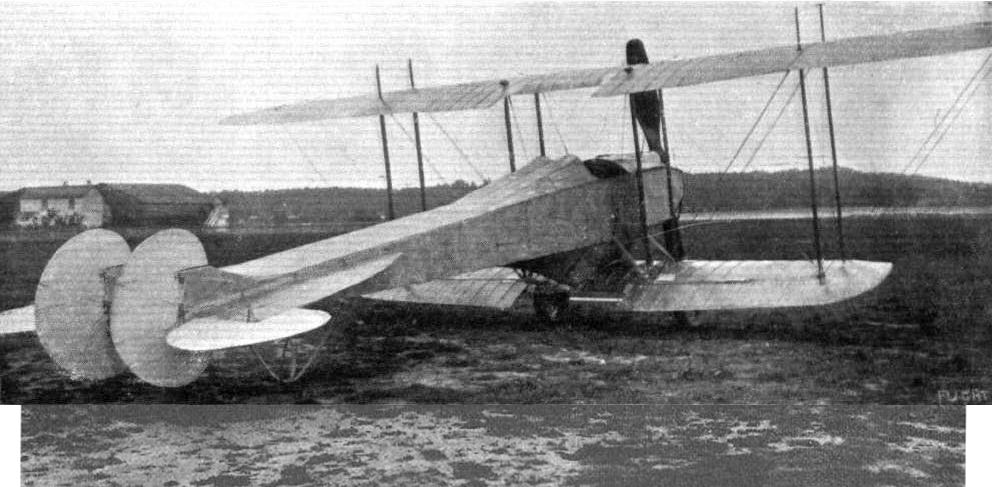
| The second of the two C.O.W. Military Trials biplanes which had Sopwith associations No.11, with Chenu engine and distinctive tail.
|
 |
Журнал - Flight за 1912 г.
|
| Detail of the Coventry Ordnance landing chassis, showing the small hickory skid intended to protect the chassis should anything happen to the wheels. The wheel is omitted to avoid complication.
|
 |
Журнал - Flight за 1912 г.
|
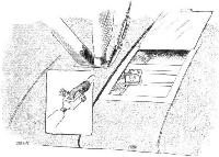
| One of the aluminium inspection doors fitted to the planes of the Coventry Ordnance biplane. The sketch shows the method employed for the joining of the wing sections. Inset is the quick release pin. These are used throughout the machine to minimise the time necessary (or dismantling and erection.
|
 |
Журнал - Flight за 1912 г.
|
|
|
 |
S.Ransom, R.Fairclough - English Electric Aircraft and their Predecessors /Putnam/
|
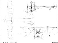
| Coventry Ordnance Works 1912 Military Trials Biplanes.
|
 |
P.Lewis - British Aircraft 1809-1914 /Putnam/
|
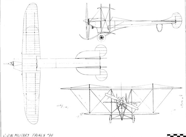
| C.O.W. Military Trials No. 10
|
 |
Журнал - Flight за 1912 г.
|
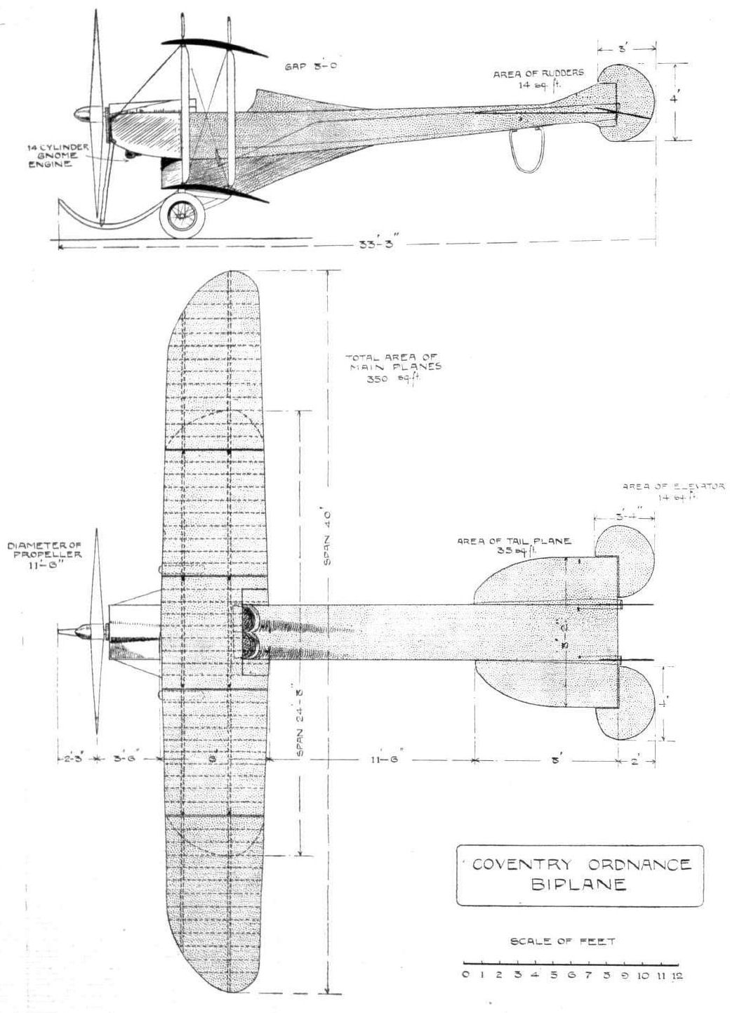
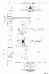
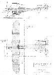
| THE COVENTRY ORDNANCE BIPLANE. - Plan and elevation to scale.
|