C.Barnes Short Aircraft since 1900 (Putnam)
Short Biplane No. 2
The second biplane designed by Horace Short was ordered in April 1909 by J. T. C. Moore-Brabazon, specifically for his attempt to win the Daily Mail’s prize of £1,000 for the first flight of one mile in a closed circuit by a British pilot in an all-British aeroplane. Moore-Brabazon had built himself a biplane as early as 1907, for which Short Brothers had manufactured various components, although they had no part in its design. When it failed to fly at Brooklands, on the meagre power of a single 12 hp Buchet engine, he abandoned it and went to France, where he bought three Voisins in succession, the third being the E.N.V.-engined Bird of Passage, which he brought to Shellbeach in the spring of 1909; on this he became the first Englishman to fly in England, at the end of April. The Daily Mail’s prize was announced just previously, on 7 April, and had to be won within one year from that date, so Moore-Brabazon was naturally keen to add to his laurels.
By this time Short Brothers’ works at Shellbeach were in commission and Horace Short had become familiar with the details of the Wright Flyer and indeed critical of some of its design features. It was by no means certain that any British engine of more than 30 hp would be available, but a 50-60 hp Green was ordered, although delivery from the Aster works, where they were being made, was at that time very slow. Moore-Brabazon had salvaged the Vivinus engine originally fitted to his second Voisin, and this was available for practice flights, although ineligible for competition, because of its Belgian origin.
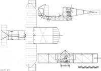
Short No. 2 incorporated a great deal of Wright practice, but differed in several important respects. The biplane wings and front elevators were somewhat similar to the Wrights’, but of higher aspect ratio. The chassis comprised a pair of strongly trussed girders shaped like a sleigh to ride across the Leysdown dykes in a forced landing; each girder consisted of upper and lower longerons, parallel below the wings but curved upwards at the front to meet at the elevator pivots, separated by nine vertical struts braced by diagonal steel strips in each bay, the strips being twisted so as to lie flat where they crossed each other. Like Short No. 1, both of No. 2’s propellers turned the same way, being driven by uncrossed chains. The elevators were of wide span and narrow chord and gap, with square tips, and incorporated a new type of camber-changing linkage (patent No. 23,166/09) which avoided infringement of the Wright patent (No. 16,068/09). The mainplanes were rigidly braced throughout their span, warping being replaced by differentially linked ‘balancers’, or mid-gap ailerons, for lateral control; these were of very low aspect ratio, and each comprised a pair of forward and aft ‘sails’ carried on a centre-pivoted boom mounted just above the middle of the outermost wing strut; the fabric of each sail was stretched on its frame by tension springs along the trailing edge so that the surface took up a camber appropriate to its angle of attack. The balancers were controlled by a centre-pivoted foot-bar with stirrups at each end, while the pilot had also two hand-levers, the right for the elevator and the left for the rudder, both moving fore-and-aft. The pilot’s seat was mounted on the lower leading edge to starboard, with the engine on the centre-line farther aft, leaving space for a passenger’s seat on the port side, if required. The single rudder was a tall narrow rectangle carried on short outriggers immediately aft of the elevator assembly, and a large vertical fin was carried by a pair of booms behind the wings. Horace Short was convinced that a large fixed fin surface in the slipstream was necessary to counteract yaw due to warping or aileron drag; he had argued unsuccessfully to this effect with the Wright brothers, who preferred their fixed keel area (‘blinkers’) forward and their rudders aft.
Short No. 2 was completed during September 1909, but the Green engine had not been delivered by then, so the Vivinus was installed for preliminary trials; in spite of being underpowered with this rather heavy engine, Moore-Brabazon succeeded in flying nearly a mile after being launched by derrick and rail on 27 September; he made a second flight of about 400 yards on 30 September, but landed heavily and damaged the port wing-tip. This was repaired, and the Green engine, which had just arrived, was installed, giving a larger reserve of power. Notice was given to the Daily Mail and the Aero Club that all was ready for the attempt on the £1,000 prize, and Lord Northcliffe sent Charles Hands to observe the flight; at once the weather became unsettled and remained so for a fortnight, but at last the day came; Moore-Brabazon rounded a mark-post half a mile away and landed back beside the starting rail, in an undulating flight varying in altitude from 20 ft to a few inches, but without actually touching the ground; he had won the prize, and the date was 30 October, 1909. This was two days before Charles Rolls made his first true flight on the first of the Short-Wright Flyers, and Moore-Brabazon could have claimed the David Salomans Cup also, but very sportingly waived his claim to it provided Rolls could himself qualify for it within one week, which he did. Moore-Brabazon’s prize-winning flight was followed by appropriate celebrations at Mussel Manor, during which he was challenged to take up a piglet to disprove the adage that ‘pigs can’t fly’; this he did in style on 4 November with a 3 1/2 miles cross-country flight outside the Shellbeach ground; on 7 January, 1910, he flew 4 1/2 miles from Shellbeach to the new flying ground at Eastchurch, after first winning the second of the Aero Club’s £25 prizes for an observed flight of 250 yards. Before leaving Shellbeach a larger cruciform tail, carried on four booms, had been fitted to No. 2, to improve stability for an attempt on the British Michelin Cup. Moore-Brabazon began practising in earnest for this competition, which closed on 31 March, 1910, and made four short flights on 12 February, followed by one of eight minutes on the 14th, carrying 20 gallons of petrol. All was ready for a serious attempt on 1 March, and he had covered 19 miles in 31 minutes before his crankshaft broke as a result of running continuously at maximum power. A spare engine was available and was fitted two days later, but then No. 2 was due to be exhibited on the Royal Aero Club’s stand at Olympia. After the show, No. 2 was taken back to Eastchurch, where the empennage was raised 21-in to a position level with the upper wing; Moore-Brabazon flew it once in this condition on 25 March, finding no improvement in control, but knew by then that nobody else with an all-British machine had a chance of beating his earlier performance, and in April he was adjudged the winner of the Cup; much longer distances had been flown by Rolls in his Short-Wright, but this was ineligible because of its French engine. After this Moore-Brabazon ordered one of the newer Farman-type biplanes that Horace had begun building after moving his works to Eastchurch and No. 2 was not flown again; there is an excellent 1/10 scale model of it in the Science Museum at South Kensington.
Span 48 ft 8 in (14-9 m); length 32 ft (9-75 m); area 450 sq ft (41-8 m2); loaded weight 1,485 lb (674 kg); speed 45 mph (72-5 km/h).
Short Biplane No. 3
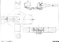
Like the Wright Type A, the Short No. 2 biplane was handicapped by its dependence on rail and derrick launching, quite apart from its general instability and unorthodox control system. Horace Short was well aware of these disadvantages and discussed them at length with members of the Aero Club at Mussel Manor. Late in 1909 he designed and built to Charles Rolls’ order an improved lightweight biplane, Short No. 3, which was completed in time for the next Olympia show in March 1910. It was much smaller than No. 2, although similar in layout, and had four wheels which could be held down below the skid runners for taxying and take-off, and retracted by springs before landing. The engine, a 35 hp Green, was mounted high up, with a direct-drive propeller, permitting the use of widely spaced booms to carry a fixed cruciform tail. Improved balancers with spring-tensioned fabric, as in No. 2, were operated by a right-hand lever with sideways movement only; the left-hand lever moved fore-and-aft to control the elevator, and there were foot pedals for direct control of the rudder, which was rubber-sprung to return to neutral if released. Thus the control system more nearly conformed to the single lever and rudder-bar system evolved by Esnault-Pelterie and popularised by Bleriot and Farman. The fixed tail comprised a low aspect ratio fin mounted centrally on a high aspect ratio tailplane, whose incidence could be adjusted on the ground through a limited range. The front rudder was larger than No. 2’s and the front elevators had no camber. Horace Short was anxious to find alternative means of lateral control at low speeds and took out several further patents for both leading-edge spoilers and trailing-edge intercostal vents or valves, to act as ‘lift dumpers’ on one side at a time. These are described in patents Nos. 2,613-5 of February 1910, but were not tested in flight, so far as is known. The chassis construction was generally similar to No. 2’s, with the same twisted-strip cross-bracing, and the wheel retraction device allowed the wheels to remain in use for landing if preferred, when they were sprung so as to bring the skids into play if the landing was too hard.
Five replicas of No. 3 were ordered even before the show opened, but in spite of its excellent workmanship, it was obviously out-of-date by comparison with the robust and uncomplicated Farman type, whose latest development by Roger Sommer had just been bought by Charles Rolls and was also on view. After the show ended, Rolls had only a few days to spare before taking part in the International Meeting at Nice, where he flew the French-built Wright on which he was killed at Bournemouth in July. When Short No. 3 failed to fly in its original form it seems that Rolls dismantled it and combined its chassis members with the wings, elevators and tail-booms of Short-Wright No. 6, as a prototype of his own design, called the Rolls Power Glider; this name indicates that he aimed to fly on as little power as possible at a low wing-loading. In the R.P.G. the 35 hp Green engine was installed on the starboard side, as in the Wright, but drove uncrossed Renolds chains, so that both propellers turned the same way; to compensate for the higher offset engine weight, the flat rectangular radiator was placed outboard of the port propeller shaft and was connected to the engine water jacket by long pipes. Apparently Rolls hoped to develop this contraption into a saleable article, but it was unfinished at his death, and the Wright components were retrieved by Short Brothers, who paid Rolls’ executors £200 for the dismantled No. 6, but could find no bidder for the remains of Short No. 3. The other five replicas of No. 3 were never started, and the only other aeroplanes built at Shellbeach were two designed by J. W. Dunne, one of them being Professor Huntington’s and the other the D.5 tailless biplane for the Blair Atholl Syndicate; it is not known whether these received Short constructor’s numbers, but the remaining c/ns up to 25 were not used, and a fresh start was made at Eastchurch with S.26, the first of the Short-Farman-Sommer boxkites.
Span 35 ft 2 in (10-7 m); length 31 ft (9 45 m); area 282 sq ft (261 m2); empty weight 657 lb (296 kg); loaded weight 860 lb (390 kg); estimated speed 45 mph (72-5 km/h).
M.Goodall, A.Tagg British Aircraft before the Great War (Schiffer)
Deleted by request of (c)Schiffer Publishing
SHORT biplane S2
Horace Short designed his second machine to Moore-Brabazon's order of April 1909, for a machine on which to attempt to win the Daily Mail Prize of ?1,000, for a circuit of one mile on a British aircraft flown by a British pilot. The aircraft was built at Shellbeach and was ready to receive the engine in September. For the initial trials a Belgian Vivinus engine was fitted, until the British-made Green became available in early October. However two flights were made with the heavy Vivinus, including one of nearly a mile on 27 September 1909. After repair of damage and fitment of the Green, Moore-Brabazon flew for a mile to win the prize on 30 October 1909. S2 was then flown successfully from Shellbeach to the new Short works at Eastchurch, a distance of four and a half miles, on 7 January 1910 and on 1 March 1910 flew nineteen miles in thirty-one minutes before the crankshaft broke. This flight won him the British Empire Michelin Trophy of 1910. The aircraft was exhibited on the Royal Aero Club stand at Olympia in March 1910.
Short S2 was a twin pusher biplane with three-bay wings outboard of the twin girder chassis. The wings were mainly parallel in chord, of higher aspect ratio than on S1 and with tips curving to a point, where a strut was provided to mount the 'balancers' for lateral control. These each consisted of two surfaces of different areas on an arm with a central pivot and these worked differentially controlled by foot pedals.
The main girder structure was carried upwards at the front to mount the biplane elevator with rudder mounted behind. A fixed tail was carried on wire braced top and bottom booms. In the early part of 1910 the tail was modified; twin booms tapering in side elevation, were fitted with a much extended fin and fixed tail surfaces.
The pilot sat on the leading edge of the lower wing on the starboard side of the centrally mounted engine with a space to port for a passenger; a pig was carried on one occasion for a wager to prove that pigs could fly! The single narrow radiator was later replaced by two of greater width and lower height on the lower wings in line with the chassis members.
Power:
32 l/2hp (?) Vivinus four-cylinder inline water-cooled reported 'to weigh 200 lb. more and give 15hp less than the Green engine'.
50/60hp Green four-cylinder inline water-cooled driving twin pusher propellers by uncrossed chains and shafts.
Data
Span 48ft 4in
Length 32ft
Area 450 sq. ft
Weight allup 1,485 lb.
Speed 45mph
P.Lewis British Aircraft 1809-1914 (Putnam)
Short No. 2
Built during August, 1909, for J. T. C. Moore-Brabazon, the Short No. 2 was used by him to win the Daily Mail ?1,000 prize for the first all-British circular flight of 1 mile on 30th October, 1909, at Shellbeach, Isle of Sheppey. When first flown in September the machine was fitted with a 30 h.p. Vivinus engine, but this was replaced with a 60 h.p. Green for the attempt on the prize. In 1910 a single propeller was substituted for the original pair, which were driven by chains. Span, 35 ft. 2 ins. Wing area, 450 sq. ft. Maximum speed, 45 m.p.h. Price, ?1,500.
Short No. 3
Following the successful performance of J. T. C. Moore-Brabazon's Short No. 2, a modified and improved version was ordered by the Hon. C. S. Rolls. The new pusher was ready for display at the 1910 Olympia Aero Show and, to the Short brothers' gratification, five were ordered before the exhibition was opened.
The No. 3 was still on original Wright brothers' lines, but differed in several important respects, incorporating alterations dictated by the operating experience of the previous year at Shellbeach and Eastchurch. Although smaller and lighter than its predecessors, the No. 3 was very strongly built. To enable it to take-off without the aid of a starting rail, retractable wheels were fitted, one of the earliest examples of such a device. On being tripped by the pilot they were withdrawn above the lower skid level by springs, the machine landing on the skids. The two chain-driven propellers used on previous Shorts were superseded by a single Short-built propeller of 7 ft. 6 ins. diameter, driven by a 35 h.p. Green engine. Control was effected by biplane elevators in front, with the rudder immediately behind them. A fin and tailplane were carried some distance aft of the wings, and balancers acting as ailerons were mounted on each side between the upper and lower wing-tips.
SPECIFICATION
Description: Single-seat pusher biplane. Wooden structure, fabric covered.
Manufacturers: Short Brothers, Eastchurch, Isle of Sheppey, Kent. Power Plant: 35 h.p. Green.
Dimensions: Span, 31 ft. 8 ins. Span (including balancers), 35 ft. 2 ins. Length, 31 ft. Wing area, 282 sq. ft.
Weights: Empty, 657 lb. Loaded, 857 lb.
Price: ?650.
Журнал Flight
Flight, October 2, 1909
Mr. Moore-Brabazon's Success.
ALL interested in the cause of aviation in Great Britain will join in congratulating Mr. J. T. C. Moore-Brabazon on the success he is meeting with in his experiments with his new British-designed-and-built biplane. It has been built by Messrs. Short Brothers, and is similar to the machine which was exhibited by them in skeleton form at the Olympia Show, the designer being Mr. Horace Short. In spite of the fact that he was handicapped by using a heavy motor car engine, Mr. Moore-Brabazon easily flew a mile in a semi-circular direction on Monday last and he intended to compete for the 250 yards, the half mile, and mile prizes offered by the Aero Club on Thursday of this week. When Mr. Brabazon has his new "Green" engine, which weighs about 200 lbs. less than the present motor, he is confident that he will make up all time lost in waiting for his present machine.
Flight, October 9, 1909
Mr. Moore-Brabazon's Progress.
ON Thursday of last week Mr. Moore-Brabazon did not meet with quite so great success as he obtained three days previously, and the longest distance flown was 400 yards. As the result of a sudden landing the machine was slightly damaged. We are able to give several views of this machine this week which give a good idea of its general appearance and clearly illustrate its characteristic features. We were fortunate in securing a snap of the machine during one of its brief flights last week, and this forms the frontispiece for the current issue. Mr. Moore-Brabazon has entered for the Daily Mail prize of L1,000 for the first British aviator on an all-British machine, covering the circular mile; as soon as he can get his new Green engine installed he will make an attempt for the prize, and there seems every likelihood of it being annexed very shortly now.
Flight, November 6, 1909
FLYING AT THE AERO CLUB'S GROUNDS, SHELLBEACH.
L1,000 "All British" Prize "Won.
AT last a flying machine, entirely constructed in Great Britain, has flown for a mile out and home, and no doubt this will go a great way in stimulating interest in the home product. It was on Saturday last that Mr. J. T. C. Moore-Brabazon succeeded in fulfilling the conditions of the Daily Mail L1,000 prize for the first circular mile flown on a British machine, and his mount was the Short biplane with which he has been experimenting for some time at the flying ground of the Aero Club at Shellbeach. Our readers will remember that this machine was fully illustrated in our issue of October 9th, and from the photograph which we publish in this issue it will be seen that although the machine is in some respects similar to the Wright flyers, considerable differences are conspicuous. Instead of the wings warping, stability is effected by small supplementary planes pivoted between the extremities of the main planes; the main planes are rigid; the rudder is placed in front, while the trailing vertical plane is fixed; the skids are quite different, and the two propellers revolve in the same direction instead of opposite. The motor fitted to the machine was a 50-60-h.p. Green, which has a bore and stroke of 140 by 140 mm., and weighs without fly-wheel and magneto about 250 lbs. It is quite fitting that this success should fall to Mr. Moore-Brabazon, for he was one of the first Englishmen to turn serious attention to flying. After experimenting with a machine of his own design for some time, he purchased a Voisin, on which he made one or two short flights. At the Aero Show at Olympia last spring he ordered the British-built machine from Messrs. Short Brothers, with which he has now met with such gratifying success.
Flight, March 12, 1910
THE SECOND OLYMPIA AERO SHOW.
AEROPLANES.
Short.
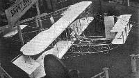
A BRITISH-BUILT biplane of special light design, and fitted with a 30-35-h.p. 4-cyl. Green engine. A feature of the design is the patent front elevating rudder, while another special detail is the arrangement of spring tension balancing planes. The lifting surface of the machine is 270 sq. ft., while the weight complete is 700 lbs. A similar machine is also exhibited by Mr. J. T. C. Moore-Brabazon on the Royal Aero Club's stand.
Flight, March 19, 1910
THE NEW "SHORT" BIPLANE.
Leading Particulars of the Short Biplane, 1910 Model.
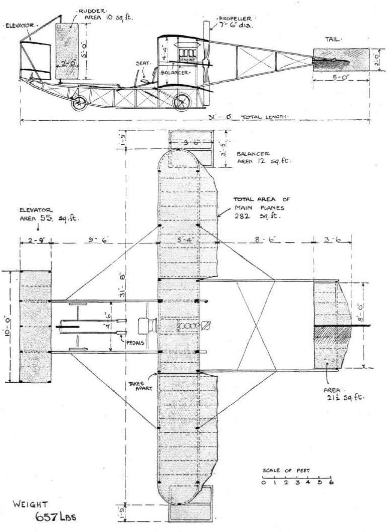
General Dimensions.-Areas-Main planes, 282 sq. ft.; fixed tail (hor.), 21 1/2 sq. ft.; (vert.), 10 sq. ft.; elevator, 55 sq. ft.; rudder, 10 sq. ft.
Lengths.-Span, 31 ft. 8 in., chord, 5 ft. 4 ins. (aspect ratio, 6) ; camber, 3 1/4 ins., situated about 24 ins. from leading edge; leverage of rudder, about 8 ft. 6 ins. from leading edge of main planes; gap, 4 ft. 4 ins. ; overall length, 31 ft.
Materials.-Timber, spruce; fabric, North British Rubber Co.
Engine.-35-h.p. Green.
Propeller.- Make, Short ; diameter, 7 ft. 6 in.; material, spruce.
Weight.-Machine, 390 lbs.; engine, 225 lbs. ; driver, oil, petrol, 200 lbs.; radiator, tanks, piping, 42 lbs. ; total flying weight, 857 lbs. ; loading (all weight supported on main planes) 3 lbs. per sq. ft.
Speed of Flight.-45-50 m.p.h.
System of Control.-Balancing planes, elevator, rudder.
Price.-L650.
THAT fact which above all others makes the new Short biplane interesting, is that its design is the outcome of actual experience in flight. During the last twelve months, Short Brothers have been collecting information from the practical aviation that has been actively in progress at Eastchurch and Shellbeach, which has proved invaluable to them, and it may be said that all their experience to date is embodied in the design and construction of this latest machine that they have developed. What makes it even more interesting, is that this machine is by no means radically different from the larger biplane with which Mr. Moore-Brabazon won the Daily Mail prize. That flyer was the first of the Short models to be actually flown, and the similarity between the two seems to us to be good cause to compliment the firm on the success that attended the scientific thoroughness with which they went to work in the first instance.
Leading Characteristics.
The latest Short biplane is characterised by its apparently massive construction, yet on examining it more closely it will be seen how scientifically the bulk of the material has been disposed. That this is the case is proved by the low actual weight of this machine, the framework and fabric weighing only 390 lbs. One fact that has stood out among all others as the result of practical experience is the absolute necessity for making the chassis portion of the machine and the engine bearers as strong as possible. These are, pre-eminently, the massive parts of the new Short biplane.
The chassis itself is a particularly interesting and very simple piece of work, consisting of a pair of lattice girders forming landing skis. These members owe their rigidity mainly to the fact that they are not very deep, and it is in fact a characteristic of the machine, distinguishing it from the majority, that the lower deck is very close to the ground when the machine is on the earth. Short Brothers regard this as a most important feature of their design, their experience having taught them how difficult it is to construct a high chassis that is sufficiently rigid to stand the terrific severity of the shocks to which it is likely to be subjected by beginners, who are sometimes apt to suddenly "drop" their machines from a height of possibly ten feet straight on to the ground.
Centre of Gravity.
Another outstanding characteristic of the Short design in this particular model, is the position of the engine midway up the gap, instead of being supported on the lower deck as is the more common practice. This position has resulted from the desire to have a low chassis and a single direct driven propeller of large diameter, but it seems to us that there is even a theoretical advantage in placing the engine in this position resulting from its tendency to raise the centre of gravity.
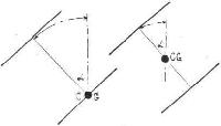
In any biplane there must be two main centres of pressure and resistance as the result of using two planes a considerable distance apart. Commonly the disposition of the principal masses locates the centre of gravity nearer to the lower centre of pressure than to the upper, with the result that it probably increases the inertia factor that militates against lateral stability, and also gives rise to the phenomenon of "kick up" that may occur when the engine is stopped in flight. Both the effects are probably caused by inequality in the leverages forming the couple represented by the two principal centres of pressure about the centre of gravity. The phenomenon of "kick up," which consists of an upward tilting of the front part of the machine automatically resulting from an interruption of the drive in flight, is a manifestation of the superior leverage of the centre of resistance of the upper plane, or it may be regarded as the more direct action upon the lower plane of the momentum of the principal mass - which comes to the same thing.
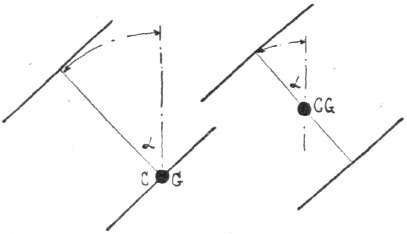
In respect to the matter of lateral stability mentioned above, it seems as if any position of the centre of gravity that is not coincident with the resultant of the two principal centres of pressure - which position is, presumably, midway in the gap - must be regarded as ascentric and, therefore, as possessed in some degree of the inertia factor that is generally recognised as detrimental to the stability of any such system.
This latter point has not yet been thoroughly discussed, and it would be helpful if some such attention as our readers recently gave to the principle of the dihedral angle, which we broached in our description of the Antoinette monoplane, were devoted to a discussion of the centres of pressure and centre of gravity in biplanes. Diagrams are given herewith to facilitate reference, and the point to which special attention is drawn is that the inertia to recovery on the part of a system in which the centre of gravity is located on the lower plane is greater than when the centre of gravity is located midway in the gap, owing to the fact that the inertia of a mass is proportionate to the square of its radius from the centre of rotation.
(To be concluded.)
Flight, March 26, 1910
THE NEW "SHORT" BIPLANE.
(Continued from page 213.)
Short-Wright Comparisons.
ALTHOUGH there are some points in common between the Short machine and the Wright machines that are manufactured in England by Short Brothers, the design in general is entirely different. The rudder, for instance, in the Wright biplane is placed behind; in the Short biplane it is placed in front where it is situated immediately behind the elevator. The Short biplane, too, has a horizontal and a vertical tail, whereas the Wright flyer has nothing but its double rudder at the rear of the planes. These differences are, of course, of a fundamental character, and entirely outweigh such small features of similarity as may be noticed in the appearance of the decks. The system of control, too, is fundamentally dissimilar, inasmuch as the planes of the Short machine are rigid, whereas those of the Wright are capable of being warped. Lateral equilibrium in the Short biplane is maintained by the manipulation of a pair of independent balancing planes that are pivoted to the vertical struts at the extremities of the machine.
In detail, as in generalities, the Short biplane is most interesting, and it gives evidence everywhere of most careful and original thought in its construction, as will be shown by a glance at the accompanying illustrations and a perusal of the following brief description of the more characteristic features of the machine.
Main Planes.
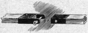
The main planes are so erected that they can be dismantled in three sections and packed fore and aft into a width of 10 ft., the principal transverse spars are jointed on either side of the central portion that forms a permanent part of the chassis. The joint is a simple socket and the fastening is accomplished by a single bolt, the strain being, of course, taken off the joints by the diagonal wire bracing that converts the construction of the decks as a whole into a lattice box-girder. Between the main spars are placed the cambered ribs upon which the surfacing material is stretched. The planes are double surfaced, that is to say the fabric is applied to the upper and lower faces of the ribs.
The Leading Edge.
The front spar of each deck forms the leading edge and is quite blunt; in fact, it is only rounded off at the corners, no attempt whatever having been made to provide a sharp entry, Short Brothers having been led to the conclusion, as the result of their experience, that there is no practical advantage in such a refinement. This is, of course, a very interesting and important point, because not only is it common opinion that the entering edge should at least be well rounded, but many constructors have gone to the trouble of continuing the ribs beyond the front spar in order to provide a really sharp entering edge without reducing the section of that member. It has always seemed to us that while a sharp entering edge may be advantageous in theory, the difficulty is to ensure that the machine shall fly with that edge tangential to the relative wind, in other words we are of the opinion that while the sharp cutting edge is probably best in one particular position it is quite likely to be less efficient than a blunt edge in other positions than that for which it was designed. Information on the subject of the actual behaviour of the air in the vicinity of the leading edge is very limited, and it would be interesting to know whether there may not be some sort of piling-up action taking place in the air itself of such a character as to give a blunt leading edge an artificial sharpness that automatically adjusts itself to the attitude of the machine in flight. Whether or no there is any justification for any such view, or whether the actual differences in efficiency between the theoretical streamline section and the blunt edge are far less than have been supposed we do not know, but it is, at any rate, very interesting to find how little attention is bestowed to the sharpening of the edges of struts and spars in the Short biplane.
Struts and Ties.
The struts themselves, like the main spars, are made of spruce, and are rectangular in section. They taper from the centre towards each extremity in order to combine strength with lightness, and they are mounted in manganese-steel sockets. These sockets are attached to the spars and not to the struts; in fact, there is no metal fitting on the struts at all, and if a strut should be broken another can immediately replace it. Being in compression as the result of the tension of the diagonal tie-wires, the struts are automatically prevented from coming out of their sockets; moreover, with this system of construction something of the flexibility that characterises the Wright joint has been retained, without the complication of the hook and eye. The tie-wires on the Short machine are stronger than was formerly considered necessary, 10 and 12 S.W.G. being the gauge that is now employed, whereas 16 used to be considered heavy enough.
It is interesting to note that Short Brothers have come to the conclusion that wires offer less resistance than is popularly supposed to be the case. Some of our readers may remember that Esnault-Pelterie publicly stated how, after having tried a Wright type of glider of his own construction, he abandoned the biplane principle in favour of the monoplane system solely because of excessive head resistance caused by the wires necessary in biplane construction. He attributed this resistance to the vibration of the wire and seemed to be distinctly of opinion that a single wire had resistance equivalent to a rigid strut an inch or more in diameter.
Chassis and Suspension.
The chassis forms another example of the lattice box-girder type of construction, four spruce beams being trussed together by vertical struts and diagonal ties. The tie-members between the upper and lower beams on each side are formed by strip manganese-steel, while the crossties between the side-members are formed by piano wire. The lower beams form the skis on which the machine lands, but in conjunction therewith a set of wire wheels are also provided in order to enable the machine to run about on the ground for starting. Two of these wheels, which carry the greater part of the load, are so mounted that they can be raised out of action by a small lever near the pilot's seat, as soon as the machine is in flight, thereby relieving them of all shock when landing. This releases a set of supplementary springs, which raise the wheels out of action above the level of the skis. The forward wheels, which merely serve to support the weight of the elevator and rudder, are suspended by elastic, and thus offer very little resistance to shock.
(To be concluded.)
Flight, April 2, 1910
THE, NEW "SHORT" BIPLANE.
(Concluded from page 229)
Supplementary Surfaces.
THE supplementary surfaces on the Short biplane consist of a biplane elevator, mounted on the front end of the chassis, a single vertical rudder situated immediately behind the elevator, and a fixed horizontal and vertical tail carried by a triangular outrigger behind the main planes. The horizontal member of the tail is cambered and is so mounted that its angle of incidence can be adjusted, but not while in flight. Even under normal conditions it is intended that this angle shall have a slight positive value, but the tail is not regarded as a load carrying member of the machine. The elevator has flexible surfaces so arranged that the pilot can camber them to give a positive or negative lift as may be required for the purpose of maintaining equilibrium or altering the attitude of flight. In its fundamental idea, this flexing of the elevator follows a principle introduced by Wright, but there are important differences in construction between the elevators of the two machines, notably in the fact that the planes of the Short elevator flex from the leading edge, which forms the fixed member of the structure.
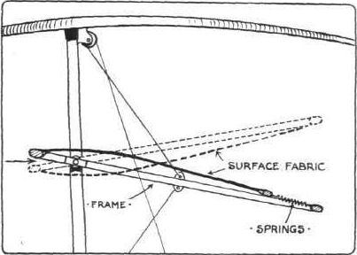
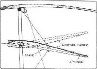
Two other supplementary surfaces are provided at the extremities of the main planes. These consist of pivoted balancing planes for maintaining lateral equilibrium. Their construction embodies a recent patent and is particularly ingenious, inasmuch as the plane consists merely of a horizontal sheet of fabric stretched between two spars by the action of springs joining the trailing edge of the fabric to the rear spar.
A fore and aft spar joins the two transverse spars and serves as a means of attachment to one of the vertical struts between the main planes. Provision is made for tilting these balancing planes either to a positive or negative angle, and owing to the method of mounting the fabric the planes automatically assume a camber as the result of the air pressure.
Control.
Control of the Short biplane is effected by means of two levers and a pair of pedals. The lever held in the pilot's left hand operates the elevator by a simple to and fro movement. The lever held in the pilot's right hand controls the lateral equilibrium of the machine by movements of the balancing planes. The pedals operate the rudder, which is normally held in a straight-ahead position by the action of elastic springs.
The coupling up of the right hand lever to the balancing planes is such that the pilot pushes the lever away from him when the right hand extremity of the machine is tilted above its proper level. It will be observed that the head resistances of the two balancing planes are equal to one another for any angle, consequently the machine does not tend to swerve from a straight path as the result of their use, and there is no need to employ the rudder in order to keep the course, as is the case with wing warping.
The Engine and Propeller.
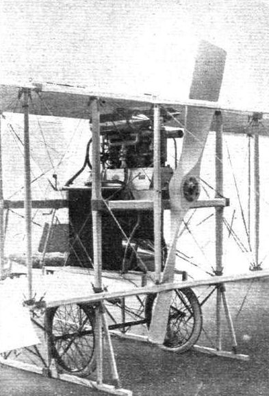
The engine on this machine is a four-cylinder 35-h.p. Green motor having a bore and stroke of 105 by 120 mm. and is mounted on two wooden girders that pass fore and aft between a couple of massive transverse girders bolted to four of the vertical struts between the main planes. The engine, as we have already pointed out, is raised above the lower deck so that the axis of the crank-shaft lies about midway in the gap. The two-bladed wooden propeller is direct-coupled to the crank-shaft. The petrol-tank lies just above the lower deck between vertical radiators on either side. Owing to the position of the engine it has been possible to fit a starting-handle on a swiveiling-bracket so that the engine can be started without handling the propeller, a refinement that is commendable, for the use of the propeller as a starting-handle unquestionably involves an element of danger that should be unnecessary.
Flight, April 9, 1910
THE SHORT CONTROL.
Referring to your recent description of the new Short biplane, could you give me further particulars relating to the exact arrangement and method of operating the vertical rudder, which I notice you state is controlled by foot ?
Liverpool. JAMES K. CHAPMAN.
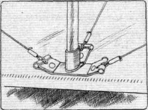
[The accompanying sketch clearly illustrates the method of mounting and controlling the rudder on the Short biplane. The rudder is situated immediately behind the elevator, and is attached to a vertical post that passes through the rudder plane a short distance behind the leading edge, and, therefore, approximately through the centre of pressure for small angles. The lower end of the rudder-post carries a cross-bar to which two rods are pivoted. These rods are hinged at their other extremities to a pair of hinged pedals. The cross-bar on the lower end of the rudder-post is tied by elastic springs to the side-members of the chassis frame; consequently, the rudder has a normal straight-ahead position, to which it automatically returns of its own accord. Although the elastic springs are sufficiently strong for this purpose, they do not interfere with the delicacy of the control.-ED.]
 |
Журнал - Flight за 1909 г.
|
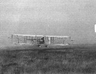
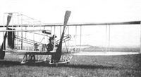
Mr. J. T. C. Moore-Brabazon in flight last week, at the Aero Club's Shellbeach Aerodrome, on his new all-British biplane, constructed by Messrs. Short Brothers.
J T C. Moore-Brabazon flying the Vivinus-engined Short No. 2 on which he won the "Daily Mall" L1,000 Prize on Saturday last at Leysdown late in September 1909.
|
 |
C.Barnes - Short Aircraft since 1900 /Putnam/
|
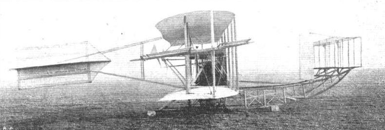
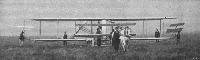
| J. T. C. Moore-Brabazon flying Short No. 2 at Leysdown in November 1909 after the Green engine had been installed.
|
 |
Журнал - Flight за 1909 г.
|
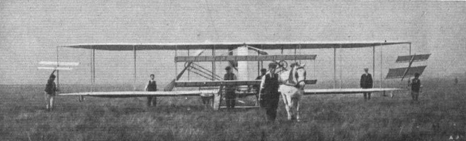
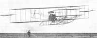
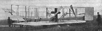
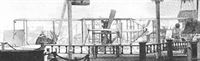
| Mr. J. T. C. Moore-Brabazon's new biplane, designed and constructed by Messrs. Short Bros., with which he has been making his flights at Shellbeach, being brought up to the starting rail after a flight.
|
 |
Журнал - Flight за 1909 г.
|
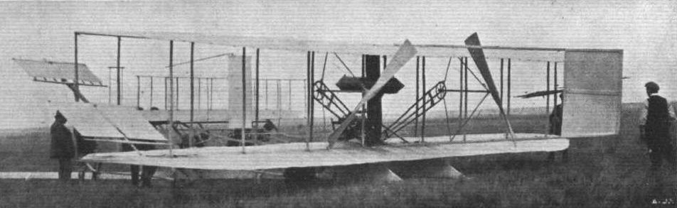
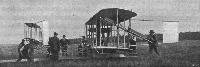
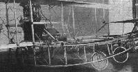
| Three-quarter view, from the back, of the Short biplane, constructed for Mr. Moore-Brabazon.
|
 |
Журнал - Flight за 1909 г.
|
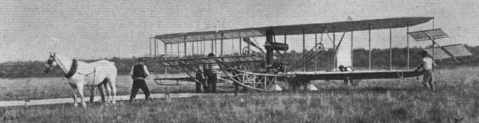
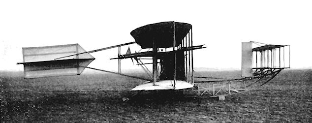
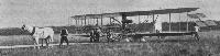
| Getting Mr. Moore-Brabazon's Short biplane in place on to the starting rail. The Short No.2, fitted with, a Green engine, with which J. T. C. .Moore-Brabazon won the L 1,000 Daily Mail prize for a circular flight of one mile.
|
 |
Журнал - Flight за 1909 г.
|
| Short S.2 on which Moore-Brabazon won the Daily Mail prize for a circular flight of one mile in October 1909.
|
 |
C.Barnes - Short Aircraft since 1900 /Putnam/
|
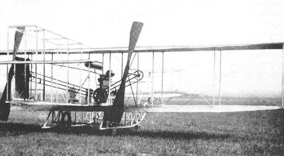
| The Rolls Power Glider constructed by combining the wings and control surfaces of Short-Wright No. 6 with the chassis and engine of Short No. 3, at Eastchurch in May 1910.
|
 |
Журнал - Flight за 1910 г.
|
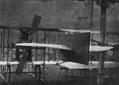
Short S.2 the final version with extended tail.
Mr. Moore-Brabazon's "No. 5," being his all-British "Short" biplane, in which the most noticeable alteration since we published a photograph of this machine, on October 9th last, is the tail.
SHORT (1910). The first machine to Short's own design. (The tail here shown is a specially large one fitted by Moore-Brabazon).
|
 |
P.Lewis - British Aircraft 1809-1914 /Putnam/
|
| Short No. 2 with enlarged empennage (inscribed ‘J. T. C. Moore-Brabazon No. 5’) at Eastchurch early in 1910.
|
 |
Журнал - Flight за 1910 г.
|
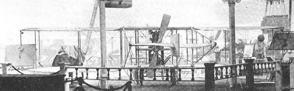
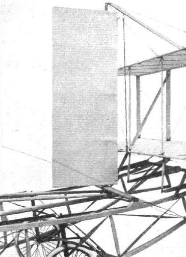
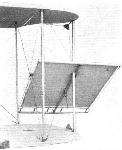
| General view from above of the new Short biplane, with fixed tail, front rudder, and balancing-planes among the special features.
|
 |
C.Barnes - Short Aircraft since 1900 /Putnam/
|
| View of the elevator and rudder on the Short biplane.
|
 |
C.Barnes - Short Aircraft since 1900 /Putnam/
|
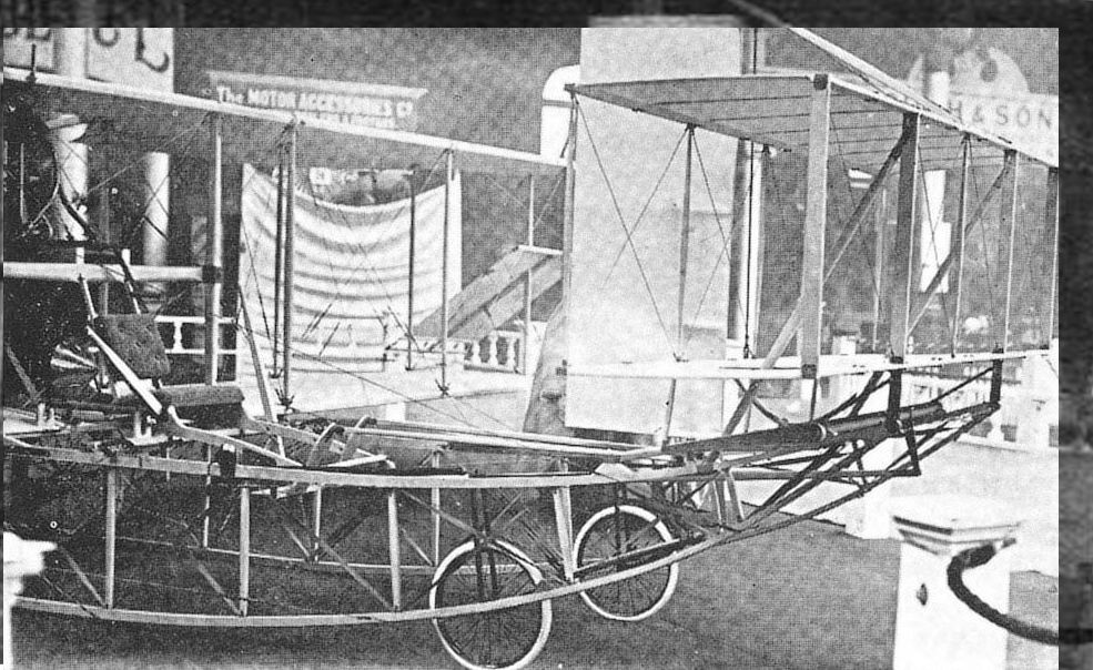
| View of Short No. 3 as shown at Olympia in March 1910.
|
 |
Журнал - Flight за 1910 г.
|
| View of the tail on the Short biplane.
|
 |
Журнал - Flight за 1910 г.
|
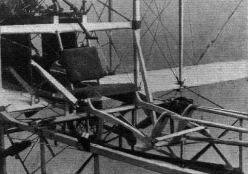
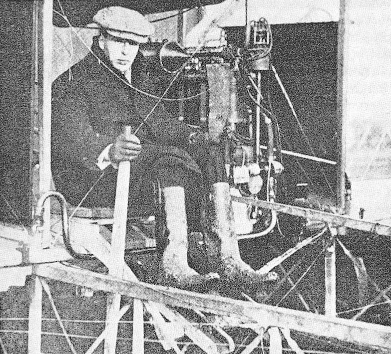
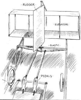
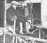
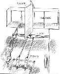
| View of the pilot's seat on the Short biplane. The lever on the pilot's right controls the balancing-planes, that on his left the elevator; the pedals control the rudder.
|
 |
Журнал - Flight за 1910 г.
|
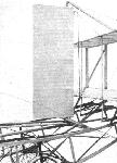
| View of the chassis on the Short biplane; the wheels are suspended on helical springs that are wound up by a ratchet-pawl device. The pilot releases a catch when he has ascended in the air and the wheels are drawn up above the level of the skis, upon which the machine therefore lands direct.
|
 |
Журнал - Flight за 1910 г.
|
| View of one of the balancing planes on the Short biplane. The fabric is stretched between the leading and trailing edges by a series of springs, which allow it to take its own camber from the wind pressure.
|
 |
Журнал - Flight за 1910 г.
|
| View of the rudder, which is situated in front, on the Short biplane.
|
 |
Журнал - Flight за 1910 г.
|
| View of the engine and propeller on the Short biplane. The engine is mounted high up in the gap
|
 |
C.Barnes - Short Aircraft since 1900 /Putnam/
|
| J. T. C. Moore-Brabazon on Short No. 2 in November 1909.
|
 |
Журнал - Flight за 1910 г.
|
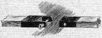
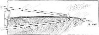
| Diagram illustrating the comparative movement caused by a cant at equal angular displacement when the centre of gravity is on the lower deck and midway in the gap.
|
 |
Журнал - Flight за 1910 г.
|
| Sketch illustrating the action of the balancing planes on the Short biplane. The method of mounting the fabric so that it automatically cambers under the air pressure is one of the most important of the patented devices on this new machine.
|
 |
Журнал - Flight за 1910 г.
|
| Sketch illustrating the jointing of the main spars on the Short biplane.
|
 |
Журнал - Flight за 1910 г.
|
| Sketch illustrating the method of attaching the struts to the spars in the Short biplane. The manganese-steel socket-brackets are fixed to the spars and not to the struts.
|
 |
Журнал - Flight за 1910 г.
|
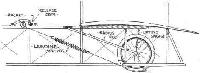
| Diagrammatic sketch illustrating the suspension of the Short biplane, and the method of mounting the "disappearing" wheels so that the machine will land on the skis if the driver releases the ratchet pawl device by which the spring tension is maintained.
|
 |
Журнал - Flight за 1910 г.
|
| Diagrammatic sketch illustrating the control of the elevator and the rudder on the Short biplane. The elevator planes flex from the front edge by the manipulation of a lever. The rudder pivots on a vertical column by the action of pedals. Both are normally held in their neutral position by elastic springs.
|
 |
Журнал - Flight за 1910 г.
|
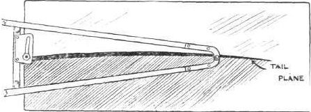
| Sketch illustrating the mounting of the horizontal tail plane on the Short biplane. The tail is fixed in flight, but its angle of incidence is adjustable within a small range by means of the slotted bracket illustrated above.
|
 |
Журнал - Flight за 1910 г.
|
|
|
 |
Журнал - Flight за 1910 г.
|
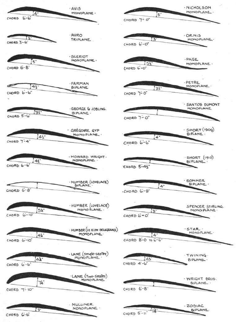
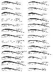
| WING SECTIONS. - The above diagrams afford an interesting comparison of the wing sections of aeroplanes exhibited at Olympia. They are all drawn to a common scale, but have been set at an arbitrary angle of incidence, which does not necessarily represent that of the aeroplane In actual flight.
|
 |
C.Barnes - Short Aircraft since 1900 /Putnam/
|
| Short No. 2 The drawing shows the original design before modification.
|
 |
C.Barnes - Short Aircraft since 1900 /Putnam/
|
| Short No.3
|
 |
P.Lewis - British Aircraft 1809-1914 /Putnam/
|
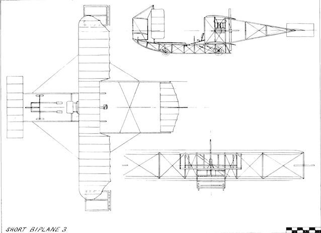
| Short Biplane 3
|
 |
Журнал - Flight за 1910 г.
|
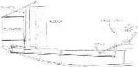
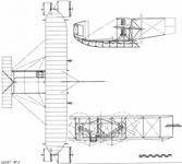
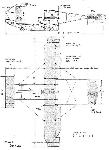
| THE NEW "SHORT" BIPLANE. - Elevation and plan.
|