M.Goodall, A.Tagg British Aircraft before the Great War (Schiffer)
Deleted by request of (c)Schiffer Publishing
LAMPLOUGH Orthopter & Lifterplane (Lamplough & Sons, Albany Works, Willesden Junction, London, NW)
This machine was designed to operate on the principles of bird flight and was exhibited incomplete at the Aero Show of March 1909 at Olympia.
It consisted of an elongated framework of ash members covered with Continental fabric and containing the mechanism for operating a pair of biplane wings, with their leading edges facing one another. The propulsion system consisted of two pusher propellers on long shafts driven from the forward part of the machine. A swaying motion was imparted to the lifters, by cranks, and their angle of incidence was controlled by links. Conventional biplane wings, with five pairs of interplane struts, were mounted to the sides of the framework, and biplane elevators with single rudders at front and rear.
Needless to say the Orthopter was a failure and in 1910 was followed by a biplane ornithopter with wings actuated by a 25hp motor, which was probably a modification of the earlier machine.
Data
Span 20ft
Area 945 sq ft
Weight 900 lb
P.Lewis British Aircraft 1809-1914 (Putnam)
Lamplough Orthopter
Designed and built by Lamplough and Son Ltd. at Albany Works, Willesden Junction, London, N.W.10, the Orthopter was exhibited at the Olympia Aero Show of 1909. Designed to operate on the principles of bird flight, the machine consisted of two pairs of biplane wings moving with a swaying motion in a figure-of-eight between a pair of similar fixed wings. Biplane elevators, complete with attendant rudders, were fitted fore and aft for control, forward motion being imparted to the ash structure by two pusher propellers. Span, 20 ft. Wing area, 945 sq. ft. Weight loaded, 950 lb. Price, ?1,000 with guarantee of flight.
Lamplough Lifterplane
The Lifterplane was built during 1910 by Lamplough and Son Ltd., of Albany Works, Willesden Junction, London, N.W. 10. It was a biplane ornithopter with wings actuated by a 25 h.p. engine, and is believed to have been the Orthopter modified.
Журнал Flight
Flight, March 27, 1909
FLYERS AT OLYMPIA.
Lamplough (LAMPLOUGH AND SON).
The flying machine which has been designed by Mr. Lamplough and constructed by his firm at Willesden is of an altogether unusual description, and quite unlike anything which has probably ever been built elsewhere. In order to appreciate its principle it is necessary to know what idea governed its design, and for that it is necessary to revert to Professor Pedigrew's theory of bird wing flight. Broadly speaking, that theory may be summed up by stating that the stroke of a bird's wing forms the figure eight, and Mr. Lamplough, accepting that view as suitable for a basis of mechanical flight, set himself the problem of reproducing it in an actual machine. The mechanical system he has devised consists in imparting a kind of swaying motion to two biplanes arranged longitudinally with their cutting edges facing one another. The planes are hinged, as also are the columns which support them, and as they sway to and fro a pair of cranks dip and tilt alternately, the adjacent edges, so that in a complete cycle an approximate figure of eight is performed. As the two biplanes approach one another the adjacent edges are tilted, and the planes being forced through the air create a lifting effect; when their motion is finished these edges are drawn downwards by the cranks, and as the biplanes recede it is their outer edges which are in turn relatively elevated so that once more a lifting effect is produced. The outer edges do not actually vary their position - it is only the inner edges which rise and fall - for it is along these edges that the planes are hinged to their supports. This part of the machine is a lifting device pure and simple, and forms the central portion of the structure; extended on either side, however, are a pair of biplanes proper with their cutting edges arranged transversely in the usual way. In front and behind are biplane elevators enclosing single rudders, and propulsion is effected by a pair of wooden propellers.
In the machine exhibited the whole construction is of wood, but when finished the vertical supports will be of tubular steel and the diagonal ties of steel wire. We understand that models which have been made have given remarkable results, lifting themselves by clockwork mechanism right up into the air, and a curious feature which has been found to be associated with this principle is that the lifting planes act as a parachute to steady the descent when the motive power stops. The lifting action, of the lifting planes which has already been described may perhaps be better understood by considering it as analogous to the slight paddling motion which a swimmer makes with his hands whilst he floats on his back.
 |
P.Lewis - British Aircraft 1809-1914 /Putnam/
|
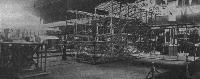
| Lamplough ornithopter appeared incomplete at the Olympia Aero Show in March 1909.
|
 |
Журнал - Flight за 1909 г.
|
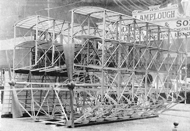
| AERO SHOW. - The Lamplough Orthopter Biplane, seen from behind. The central planes, which run longitudinally, sway to and fro with a lifting effect, while the lateral biplanes on either side are rigid in the usual way. At the extreme rear is a biplane elevator containing a rudder, and in front there is a precisely similar structure. The machine is unfinished.
|
 |
Журнал - Flight за 1910 г.
|
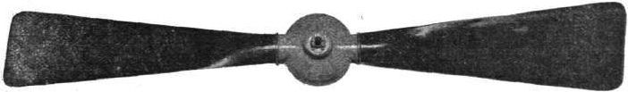
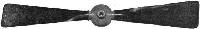
| In the Lamplough propeller the blades are each made from a single piece of wood, and are hollowed out from the root towards the tip. They are mounted in a hollow copper stamping which forms the boss.
|
 |
Журнал - Flight за 1909 г.
|
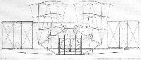
| AERO SHOW.- The Lamplough Orthopter Biplane, front elevation, showing the cranks which sway the lifters and the link motion which reverses their angle of inclination so that each stroke is effective. The dotted lines indicate the limiting positions of the lifters in each direction.
|
 |
Журнал - Flight за 1909 г.
|
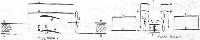
| The Lamplough machine has been designed to lift itself direct from the ground by the aid of waving aeroplanes. It has stationary aeroplanes for gliding.
|
 |
Журнал - Flight за 1909 г.
|
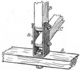
| Lamplough's flexible fastening.
|