В.Обухович, А.Никифоров Самолеты Первой Мировой войны
В процессе производства самолетов компания AGO постепенно отходила от концепции двухбалочных машин, и в 1916 г. был создан новый разведчик СIV - классический биплан, но довольно оригинальной конструкции. Самолет представлял собой в основном деревянный биплан с ферменным фюзеляжем. Рамы оперения, стойки и поперечный силовой набор фюзеляжа были выполнены из стальных труб. Мотор закрывался алюминиевыми капотами, носовая часть до задней кабины летчика-наблюдателя с трех сторон имела фанерную обшивку, нижняя грань - дюралевую, а от кабины наблюдателя до оперения - фанерную. Все остальные поверхности покрывались полотном. Крылья трапециевидной в плане формы с элеронами на обоих. Ферма крыла была выполнена одностоечной с дополнительной одинарной стойкой, что давало возможность стрелку увеличить сектор огня. На СIV устанавливался двигатель Бенц Bz.IV. Вооружение машины состояло из одного курсового пулемета "Шпандау" и турельного пулемета "Парабеллум".
Несмотря на серьезные недостатки (слишком большую массу и нестабильность в воздухе), СIV развивал достаточно высокую скорость и легко уходил от истребителей противника.
Кроме фирмы AGO, самолет производился по лицензии еще двумя компаниями. Всего было выпущено около 100 машин.
Технические данные AGO С IV
Двигатель 1 х Бенц Bz.IV (220 л. с.)
Размеры:
размах х длина 11,90 х 8,25 м
Площадь крыльев 37,5 м
Вес:
пустого 900 кг
взлетный 1350 кг
Максимальная скорость 190 км/ч
Потолок 5500 м
Продолжительность полета 4 ч
Вооружение:
пулеметное 1 синхронный пулемет,
1 подвижный пулемет
Экипаж 2 чел.
O.Thetford, P.Gray German Aircraft of the First World War (Putnam)
Ago C IV
The name Ago was first borne in 1911 by the products of Aeroplanbau G. Otto und Alberti. In 1912 Ago Flugzeugwerke G.m.b.H. was founded as a branch of the Otto Company in Munich (the name Ago being derived from the initials of Aerowerke Gustav Otto), and early in the First World War produced the twin-boom C I and C II types in small numbers. These were designed by the Swiss engineer A. Haefeli, who was earlier with the Farman concern and later returned to Switzerland.
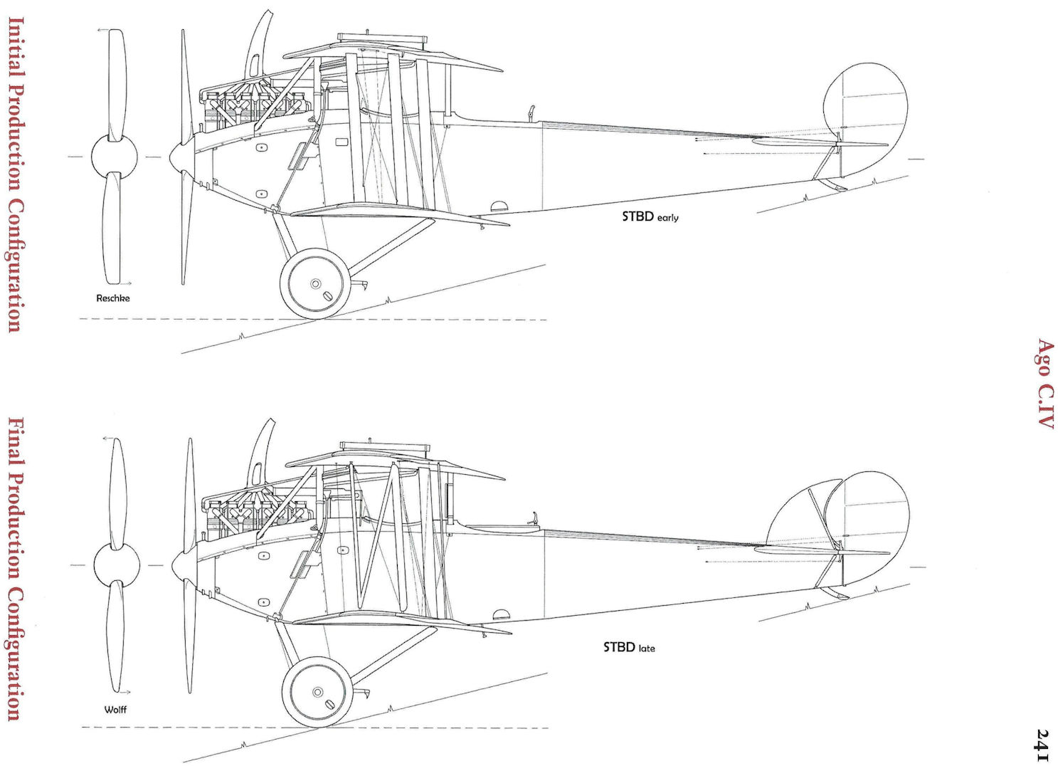
During 1916 Ago made an attempt to produce a high-performance two-seater, mainly for reconnaissance duties, with a good field of defensive fire. This eventually emerged in the shape of the C IV. Initially this machine appeared without a fixed vertical fin and with normal incidence bracing wires between the closely spaced outer interplane struts. In the production version a vertical fin was added to improve directional stability: it also eased the strain of piloting over long distances. At a later date the cable incidence bracing of the interplane struts was replaced by a rigid diagonal strut, resulting in an elongated "N" configuration of streamlined steel tube.
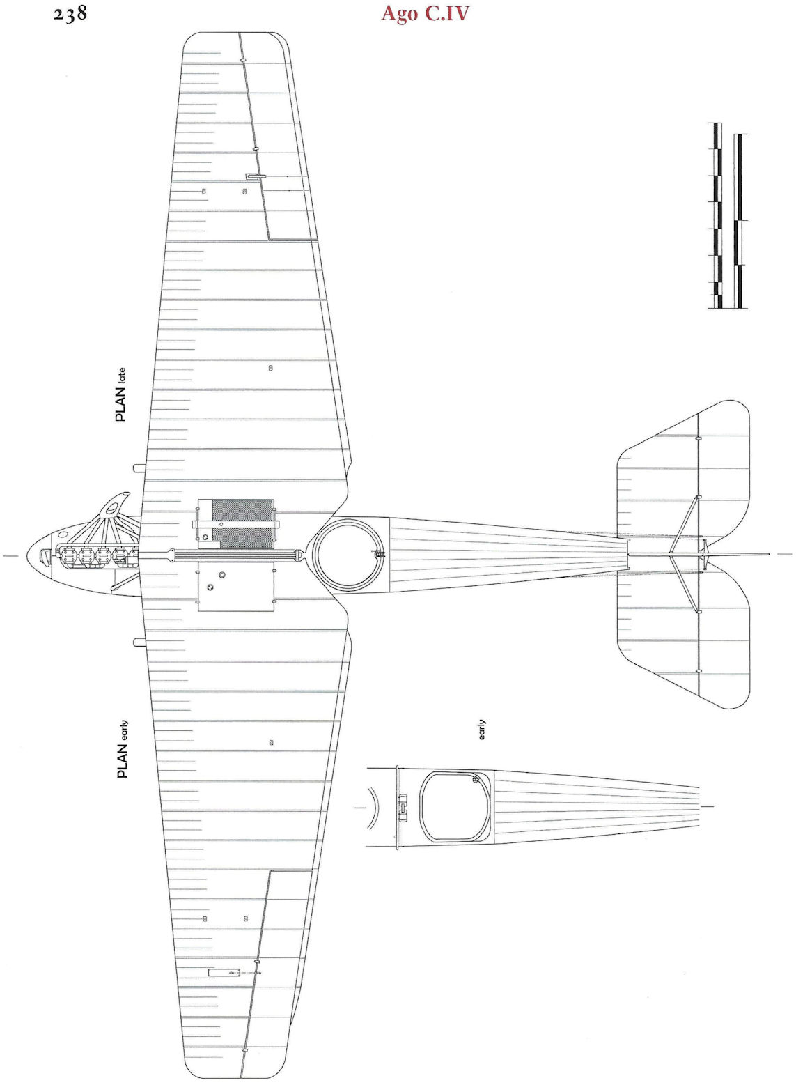
The most unusual feature of the Ago C IV was the tapering of the fabric covered wings which, as will be seen from the G.A. drawing, tapered quite sharply and uniformly from the maximum chord at the centre-section to the minimum chord at the square cut tip. Not only were the wings tapered but the two fabric-bound, main box-spars of Danzig pine also converged from root to tip. The ribs were of I-section, formed by a poplar web (fretted with the usual lightening holes) with ash capping strips, and not only was every rib in each panel a different size, but the distances on each rib where the spars intersected were different. As the wings also tapered in thickness from root to tip, further manufacturing complications were added, and it was undoubtedly this factor that precluded greater numbers of the aircraft being built. Although efficient, the Ago C IV took far too long to construct.
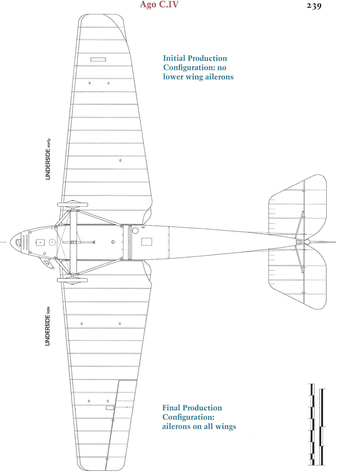
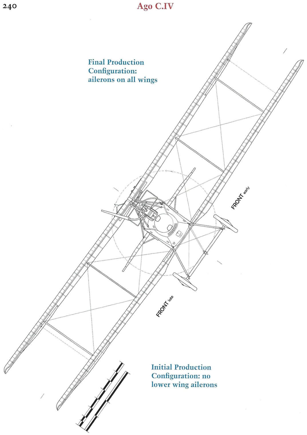
Other unique features of the wing structure were the closely spaced outer struts and the omission of the inner front interplane strut. This gave the observer an additional, limited, forward field of fire through the wings. It is of interest to note that on an Ago C IV captured by the Allies, a wire was fitted where this strut would normally have been and in the ensuing report in contemporary journals this can be mis-interpreted as a standard fitting. Flying and landing wires were also dispensed with at the forward spar locations. At the rear spar stations both sets of cables appeared in the outer bay: the inner bay was braced only by duplicated flying wires. This undoubtedly helped to minimise drag and consequently to improve performance. All four ailerons had a marked degree of washout and were linked with a streamlined steel strut. They were hinged to a false spar and actuated by a crank fixed to the upper ailerons which was operated by cables running through the lower wing, then over a pulley and up to the crank, adjacent to the interplane struts. On the earlier production machines ailerons were attached to the top wing only.
The radiator and gravity fuel tank were housed respectively in the root section of the starboard and port centre-sections and the piping ran through the centre-section struts, for added cleanliness of design. The main fuel tank was underneath the pilot's seat.
The fuselage structure was orthodox in design, but of unusual composite construction, with four wooden longerons (spruce aft of the rear cockpit and ash forward) and horizontal and vertical spacers of steel tube. With internal wire bracing aft of the cockpit section, and diagonal steel tube forward, a strong braced box-girder structure was formed. The curved top decking to the rear of the cockpits was a completely detachable, light framework which greatly facilitated access for servicing. A clean nose entry was achieved by the use of a spinner on the airscrew and the complimentary shaping of the metal panels around the nose and cylinder block of the 220 h.p. Benz engine. Also worthy of note was the complete enclosing of the forward-firing fixed Spandau gun. The remainder of the fuselage, which tapered to a vertical knife-edge, was ply-covered from the front undercarriage strut to the rear cockpit, aft of which it was fabric covered, except underneath, where it was ply-covered aft of the rear cockpit and aluminium covered forward of that point.
The tailplane had two box-spars, wooden ribs and split, unbalanced elevators, all of which were fabric covered. The balanced, comma-shaped rudder and fin were of light-gauge steel tubes and also fabric covered. Light steel struts braced the fin to the tailplane and the tailplane to the fuselage.
Streamlined steel tube vees formed the basis of the undercarriage chassis, with diagonal bracing between the front struts. The axle and spreader-bars were enclosed by a streamlined fairing, and a "claw" type brake was fixed to the middle of the axle.
The Ago C IV was active in small numbers during 1917. In February, Hans Schroder of Fl. Abt. 284A recorded that: "At last the new machines arrived. They were not Rumplers but Agos, with very pointed wings, and our first flights showed them to be most unstable in the air. Their climbing capacity was not very great and we were very disappointed with them."
Lt. Vater (an observer with Schroder's unit) had a remarkable escape during a photo reconnaissance on 18th February 1917 when his Ago was hit by A.A. fire at 3,000 m. over Thann (Vosges) and his pilot Sgt. Lulsdorf was killed. The machine fell in a series of wild inverted dives with Vater clinging upside down in the rear cockpit. The Ago eventually hit the ground inverted. Vater was dazed but heard infantrymen call to him and then assist him into a trench as the French began to shell the aircraft. Besides cuts and bruises he sustained a broken jaw, but was able to return to his Section within ten days.
About 70 Ago C IVs were in service in 1917-18 and not all the 260 aircraft ordered from sub-contractors were delivered.
TECHNICAL DATA
Purpose: Two-seat reconnaissance.
Manufacturers:
Ago Flugzeugwerke (Ago).
Flugzeugbau Schutte Lanz (250 aircraft) (Schul).
Waggonfabrik Joseph Rathgeber (10 aircraft) (Rat).
Power Plant: 220 h.p. Benz Bz IV 6 cylinder in-line water cooled.
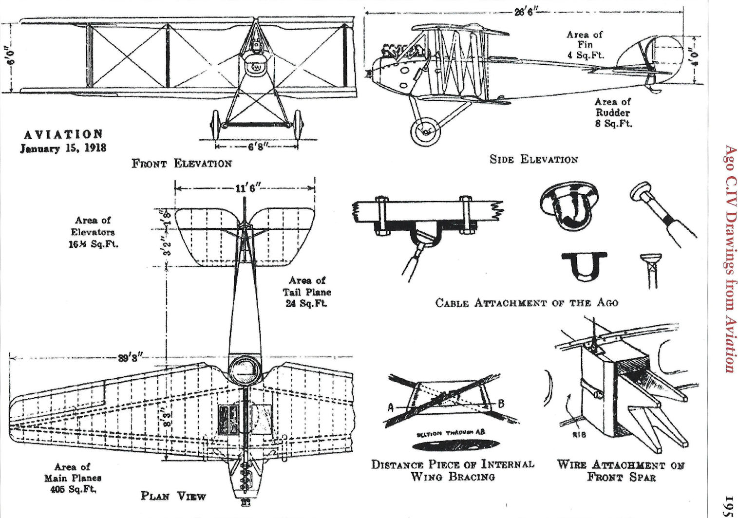
Dimensions: Span, 11.90 m. (39 ft. 0 1/2 in.). Length, 8.25 m. (26 ft. 4 3/4 in.). Height, 3.50 m. (11 ft. 5 3/4 in.). Wing area, 37.5 sq.m. (405 sq.ft.).
Weights: Empty, 900 kg. (1,980 lb.). Loaded, 1,350 kg. (2,970 lb.).
Performance: Maximum speed, 190 km.hr. (118.75 m.p.h.). Initial climb, 3,000 m. (9,840 ft.) in 22 min. Ceiling, 5,500 m. (18,040 ft.). Duration, 4 hr. (750 km. range).
Armament: One fixed Spandau machine-gun for pilot. One free-firing Parabellum machine-gun for observer.
J.Herris Otto, AGO and BFW Aircraft of WWI (A Centennial Perspective on Great War Airplanes 37)
Ago C.IV
Ago had exhausted the potential of the pusher configuration with its C.I, C.II, and C.III designs. To achieve better performance and to create a design that could be sold to the Prussian-dominated Fliegertruppe, Ago turned to the tractor configuration.
The result was the Ago C.IV, an innovative design of conventional construction that offered much better speed and climb than the pushers that preceded it.
The Ago C.IV was most easily distinguished from other two-seaters in having a sharply-tapered wing planform. Most WWI aircraft had untapered wings of rectangular planform for ease of manufacturer. However, the induced drag (drag induced by lift) depends on the wing planform, and theoretical calculations indicate that an elliptical wing planform minimizes induced drag. (See the Spitfire for an example of an actual design using this principle.) An elliptical planform wing is difficult to manufacture. However, it can be approximated by the tapered wing planform, which is a compromise.
The tapered wing has less drag than a rectangular wing but is harder to build. It has more drag than an elliptical wing but is easier to build.
The resulting C.IV with 220 hp Benz Bz.IV engine was faster than most two-seat reconnaissance airplanes. It was carefully designed to have clean lines and be relatively streamlined for the time. The combination of good power, uncluttered lines, and tapered wing planform gave it good speed and climb for its time. It was much faster than the C.I that Ago had been building, and had the tractor configuration preferred by the Fliegertruppe. Ago appeared to have found the formula, and the C.IV was ordered in quantity starting in June 1916.
Actual design of the Ago C.IV had started in late 1915. Another innovative feature of the C.IV was the lack of a forward, inboard bracing strut to provide a better field of fire forward between the wings for the observer. Ago was given Patent No. 299,149 for this innovation on Oct. 7, 1915, as they were designing the C.IV.
The Ago C.IV prototype flew in early 1916 and immediately demonstrated good performance. In trials flown on May 21 the prototype reached 4,000 m altitude in 32 minutes, fast for the time. This encouraged Idflieg to order 24 aircraft in June 1916. Contemporary Idflieg files referred to the Ago C.IV as the so-called light C-type. It was thus a precursor of the later CL-class.
Type-testing was completed in mid-June. The testing revealed the need to wing strengthening, and after two reinforcements of the metal wing fittings the required strength was achieved.
An order for 10 aircraft was given to the Munich-based Waggonfabrik Josef Rathgeber AG to bring that company into much-needed aircraft production. Initially the order was for the Rathgeber C.I but was later re-designated the Ago C.IV(Rat) when Idflieg rationalized aircraft designations. However, these aircraft were never delivered and the parts were reduced to spares.
Spare production capacity was available at Schutte-Lanz, best known for its airship manufacture as a competitor to Zeppelin. By this time airships were losing favor and the superior Zeppelins could fill requirements. None of Schutte-Lanz's own aircraft designs were selected for production and Idflieg ordered 250 Ago C.IV(Schul) aircraft from them to utilize their space production capacity. The size of the order indicated Idflieg’s interest in the C.IV.
In December 1916 the Ago C.IV arrived at the front. The pilots, who had been used to the stable and reliable Ago C.I were anticipating the C.IV to combine these qualities with significantly improved performance. However, they were soon disappointed. As soon as the C.IV went into service, a rash of fuselage failures occurred during landing. However, this problem was quickly corrected in January and deliveries continued.
As the crews logged increasing flight time on the C.IV, fatalities due to side-slipping increased alarmingly. The Ago C.IV was grounded at the end of April pending investigation and solution of the flight-control problem.
The original C.IV prototype and production aircraft had ailerons on the upper wing only and did not have a fixed fin. As a result of the accidents the flight controls of the C.IV were extensively redesigned to improve its flight characteristics. Ailerons were fitted to all wings and a fixed vertical fin was added to the tail. In addition, most all the aircraft delivered by Ago after serial 8950/16 and all built by Schutte-Lanz had an additional bracing strut between the outer wing struts. Idflieg also tested Ago C.IV 1521/17 fitted with conventional two-bay bracing. The first Schutte-Lanz built C.IV was type-tested May 7-8, 1917, during which the metal wing fittings failed again and had to be reinforced. Cleared for combat, few Schutte-Lanz built C.IVs reached the front.
The tapered wing planform gave good performance but contributed to the flight-control problem and the technology of the time was not adequate to 'tune' the wing's aerodynamics for good stability. With most rectangular planform wings, the designers 'washed out' the angle of incidence at the wingtips to ensure the wing stalled first at the wing root, countering its tendency to stall first at the tips where the ailerons were located, ensuring the pilot retained aileron control during stall recovery.
After the modified C.IV was returned to the front in the May-June timeframe, the C.IV was moderately successful but was unpopular with aircrews. Continuing pilots' resistance and flight-control problems caused Idflieg to ground the C.IV again on September 7, 1917 and cancel production.
The Ago C.IV was the last Ago design to be placed in production.
Ago C.IV Aircraft Production
Order Serials Qty Notes
June 1916 2740-2763/16 24 Ago
Sept. 1916 3714-3723/16 10 Rathgeber (not completed; reduced to spares)
Oct. 1916 5500-5749/16 250 Schutte-Lanz*
Nov. 1916 3600-3623/16 24 Ago
Nov. 1916 8950-8999/16 50 Ago
Feb.1917 1521-1570/17 50 Ago
May 1917 5575-5674/17 100 Ago. Few if any delivered. Order transferred to LVG C.II(Ago) trainers in Sept. 1917.
* Order reduced to 150 in July 1917 St cancelled in Oct. 1917 after 66 aircraft were delivered.
Ago C-Type Specifications
Ago C.III Ago C.IV
Engine 160 hp Mercedes D.III 200 hp Benz Bz.IV
Span, Upper 11.0m 11.90 m
Wing Area - 37.5 m2
Length 7.0 m 8.25 m
Height - 3.50 m
Empty Weight - 900 kg
Loaded Weight - 1,350 kg
Maximum Speed - 190 km/h
Climb to 3,000 m - 22 min.
Ceiling - 5,500 m.
Журнал Flight
Flight, December 13, 1917.
THE AGO - AN INTERESTING ENEMY AEROPLANE.
A MOVE in the right direction has undoubtedly been made by the Air Ministry, in collecting a number of enemy aeroplanes, aeroplane parts, and engines at a London depot, and to grant facilities to aeroplane designers and representatives of responsible firms to view this collection. The query might be raised why the collection has not been thrown open to the public, but the various exhibits are of such a nature that they appeal more particularly to the trained engineer than to the general public, arranged as they are to show every constructional detail of the different machines. For the purpose for which the collection is intended the machines and parts are most admirably arranged. Thus, in the case of complete machines, these are shown with one side stripped, up to the centre line of the fuselage. The other side is left uncovered. In this way it is possible to obtain on the one side an impression of the general arrangement of the machine, while, by merely walking over to the other side, one can inspect, at leisure, every spar, strut, wire and fitting, Great care and foresight has been shown, also, in the manner in which various parts, such as spars, &c, have been cut through in places, to allow of inspecting sections and internal construction. In this manner there are practically no component parts of which the general design and detail construction are not instantly clear from a very brief inspection. We do not propose to give, in this issue, a complete list of the exhibits, since, in any case, these change from time to time, but we hope later on to be able to publish sketches and descriptions of other machines.
For the present we will confine ourselves to dealing with one captured enemy aeroplane - the Ago - which, thanks to the courtesy of the Air Board officials, our representatives have had the opportunity of examining in detail.
The first impression one receives on being suddenly confronted with the captured Ago biplane is apt to be one in which surprise mingles with curiosity. As regards its general lines, the Ago is of a strikingly unusual appearance, mainly, no doubt, due to the fact that its wings are tapered very pronouncedly from root to tip. This is very unusual in any modern machine, and when it is suddenly met with in a German machine of comparatively recent date - from various marks on the machine one gathers the impression that it was built certainly no longer ago than the first months of this year - the question that first comes to mind is naturally enough related to the raison d'etre of this unusual design.
In the first place, it is obvious that whatever it was the designer was aiming at, he was prepared to go to considerable trouble to obtain it, since the construction of such tapered wings as those of this Ago are not by any means an attractive proposition commercially, entailing, as it does, the separate construction of half the ribs, no two of which are alike from root to tip in one wing. Also, as the spars converge to a point at the tip, they intersect the ribs at varying distances from root to tip, which again means extra work in manufacture. As for the spars themselves, they also taper from root to tip, again more trouble and expense.
What, then, are the reasons which have led a designer to sacrifice so much from a manufacturing point of view, in order to obtain his end? A walk round the machine soon furnishes the reply to the question. When standing in front of the machine one is at once struck by the peculiar bracing of the front spar. Instead of the usual interplane strut there is on the Ago only a single solid wire running from the front lower spar to the front top spar, while no lift or landing cables of any sort are employed between the two front spars.
This feature, then, will probably be found to contain the solution of the peculiar design. By doing away with the front bracing, a much freer field of firing is obtained; and there can be little doubt that this was the object for which the designer was striving.
Owing to the backward slope of the leading edge of the planes, the outer inter-plane struts are farther back than they would be in a machine with straight wings, and also owing to the taper, closer together and therefore obstructing the field to a smaller extent. The narrower chord near the tip will result in a smaller travel of the centre of pressure, hence possibly the twist on the wings may become less, and the absence of front bracing be a less serious defect than one is inclined to imagine at first.
When we say absence of front bracing, this is not quite correct, since, as already indicated, a single solid wire runs from top to bottom front spar. As is well known, in biplanes, with top and bottom planes of the same area, and with the conventional spacing of gap about equal to chord, the top plane carries about 30 per cent, more load than the bottom one, or roughly, 4/7 and 3/7 respectively. By running a wire from the top to the bottom front spar, the latter is therefore made to carry a certain share of the top spar's load, thus relieving, to a certain extent, the enormous bending moment that must be present on a comparatively heavily loaded machine, whose front spars have a distance of some 13 ft. 6 in. between supports.
So much for the general design of the Ago. As regards the construction there is much detail work that is interesting and unusual. The fuselage, which is, as in the majority of German aeroplanes, of very, roomy proportions, as regards occupants' accommodation, is covered with fabric except the front around the engine, which is covered in with three-ply. The floor of the fuselage is of three-ply from the stern to the gunner's (rear) cockpit. From there to the nose the floor is three-ply, covered with aluminium. In section, the fuselage is rectangular, a light and comparatively flat structure forming a turtle back over the top of the main fuselage framework. This turtle back is built up as a separate unit, and is easily detachable by means of a neat and very simple clip. In case of severe stresses being put on the fuselage, it is therefore an easy matter to detach the top covering and examine and adjust the internal bracing.
The four longerons, which are of square section, are pine, from the rear cockpit to the stern, while in front they are made of ash. The struts are in the form of steel tubes, and the solid wire bracing is attached to the struts in the manner shown in one of the accompanying sketches. A small socket, apparently machined out of the solid steel bar, has holes drilled in its edges, through which the bracing wires pass. This socket is slipped over the end of the tube, which has small dents in its end to give more room for the loop of the wire, and the socket, with its strut, is secured to the longeron by a bolt passing through it, with the nut and a spring washer inside the socket, as shown in section in one of our sketches. Except for the fact that the longerons are pierced by two holes - the horizontal and vertical fuselage struts are staggered in relation to one another - close to one another, this arrangement appears to be very neat, and certainly takes up very little space.
In front, the fuselage bracing is in the form of diagonal steel tubes, no wires being employed. The rear cockpit is occupied by the machine gunner, who 'is seated on a small seat built up of a framework of steel tubing, over which is stretched canvas. This seat is so hinged and sprung that immediately the gunner stands up the seat springs into a vertical position out of his way in case he wishes to do his shooting in a standing position. When horizontal, the seat is supported by a slanting steel tube, pivoted at its lower end to the floor, and having its upper end running in a steel guide, bolted to the under side of the seat. The principle will be better understood by reference to one of the accompanying sketches. The gun is mounted on a swiveling bracket, which, in turn, is supported on a rotatable gun ring of wood, forming, in effect, a turntable, by means of which the gun may be traversed in any desired direction. To prevent damaging the nose of the machine and the propeller, a stop is provided for the gun in the form of two small frames clipped to the rear legs of the cabane, which prevents the gun barrel from travelling too far inboard.
The pilot's seat, which is in the front cockpit, is placed on top of the main petrol tank resting on the floor of the fuselage. A service petrol tank is carried in and mounted flush with the top plane just to the left of the cabane. In the corresponding opening in the upper right hand wing, is carried the radiator, and in connection with these two it is interesting to note that the water and petrol is led through the right and left cabane legs respectively, thus saving a certain amount of piping, which would otherwise be exposed to the air.
The controls are, more or less, of the usual German type, with a vertical lever terminating at the top in a double handled grip, and mounted - via a universal joint - on a longitudinal rocking shaft, having at its other (rear) end crank levers for the attachment of the aileron cables. On the machine in question, no guns were mounted, but from the various fittings it appeared that there were at one time two machine guns mounted above the engine, and with the usual interrupting gear for clearing the propeller blades.
The large engine - a 230 h.p. Benz - is mounted on two longitudinal bearers, which are in turn supported from the fuselage by three direct supports - at the rear a sloping panel of ply-wood, in the middle by tubes sloping up from the junction of the rear panel to the lower longerons, and at the front by another panel of ply-wood, this a vertical one. In addition to these direct supports, the engine mounting is further braced by tubes to the upper longerons, and by diagonal tubes from top to bottom longerons. It has already been mentioned that the main petrol tank is placed on the floor of the pilot's cockpit, while the petrol service tank is mounted in an opening in the top plane. The oil tank, which is comparatively small, is carried under the engine housing on the right-hand side of the crank chamber. The propeller, which was not in place on the machine inspected, probably had a "spinner," or hemispherical nosepiece over the boss, as this would appear to go well with the nose of the fuselage, which is of rounded section at this point.
The main planes are, as already indicated, tapered from root to tip to a very marked extent, the trailing edge sloping considerably more than the leading edge. Successive ribs are of different depth, as well as chord, owing to the fact that the spars, in addition to their convergence, are of varying depth from root to tip. Whether, however, the ribs change progressively in such a manner that all are of actually the same section, but reduced geometrically, or whether they alter in shape as well as in size has not yet been ascertained, but judging from the way in which the spars taper it would appear that the end ribs are not of quite the same section as the inner ones.
Constructionally, the ribs are of the usual I section, with webs which appear to be made of poplar, and with flanges of ash. In between the spars the webs are lightened by cutting out in the usual way. The leading edge is of pine of U, or, more correctly speaking, of a rounded V section between ribs, but left solid where the ribs are attached to it. The trailing edge is a thin lath about 1 in. wide by about 3/16 in. thick.
The main wing spars are of an interesting construction, and their section is shown in the accompanying sketches. The two flanges are glued to thin webs (about 5 mm.), the whole being wrapped in fabric. No tacks or screws are employed for securing the webs to the flanges, the glueing and wrapping being apparently relied upon to be sufficient for the purpose. At the points where occur the ribs a three-ply distance piece is glued into the hollow spar, but so narrow is this that in several places we noticed the tacks through the rib flanges had penetrated the spar flange, missed the three-ply distance piece, and had its end projecting inside the hollow of the spar. The rear spar, which was of slightly smaller dimensions than the front spar, was different in that its upper flange had been spindled out, otherwise the two spars were similar, also in that in both the top flange was not quite so thin as the bottom flange. The spars were constructed of what appeared to be some kind of pine, possibly Dantzig.
Where the bolt, serving as an anchorage for the wire running to the top plane occurred, the spar was strengthened by a packing piece of peculiar form. This is shown in some of our sketches, which will, we hope, help to explain it. It will be seen that the saw cuts in the ends of this distance piece, leaves four tapering ends, which would have the effect of cantilever beams proportioned to carry an end load, the latter being considered as the lateral load on the spar at this point. Whether this, however, was in the designer's mind is doubtful. It is more probable that the shape of the piece is the result of an attempt at stiffening the spar for a considerable distance on each side of the joint, without carrying too much weight. The vertical bolt, to which reference was made above, is not passed through the spar itself, but through an additional stiffening piece glued to the front face of the spar. Two horizontal bolts through the spar, securing on the rear face of the spar the compression strut for the internal wing bracing, are the only attachment, apart from the glue, of this vertical packing piece to the spar proper. It is to be imagined that a pull on the inter-plane wire must result in a tendency to twist the spar, placed, as it is, so far from the vertical neutral axis of the spar. Altogether this joint impresses one as being very poorly designed indeed, in fact, it has the appearance of not having been designed at all.
The outer inter-plane struts are stream-line steel tubes, with a diagonal tube welded to them in the manner shown in the illustrations. In addition to this diagonal tube there is a wire running diagonally in the opposite direction, probably to ensure that the welded joints of the struts shall not have to work in tension under the changes in load, caused by the travel of the centre of pressure.
The ailerons, which have their tips at a slightly smaller angle of incidence than that of the inner ends, are hinged to a false spar slightly to the rear of the rear main spar. The section of this false spar is shown in one of our sketches. The leading edge of the aileron is in the form of a steel tube, partly enclosing which - and at some distance from it - is a strip of three-ply wood, the object of which evidently is to provide the requisite depth of the leading edge of the aileron without going to the extra weight of a tube of sufficient diameter. The method of attaching the ribs to this tube is also indicated in the sketches. A short strip of steel, quite thin, is bent around the tube, its two ends projecting back, and being accommodated in a slot in the rib. This strip is then soldered - and probably pinned, although this could not be ascertained - to the tubular leading edge.
Half-way between consecutive ribs, in order to help it retain its shape, small distance pieces are tacked to the three-ply, having their free ends abutting on the surface of the tube. Another sketch shows the tube to which the inter-aileron strut is attached. The crank lever of the upper aileron is a somewhat weird and complicated affair, having a forward projection curving up over the false spar, and dipping down in an opening between two ribs. To this projection is attached one of the aileron control cables, which runs over a pulley in the lower spar and internally in the lower wing to the cranks on the longitudinal rocking shaft. In plan view the aileron crank lever is bent and runs through a rib, the clip attaching it to the inter-aileron strut being similar to that of the lower aileron shown in the sketch. From this aileron crank, a cable passes over another pulley in the same casing as that of the first, and hence through the lower plane to the controls. It will thus be seen that both elevating and depressing the aileron is a positive movement.
The tubular leading edge of the ailerons is supported by a small bearing at the inner end, and by two clips of steel bent over the tube and bolted to the false spar at certain intervals. Thus each aileron is carried in three bearings. The outer end of the leading edge of the aileron is free. A fact which at once impresses itself on one in looking at the lateral control of the Ago is that the point from which the aileron is actuated is very near its inner end, leaving a very large amount of the aileron area outside, a fact which must give rise to considerable twisting stresses.
The tail planes are of similar construction as that of the main planes, the same form of box spars being employed. The stabilising plane is brought to the same level as the top of the fuselage, by dropping the lower longerons, somewhat after the fashion of the old Deperdussin monoplanes. A clip secures the front spar of the tail plane to the longerons, while the rear spar is attached by means of a sliding clip arrangement, which allows (not during flight) of adjusting the angle of incidence of the tail. The vertical fin, which is of tubular construction, is mounted on and moves with the tail plane. No very great amount of adjustment is therefore possible, as a comparatively small movement of the rear spar of the tail plane brings the rudder against the edge of the cut out portion of the fin. (See illustration.) The rudder, which is also built of steel tubes, has no support above the stern of the body, this being difficult to obtain in conjunction with the adjustable fin. The result is that the rudder is very much overhung and does not look any too strong for its work.
The under carriage is of the Vee type, built of steel tubes streamlined with wooden fairings. The axle is slung, by means of rubber band, from the apex of the Vee, and is enclosed in a streamline casing of aluminium. The lower half of this casing is bolted to the transverse tube of the chassis, while the upper half is hinged along this transverse tube and is allowed to move its trailing edge up and down according to the travel of the axle. A stout wooden tail skid sprung by means of rubber chord inside the fuselage, has, at its outer end, a metal protector in the form of a hemispherical bowl bolted to the end of the skid.
 |
J.Herris - Otto, AGO and BFW Aircraft of WWI /Centennial Perspective/ (37)
|
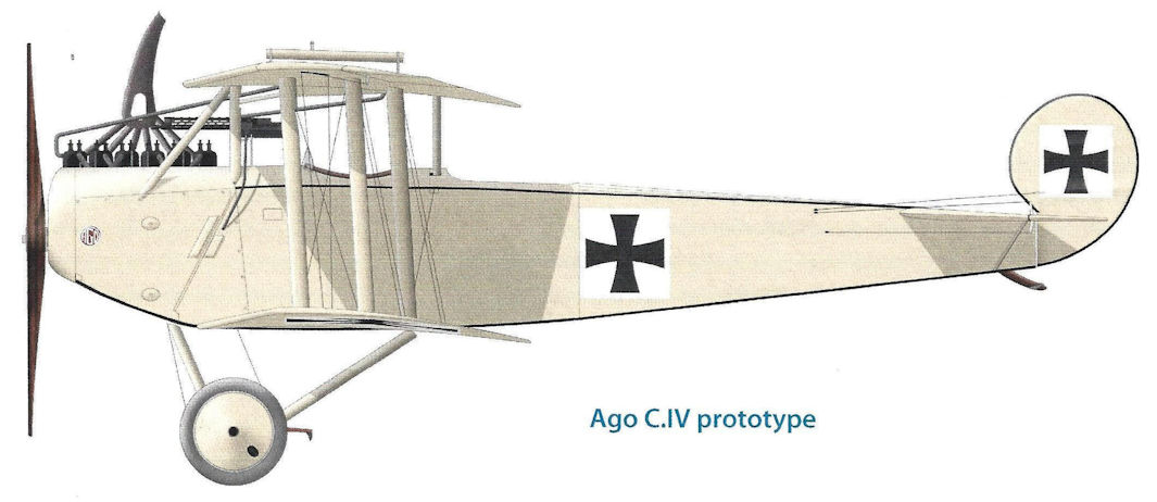
| Ago C.IV prototype
|
 |
J.Herris - Otto, AGO and BFW Aircraft of WWI /Centennial Perspective/ (37)
|
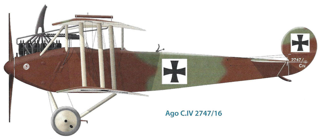
| Ago C.IV 2747/16
|
 |
J.Herris - Otto, AGO and BFW Aircraft of WWI /Centennial Perspective/ (37)
|
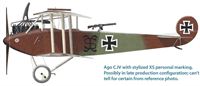
| Ago C.IV with stylized XS personal marking. Possibly in late production configuration; can't tell for certain from reference photo.
|
 |
J.Herris - Otto, AGO and BFW Aircraft of WWI /Centennial Perspective/ (37)
|
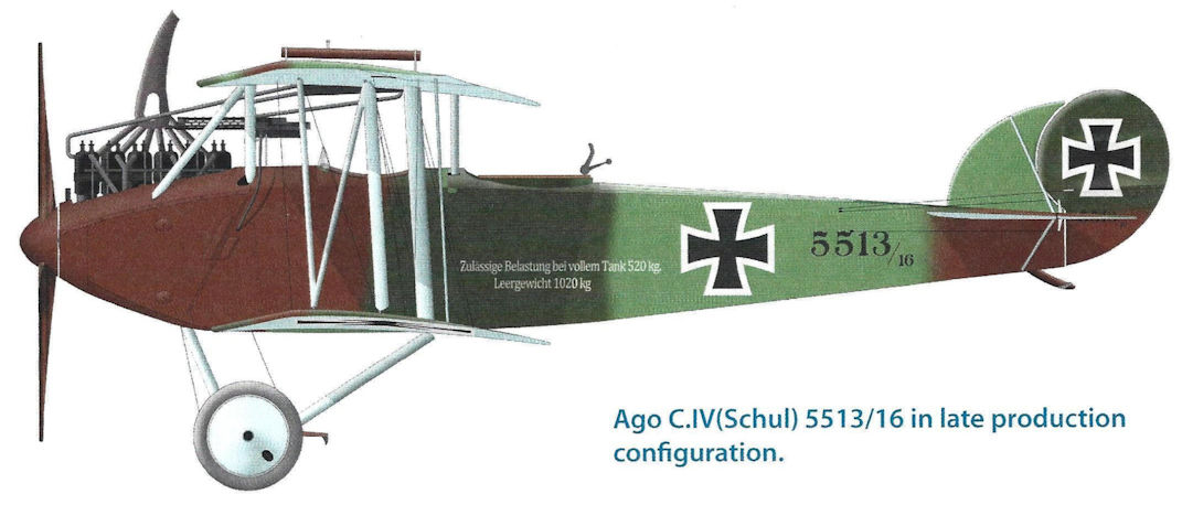
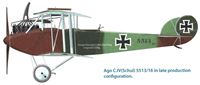
| Ago C.IV(Schul) 5513/16 in late production configuration.
|
 |
В.Обухович, А.Никифоров - Самолеты Первой Мировой войны
|
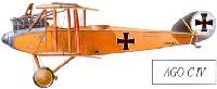
| AGO C IV
|
 |
J.Herris - Otto, AGO and BFW Aircraft of WWI /Centennial Perspective/ (37)
|
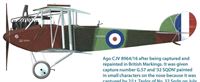
| Ago C.IV 8964/16 after being captured and repainted in British Markings. It was given capture number G.57 and '32 SQDN' painted in small characters on the nose because it was captured by 2/Lt. Taylor of No. 32 Sqdn on July 29, 1917.
|
 |
J.Herris - Otto, AGO and BFW Aircraft of WWI /Centennial Perspective/ (37)
|
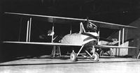
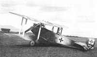
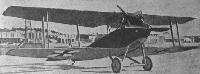
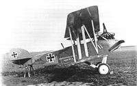
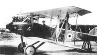
| The prototype Ago C.IV photographed at the Ago factory at Johannisthal in spring 1916. It was finished in an overall light color, not camouflaged. The nose contours and lack of propeller spinner also differentiated it from production aircraft. Other than that was similar to the initial production configuration except for being unarmed. There is no fixed fin, ailerons are fitted on the upper wing only. The forward inboard interplane struts normally seen on two-bay aircraft were omitted to enable the observer a larger field of fire forward; however, the rectangular wire in front of the observer's cockpit to prevent the observer firing into the propeller arc that was fitted to production aircraft was not fitted to the prototype. Although of conventional wood, wire, and fabric construction, the Ago C.IV had a number of innovative features and had a significantly better performance the Ago's earlier pusher designs. (Peter M. Grosz Collection/STDB)
|
 |
J.Herris - Otto, AGO and BFW Aircraft of WWI /Centennial Perspective/ (37)
|
|
|
 |
J.Herris - Otto, AGO and BFW Aircraft of WWI /Centennial Perspective/ (37)
|
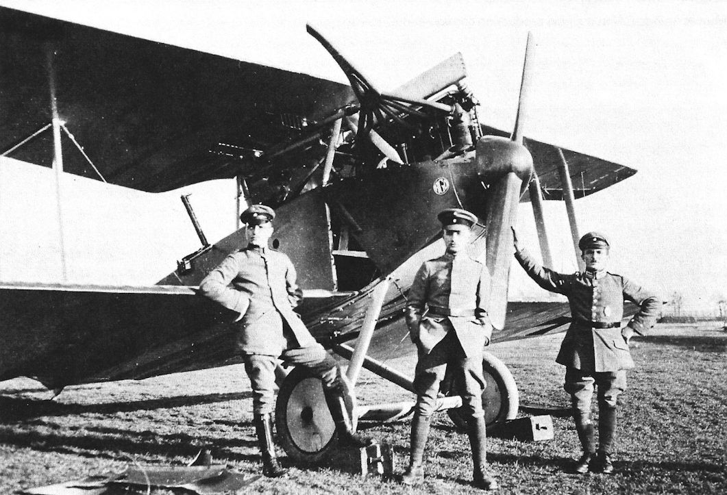
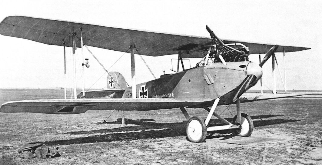
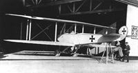
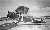
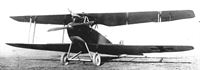
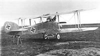
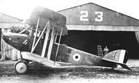
| The first production version of the Ago C.IV during type-testing at Adlershof in June 1916. Like the prototype, there is no fixed fin and ailerons are fitted on the upper wing only. Furthermore, it has a propeller spinner and revised nose contours.The forward inboard interplane struts normally seen on two-bay aircraft were omitted to enable the observer a larger field of fire forward. The broad interplane struts were painted in the undersurface color, likely light blue. However, unlike the light-doped prototype, this aircraft had the production two-tone camouflage scheme. The scheme was not very distinct and was green and red/brown.The Ago C.IV had a number of innovative features, some of which had to be modified after operational service, and had a significantly better performance the Ago's earlier pusher designs. (Peter M. Grosz Collection/STDB)
|
 |
J.Herris - Otto, AGO and BFW Aircraft of WWI /Centennial Perspective/ (37)
|
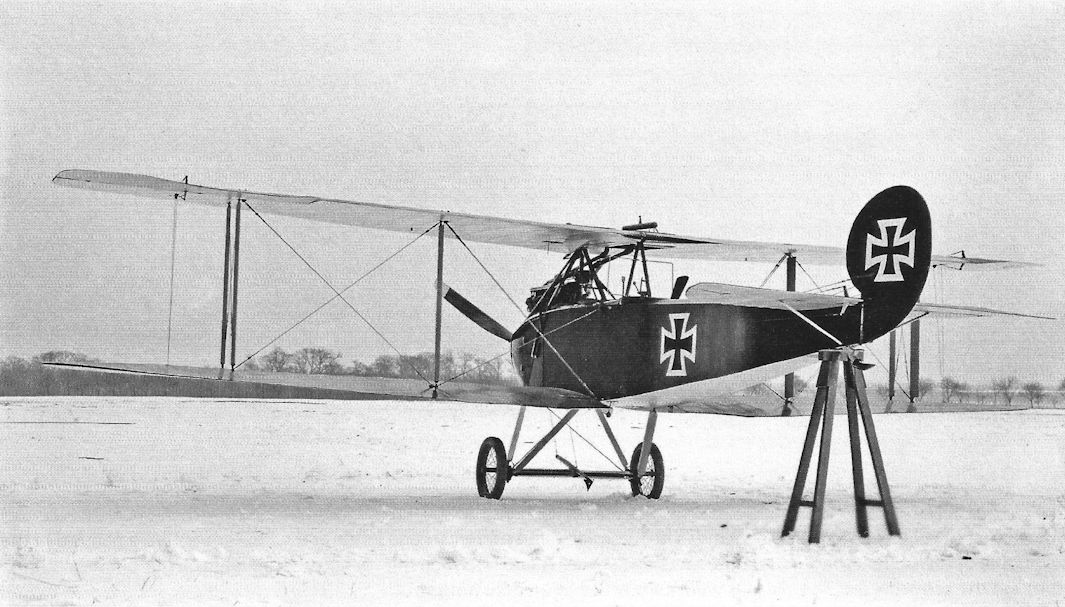
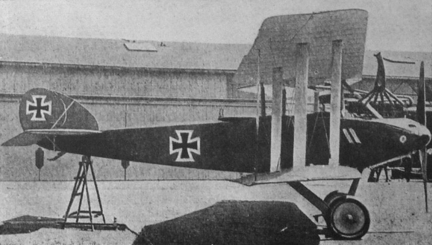
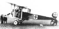
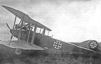
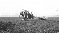
| Whereas the Ago C I to C III had all been twin-boom fuselage designs, their C IV was of fairly conventional layout, the only novelty the pronounced degree of taper on the one-and-a-half bay wings. Generally well regarded by its crews, the C IV used a 220hp Benz Bz IV, giving it a top level speed of 119mph at 4,000 feet; normal range was 497 miles. Production bottlenecks, attributed to wing assembly, limited deliveries to around 70 operational examples. This is an early example, with balanced rudder and no fixed fin.
|
 |
J.Herris - Otto, AGO and BFW Aircraft of WWI /Centennial Perspective/ (37)
|
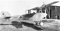
| Ago C.IV 2747/16 is an early machine in the initial production configuration from the first production batch. Camouflaged in a two color scheme, there is no fixed fin, ailerons are fitted on the upper wing only, and the broad interplane struts are painted the underside colors. The forward inboard interplane struts are omitted to enable the observer a larger field of fire forward and the rectangular wire in front of the observer's cockpit is to prevent the observer firing into the propeller arc. The fixed machine gun for the pilot is mounted over the engine. (Bruno Schmaling)
|
 |
J.Herris - Otto, AGO and BFW Aircraft of WWI /Centennial Perspective/ (37)
|
| This is early production C.IV 2764/16 photographed at Johannisthal; Ago logos appeared on the nose and center of the rudder cross on both sides. The insignia are painted on white squares; the rudder was not painted completely white but used a white square background for the insignia. (Peter M. Grosz Collection/STDB)
|
 |
J.Herris - Otto, AGO and BFW Aircraft of WWI /Centennial Perspective/ (37)
|
| Ago C.IV 3615/16 of the second production batch. The rectangular guard wire to prevent the observer from firing through the propeller arc is clearly shown. The aircraft is in initial production configuration (Peter M. Grosz Collection/STDB)
|
 |
J.Herris - Otto, AGO and BFW Aircraft of WWI /Centennial Perspective/ (37)
|
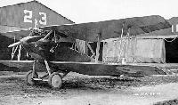
Schutte-Lanz-built Ago C.IV(Schul) prototype 5500/16 in February or March 1917. Although this prototype was in the initial configuration, all Schutte-Lanz-built Ago C.IV production aircraft had four ailerons and a fixed fin. (Peter M. Grosz Collection/STDB)
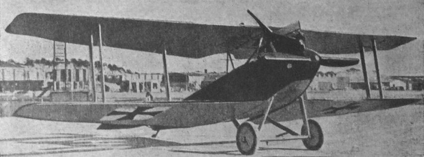
Age C IV, with 180 h.p. Argus As III. Note mounting of Spandau machine-gun to fire over cylinder heads.
|
 |
J.Herris - Otto, AGO and BFW Aircraft of WWI /Centennial Perspective/ (37)
|
| Schutte-Lanz-built Ago C.IV(Schul) prototype 5500/16 in February or March 1917. Although this prototype was in the initial configuration, all Schutte-Lanz-built Ago C.IV production aircraft had four ailerons and a fixed fin. (Peter M. Grosz Collection/STDB)
|
 |
J.Herris - Otto, AGO and BFW Aircraft of WWI /Centennial Perspective/ (37)
|
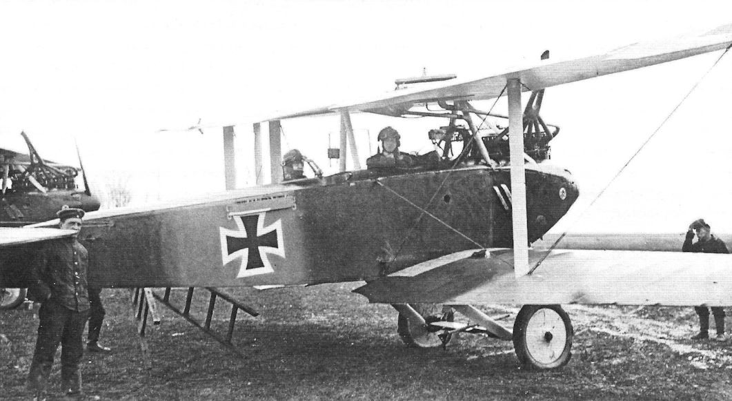
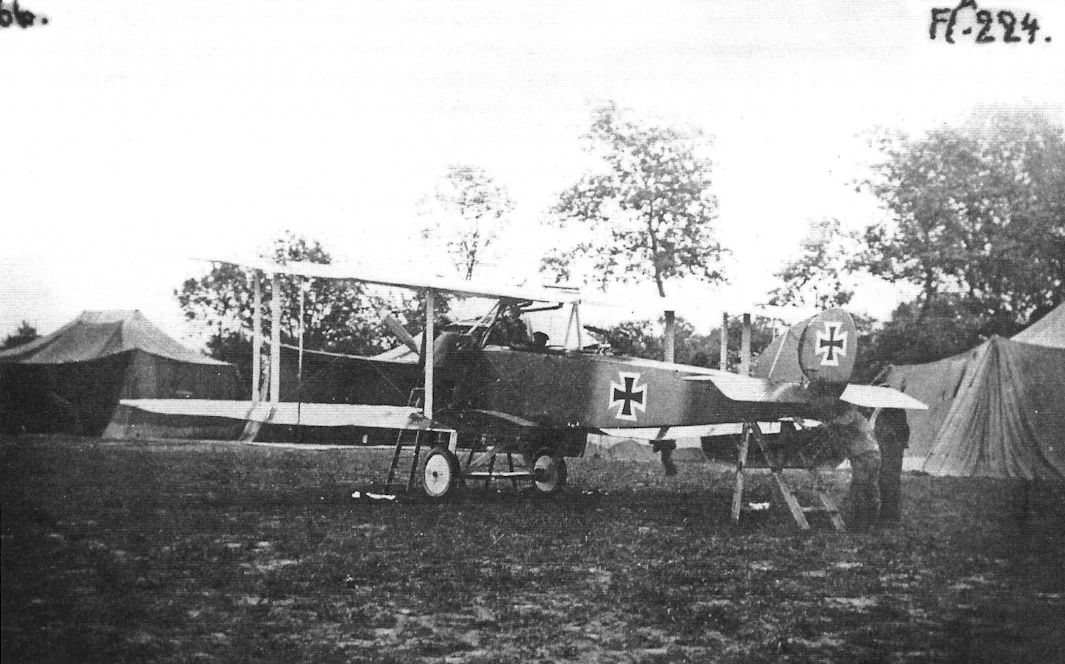
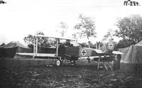
| Ago C.IV in initial production configuration attached to Flieger-Abteilung 14 on April 2,1917, at the Western Front airfield near Colmer. The observer was Oblt. Wunschman from 13 RIR and the pilot was Lt. Oppert.
|
 |
J.Herris - Otto, AGO and BFW Aircraft of WWI /Centennial Perspective/ (37)
|
| Ago C.IV at the front. (Bruno Schmaling)
|
 |
Jane's All The World Aircraft 1919 /Jane's/
|
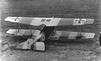
| Three-quarter Front View of an AGO C.IV armed reconnaissance Biplane of 1917. Note the tapered wing and the single strut between the outer pair and the fuselage
|
 |
J.Herris - Otto, AGO and BFW Aircraft of WWI /Centennial Perspective/ (37)
|
| Early-production Ago C.IV in initial production configuration. (Peter M. Grosz Collection/STDB)
|
 |
J.Herris - Otto, AGO and BFW Aircraft of WWI /Centennial Perspective/ (37)
|
| An Ago C.IV photographed with its crew. The Ago logo is on the nose. Perhaps the bad reputation of the Ago C.IV accounts for the crew's stoic expressions.
|
 |
J.Herris - Otto, AGO and BFW Aircraft of WWI /Centennial Perspective/ (37)
|
| Early-production Ago C.IV in initial production configuration.The rudder insignia are on white square backgrounds.
|
 |
J.Herris - Otto, AGO and BFW Aircraft of WWI /Centennial Perspective/ (37)
|
| Ago C.IV(Schul) 55xx/16 (likely 5504/16) from Flieger-Abteilung 47. It was in the final production configuration common to Schutte-Lanz-built aircraft - fixed fin, ailerons on all wings connected by an actuating strut, and the diagonal strut adding additional strength to the outer interplane strut bracing. (Bruno Schmaling)
|
 |
J.Herris - Otto, AGO and BFW Aircraft of WWI /Centennial Perspective/ (37)
|
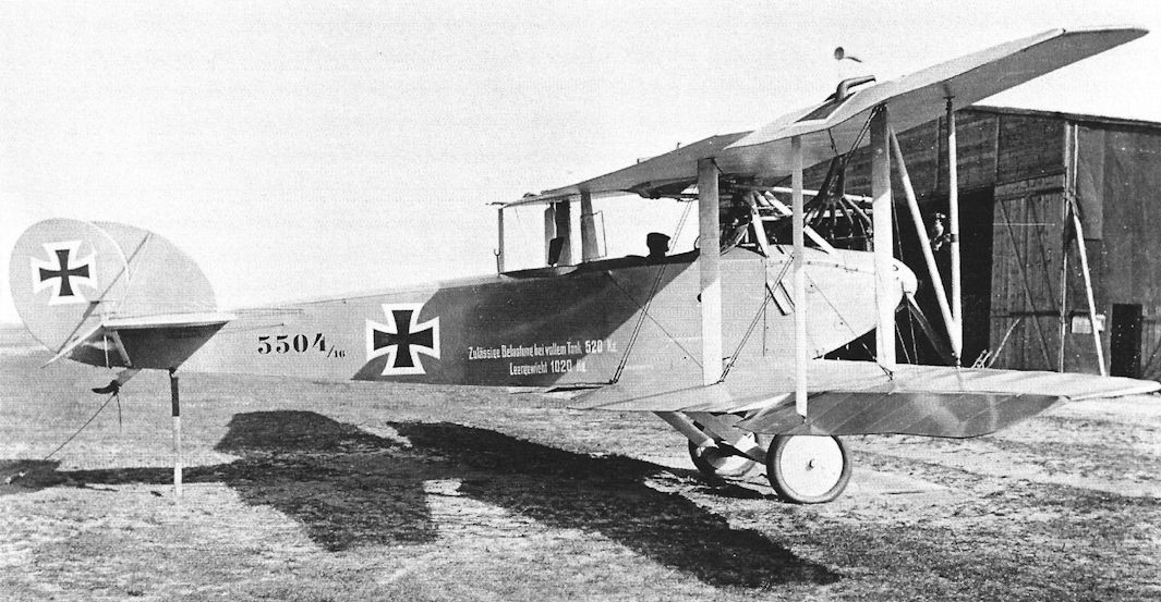
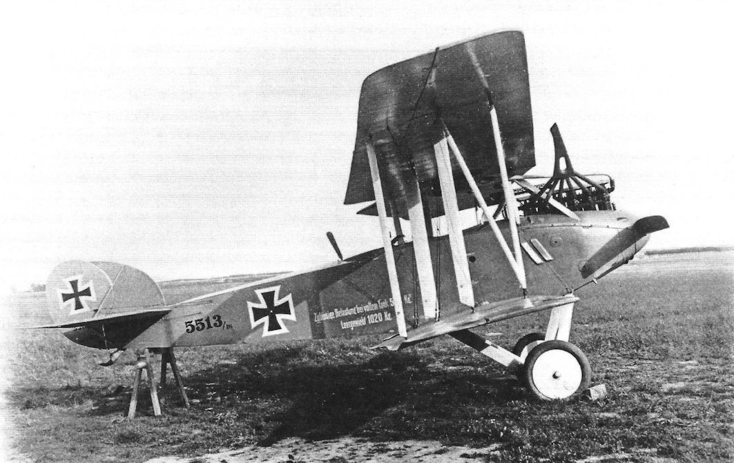
| Ago C.IV(Schul) 5504/16.The aircraft is in final production configuration including fixed fin, ailerons on all wings connected by an actuating strut, and a diagonal bracing strut added to the outer interplane strut assembly. However, it was not camouflaged.The fuselage text reads: Zulassige Belastung beivollem Tank 520 kg. (Permissable load at full tank 520 kg) Leergewicht 1020kg. (empty weight 1020 kg). (Peter M. Grosz Collection/STDB)
|
 |
J.Herris - Otto, AGO and BFW Aircraft of WWI /Centennial Perspective/ (37)
|
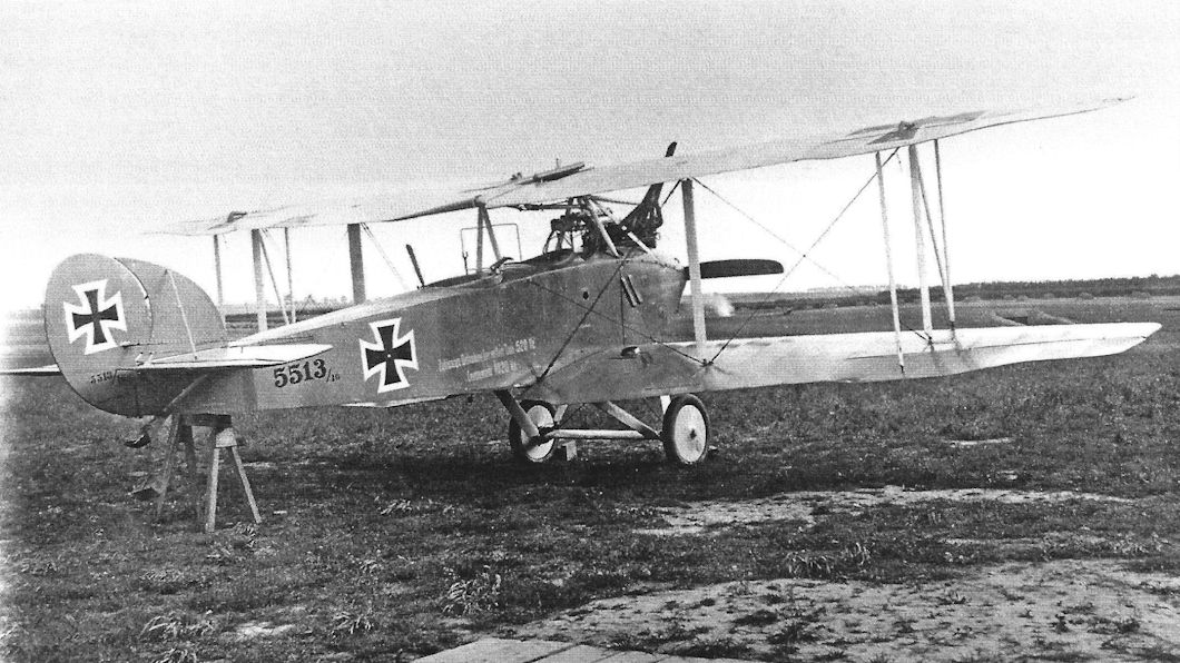
| Ago C.IV(Schul) 5513/16.The aircraft is in final production configuration including fixed fin, ailerons on all wings connected by an actuating strut, and a diagonal bracing strut added to the outer interplane strut assembly. The fuselage text reads: Zulassige Belastung beivollem Tank 520 kg. (Permissable load at full tank 520 kg) Leergewicht 1020 kg. (empty weight 1020 kg).This may indicate training use. (Peter M. Grosz Collection/STDB)
|
 |
J.Herris - Otto, AGO and BFW Aircraft of WWI /Centennial Perspective/ (37)
|
|
|
 |
J.Herris - Otto, AGO and BFW Aircraft of WWI /Centennial Perspective/ (37)
|
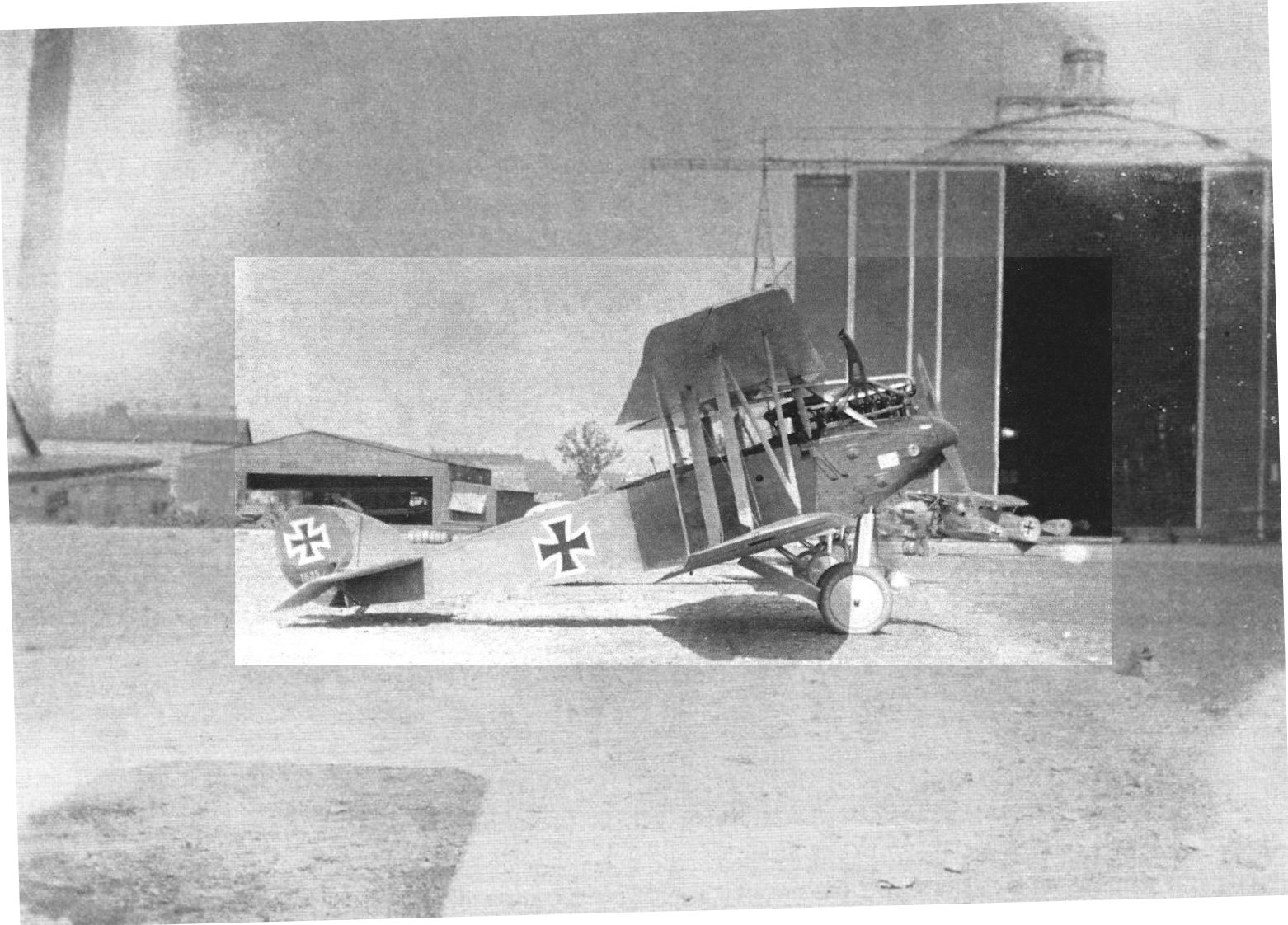
| Ago C.IV 8979/16 aircraft in the late production configuration in the field, although there are no diagonal bracing struts between the outboard interplane struts. The Ago logo is visible on the engine cowling.
|
 |
J.Herris - Otto, AGO and BFW Aircraft of WWI /Centennial Perspective/ (37)
|
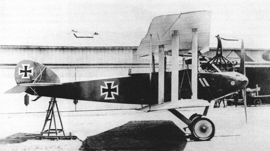
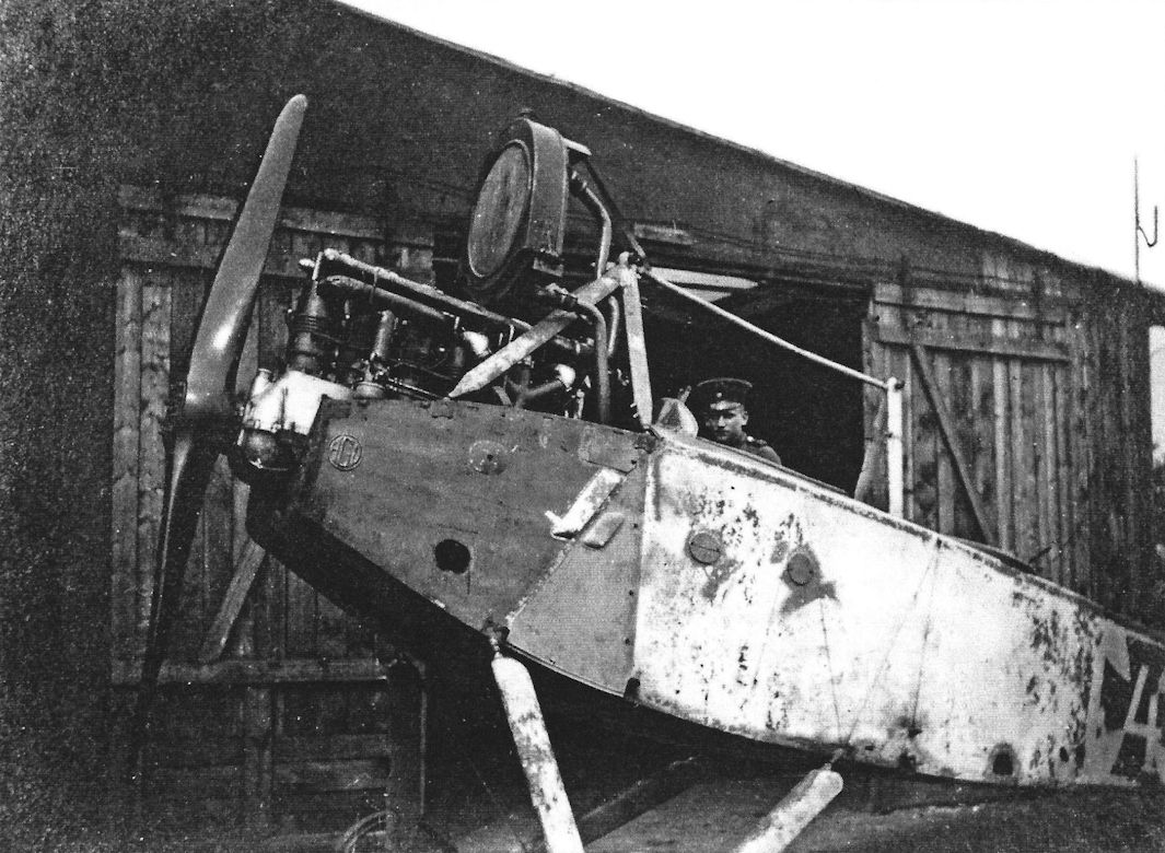
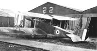
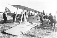
| Ago C.IV 1535/17 is in the final production configuration. The Ago logo on the nose indicates it was built by Ago. The aircraft is parked next to an airship hangar in the background. The pilot's fixed gun is visible.
|
 |
J.Herris - Otto, AGO and BFW Aircraft of WWI /Centennial Perspective/ (37)
|
Schutte-Lanz-built Ago C.IV(Schul). The interplane and undercarriage struts and wheel covers were painted in the light blue of the undersurfaces. Note the rectangular wire guard between the cockpits to prevent the gunner from firing through the propeller arc. The ailerons were connected by an actuating strut.
The Ago C.IV's forward inner interplane strut was omitted to give the gunner a better field of fire forward between the wings, and unlike most airplanes of the time the wings were tapered. Power was the 200 hp Benz Bz.IV engine.
|
 |
J.Herris - Otto, AGO and BFW Aircraft of WWI /Centennial Perspective/ (37)
|
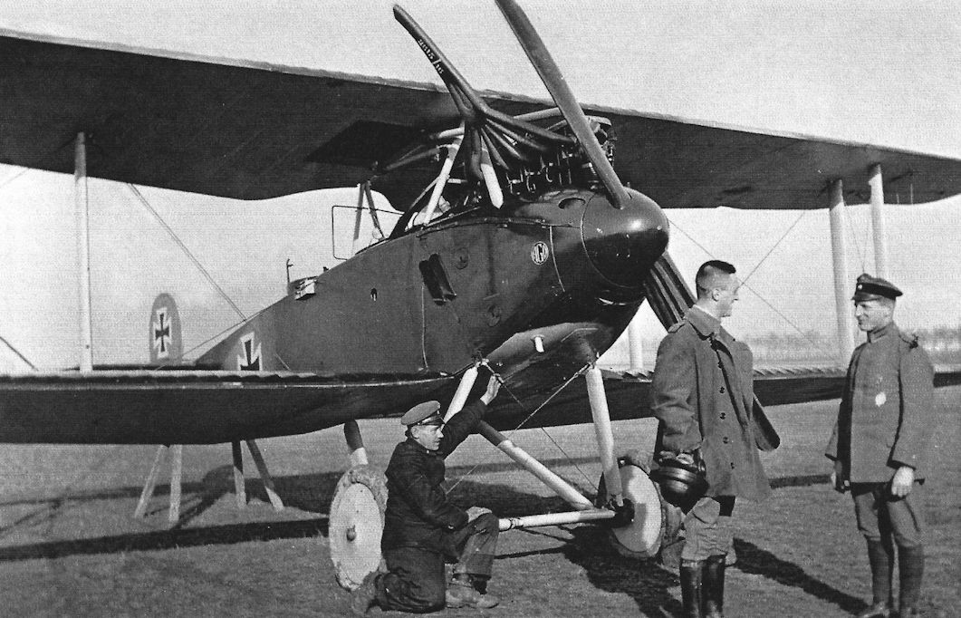
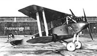
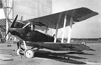
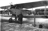
| Idflieg test pilot Wendeler poses with the modified version of the Ago C.IV during testing at Adlershof in the spring of 1917. In addition to fitting a fixed fin and ailerons on all wings, a diagonal strut was introduced between the outer pair of interplane struts for additional strength. (Peter M. Grosz Collection/STDB)
|
 |
J.Herris - Otto, AGO and BFW Aircraft of WWI /Centennial Perspective/ (37)
|
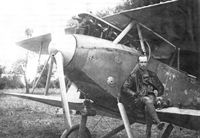
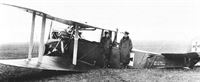
| View of an Ago C.IV and its pilot, Vzfw. Schweikowski from FAA 230, shows the relaxed pilot after the flight. The Ago logo is displayed prominently on the nose.
|
 |
J.Herris - Otto, AGO and BFW Aircraft of WWI /Centennial Perspective/ (37)
|
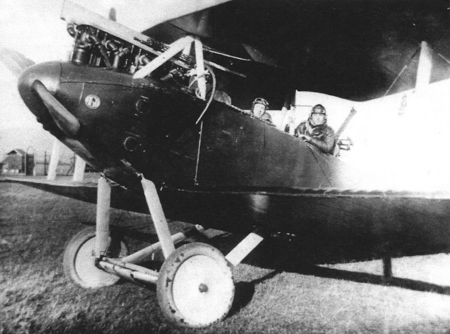
| View of an Ago C.IV and its pilot, Vzfw. Schweikowski from FAA 230, before the flight
|
 |
J.Herris - Otto, AGO and BFW Aircraft of WWI /Centennial Perspective/ (37)
|
| Ago C.IV aircraft with Ago logo on the nose and clearly visible pilot's fixed Spandau LMG 08/15 mounted above the engine.
|
 |
J.Herris - Otto, AGO and BFW Aircraft of WWI /Centennial Perspective/ (37)
|
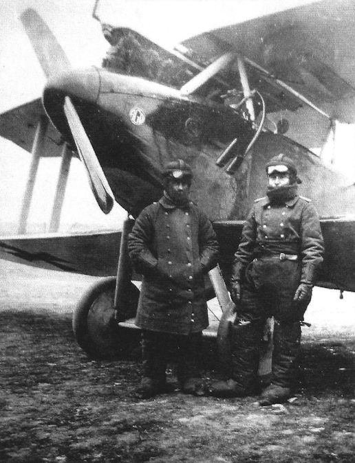
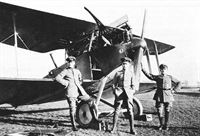
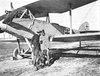
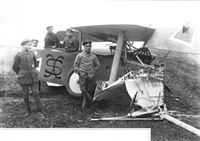
| Another late-production Ago C.IV from Flieger-Abteilung 47 with its aircrew. The Ago logo on the nose indicates it was built by Ago. (Bruno Schmaling)
|
 |
J.Herris - Otto, AGO and BFW Aircraft of WWI /Centennial Perspective/ (37)
|
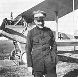
| An Ago C.IV(Schul) from Flieger-Abteilung 47. Despite the bad reputation of the Ago C.IV by this time the crewman seems in good spirits. (Bruno Schmaling)
|
 |
J.Herris - Otto, AGO and BFW Aircraft of WWI /Centennial Perspective/ (37)
|
| An Ago C.IV in the final production configuration.
|
 |
J.Herris - Otto, AGO and BFW Aircraft of WWI /Centennial Perspective/ (37)
|
| Ago C.IV aircraft of final production configuration in the field.
|
 |
Jane's All The World Aircraft 1919 /Jane's/
|
| ANOTHER VIEW OF THE AGO BIPLANE. - A slight difference in the strutting is noticeable in this view. The machine previously described in "FLIGHT" had a diagonal (incidence) strut between the two outer interplane struts. In the machine shown in this photograph this strut, it will be seen, has been replaced by a wire, thus conforming more with standard practice.
|
 |
J.Herris - Otto, AGO and BFW Aircraft of WWI /Centennial Perspective/ (37)
|
| Ago C.IV in final production configuration ready to take off on its next mission. (Peter M. Grosz Collection/STDB)
|
 |
J.Herris - Otto, AGO and BFW Aircraft of WWI /Centennial Perspective/ (37)
|
| Schutte-Lanz-built Ago C.IV(Schul) 5555/16 with the upper wing center section and lower inboard wings covered with transparent Cellon to give the crew and improved field of view.
|
 |
J.Herris - Otto, AGO and BFW Aircraft of WWI /Centennial Perspective/ (37)
|
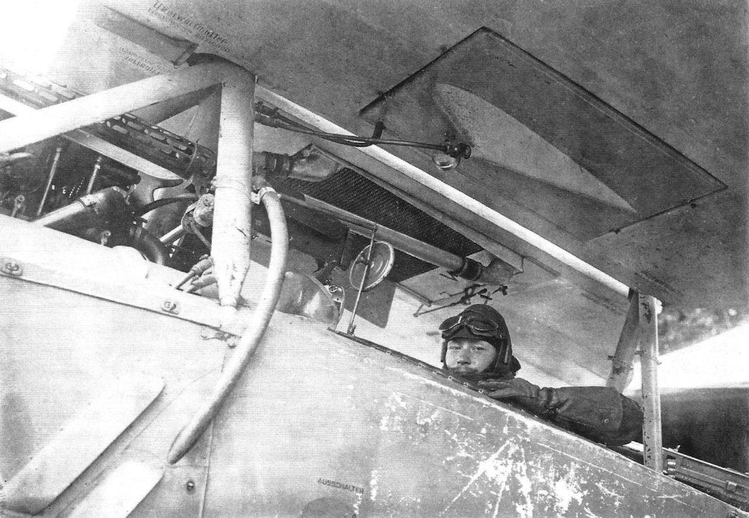
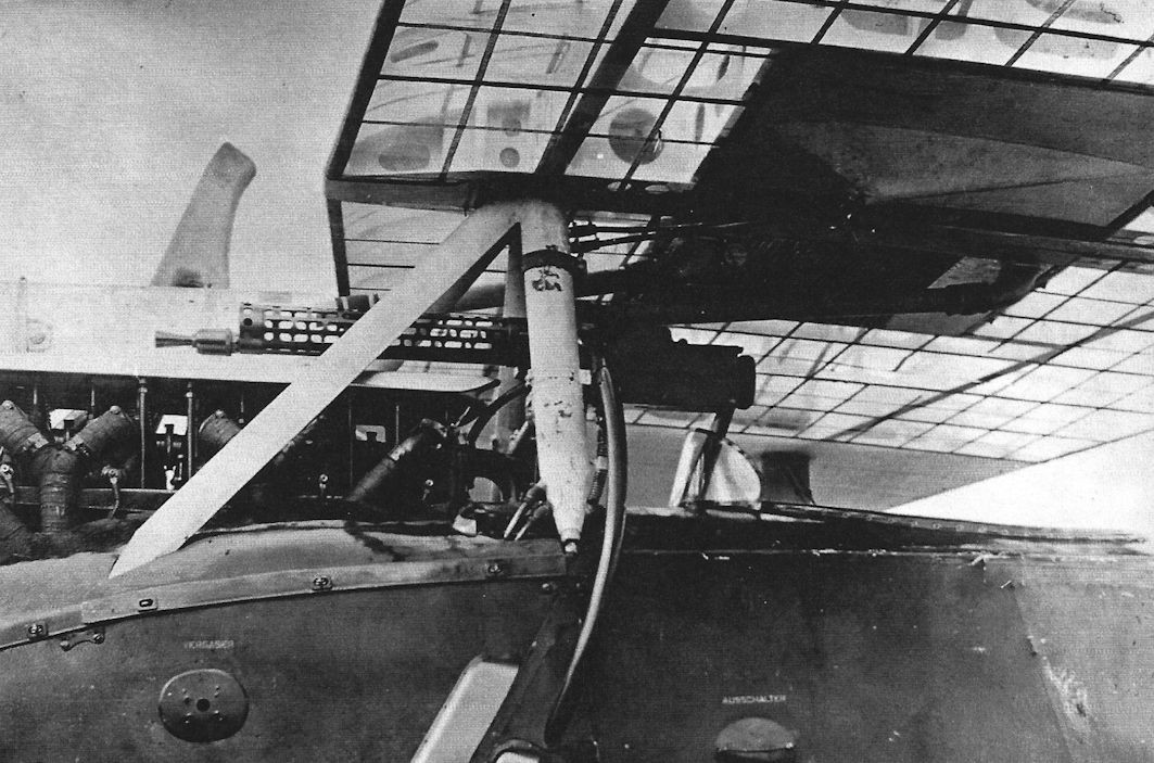
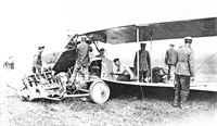
| Schutte-Lanz-built Ago C.IV(Schul) aircraft with the upper wing partially covered with transparent Cellon to provide the pilot with an improved view upward also shows the internal wing structure. The fixed pilot's machinegun is shown clearly; it was in a position unique to the Ago C.IV. (Peter M. Grosz Collection/STDB)
|
 |
J.Herris - Otto, AGO and BFW Aircraft of WWI /Centennial Perspective/ (37)
|
| Ago C.IV with a non-standard radiator undergoing testing. (Peter M. Grosz Collection/STDB)
|
 |
J.Herris - Otto, AGO and BFW Aircraft of WWI /Centennial Perspective/ (37)
|
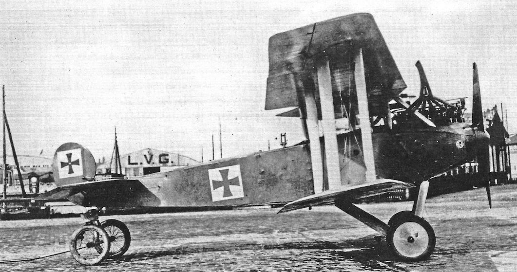
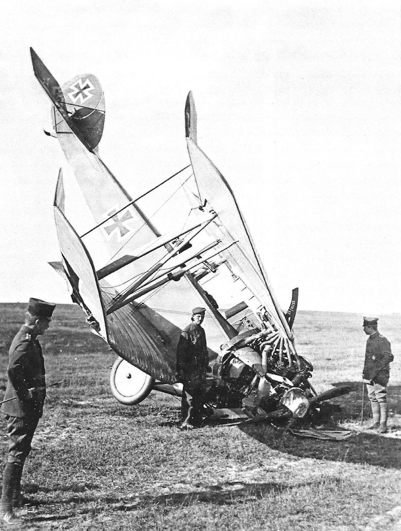
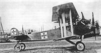
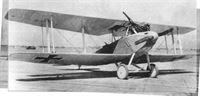
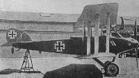
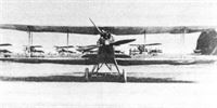
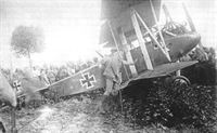
Captured Ago C.IV 8964/16 (works number 179), powered by Benz Bz.IV #30014. In the final production configuration, it was brought down near Woesten by 2/ Lt.Taylor of No. 32 Squadron on 29 July 1917. After the British markings were added "32 SQDN" was stenciled in white on the nose and fuselage. It had a Wolff propeller. The components of the wings were dated 15 February 1917. It was taken to the UK and later crashed. It was the only Ago C.IV captured by the British and was given a 'G' number (captured aircraft number) G.57.
This example of a late production Ago C IV was clearly considered something of a trophy by its No 32 Squadron, RFC, captors. This machine, C8964/16, captured on 29 July 1917, was flown to Britain for detailed evaluation, but crashed on 17 August 1917. Note Ago's adoption of a Sopwith style fixed fin on the later C IVs.
|
 |
J.Herris - Otto, AGO and BFW Aircraft of WWI /Centennial Perspective/ (37)
|
| Captured Ago C.IV 8964/16 after being assigned the captured aircraft designation G.57 and painted with British markings over the original German national insignia. It was the only Ago C.IV captured by the British and was painted in two-color camouflage of green and red/brown. Under test the engine must have produced 226 hp as noted on the upper photograph; nominal power was 220 hp.
|
 |
J.Herris - Otto, AGO and BFW Aircraft of WWI /Centennial Perspective/ (37)
|
|
|
 |
Форум - Breguet's Aircraft Challenge /WWW/
|
| Трофейный AGO С IV с британскими кокардами на крыльях
|
 |
J.Herris - Otto, AGO and BFW Aircraft of WWI /Centennial Perspective/ (37)
|
|
|
 |
J.Herris - Otto, AGO and BFW Aircraft of WWI /Centennial Perspective/ (37)
|
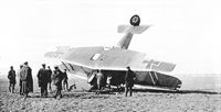
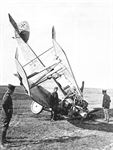
| An early production Ago C.IV on its nose. The two-color camouflage scheme is evident but not very distinct. It was in the initial production configuration - no fixed fin, ailerons on the upper wing only, and the forward inboard interplane struts normally seen on two-bay aircraft were omitted. The camouflage extended to the rudder. The airfoil radiator is offset to the right and the gravity tank is on the left. (Bruno Schmaling)
|
 |
J.Herris - Otto, AGO and BFW Aircraft of WWI /Centennial Perspective/ (37)
|
| Ago C.IV on its nose. (Reinhard Zankl)
|
 |
J.Herris - Otto, AGO and BFW Aircraft of WWI /Centennial Perspective/ (37)
|
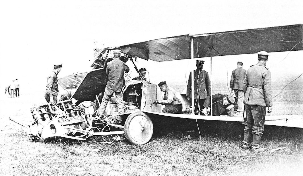
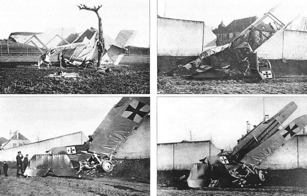
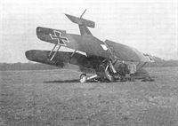
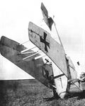
| Early production Ago C.IV aircraft after landing accidents. The fragile fuselage failed after landing.
|
 |
J.Herris - Otto, AGO and BFW Aircraft of WWI /Centennial Perspective/ (37)
|
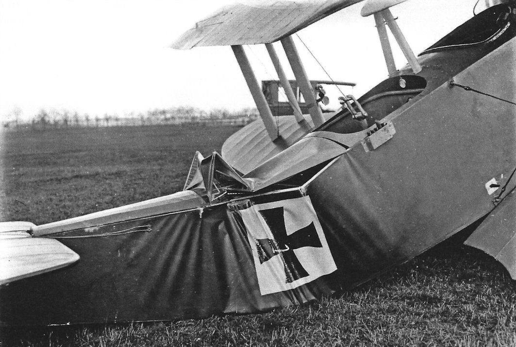
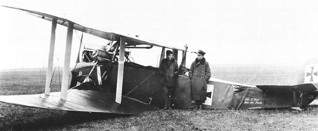
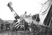
| Early production Ago C.IV aircraft after landing accidents. The poor flying qualities contributed to the landing accident. The aircraft below was flown by Lt. Auer and Obltn. Paulin, who had previously flown an Ago C.I. (Peter M. Grosz Collection/STDB)
|
 |
J.Herris - Otto, AGO and BFW Aircraft of WWI /Centennial Perspective/ (37)
|
| Early-production Ago C.IV of FAA 296 in initial production configuration.The aircraft has experienced a too-typical landing accident. (Bruno Schmaling)
|
 |
J.Herris - Otto, AGO and BFW Aircraft of WWI /Centennial Perspective/ (37)
|
| Below: Ago C.IV(Schul) 5519/16 after an accident.The aircraft is in final production configuration (Peter M. Grosz Collection/STDB)
|
 |
J.Herris - Otto, AGO and BFW Aircraft of WWI /Centennial Perspective/ (37)
|
| Ago C.IV on its nose.The aircraft is in final production configuration including fixed fin, ailerons on all wings connected by an actuating strut, and a diagonal bracing strut added to the outer interplane strut assembly. The fact it was not camouflaged and in final configuration may indicate it was built by Schutte-Lanz. (Peter M. Grosz Collection/STDB)
|
 |
J.Herris - Otto, AGO and BFW Aircraft of WWI /Centennial Perspective/ (37)
|
| Ago C.IV 8963/16 crashed on take-off on June 26, 1917 while being flown by Lt. Kruger of FA 26, who was unhurt. This was not uncommon of the Ago C.IV during rough field operations. Albatros C.XII(BFW) 1816/17 in the tent has unusual vents in its nose. (Peter M. Grosz Collection/STDB)
|
 |
J.Herris - Otto, AGO and BFW Aircraft of WWI /Centennial Perspective/ (37)
|
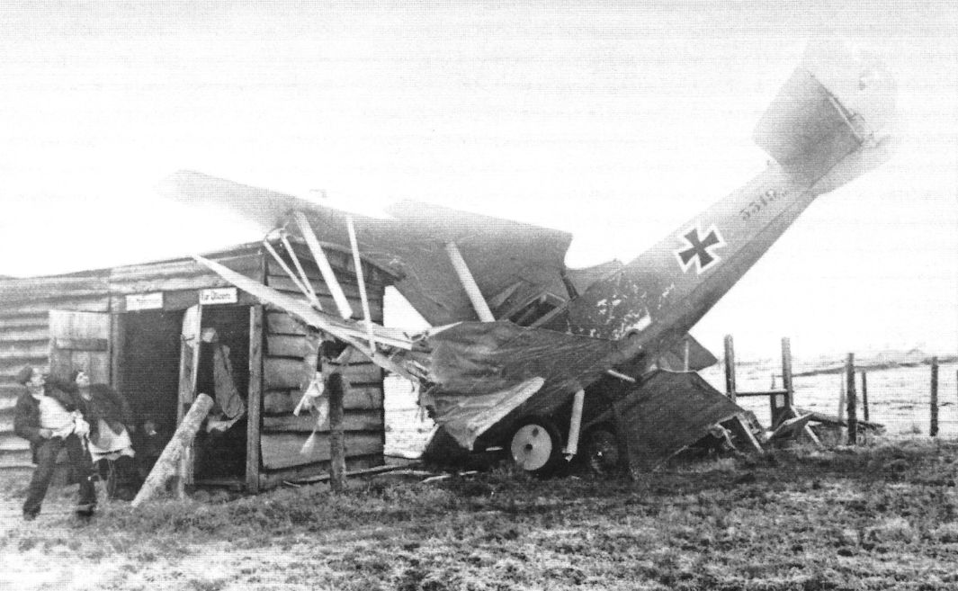
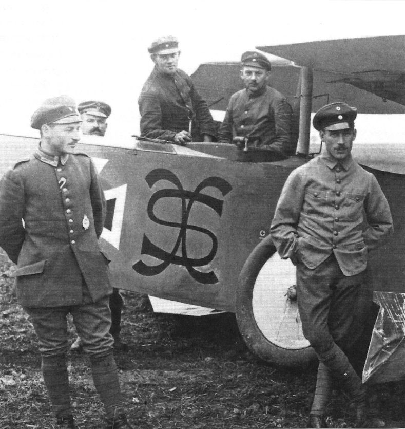
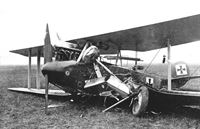
| Ago C.IV with personal markings, probably from FA 68, rare for the type. Of course, the photos are of a crash.
|
 |
J.Herris - Otto, AGO and BFW Aircraft of WWI /Centennial Perspective/ (37)
|
|
|
 |
J.Herris - Otto, AGO and BFW Aircraft of WWI /Centennial Perspective/ (37)
|
| Ago C.IV(Schul) 55xx/16 from Flieger-Abteilung 47 after a heavy landing. It was in the final production configuration common to Schutte-Lanz-built aircraft - fixed fin, ailerons on all wings connected by an actuating strut, and the diagonal strut adding additional strength to the outer interplane strut bracing. (Bruno Schmaling)
|
 |
J.Herris - Otto, AGO and BFW Aircraft of WWI /Centennial Perspective/ (37)
|
| Ago C.IV in the final production configuration down off the aerodrome. (Bruno Schmaling)
|
 |
J.Herris - Otto, AGO and BFW Aircraft of WWI /Centennial Perspective/ (37)
|
| Ago C.IV from Flieger-Abteilung 47 after an accident that was too frequent for the type. (Bruno Schmaling)
|
 |
J.Herris - Otto, AGO and BFW Aircraft of WWI /Centennial Perspective/ (37)
|
| Another Ago C.IV from Flieger-Abteilung 47 after a bad landing. It was in the final production configuration common to Schutte-Lanz-built aircraft - fixed fin, ailerons on all wings connected by an actuating strut, and the diagonal strut adding additional strength to the outer interplane strut bracing and may have been built by Schutte-Lanz. Unfortunately, the nose is badly damaged and we cannot tell if it had an Ago logo. These types of accidents were too common with the Ago C.IV and resulted in its bad reputation. In contrast, the contemporary DFW C.V, although much slower than the Ago C.IV, was far more popular with crews due to its good maneuverability and handling qualities, and crews far preferred its safety to the greater speed of the Ago C.IV. (Bruno Schmaling)
|
 |
J.Herris - Otto, AGO and BFW Aircraft of WWI /Centennial Perspective/ (37)
|
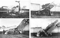
| Accident photos of several early-production Ago C.IVs from Flieger-Abteilung (A) 296. These types of accidents were too common with the Ago C.IV as illustrated here and resulted in its bad reputation. (Bruno Schmaling)
|
 |
J.Herris - Otto, AGO and BFW Aircraft of WWI /Centennial Perspective/ (37)
|
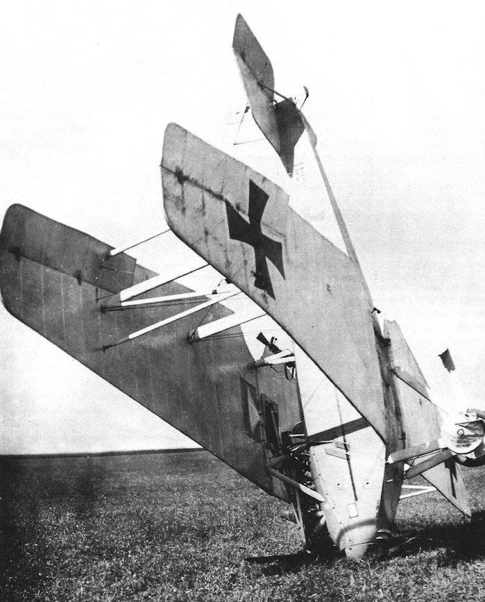
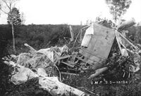
| Remains of an Ago C.IV totally destroyed in an accident. (Peter M. Grosz Collection/STDB)
|
 |
J.Herris - Otto, AGO and BFW Aircraft of WWI /Centennial Perspective/ (37)
|
|
|
 |
Журнал - Flight за 1917 г.
|
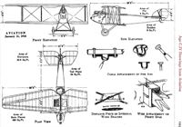
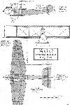
| THE AGO BIPLANE. - Some general views. Top: three-quarter front view. The openings in the top plane for the radiator and petrol service tank should be noted. Bottom: view from above, showing in diagrammatic form the construction of top plane. Inset: the tail planes.
|
 |
Журнал - Flight за 1917 г.
|
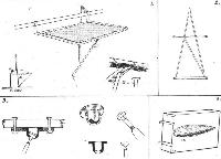
| THE AGO BIPLANE. - Some constructional details. 1. The gunner's seat. 2. The rear cabane. 3. A cable attachment extensively employed on the Ago. The cup-shaped socket is machined out of the solid, and has a slot through which passes the shank of the strainer. Three-ply packing is placed between the plate of the fitting and the base so as to make up the thickness of the socket. 4. The petrol service tank lying on its side on the floor. When in place on the machine it is carried in the opening in the upper wing to the left of the cabane.
|
 |
Журнал - Flight за 1917 г.
|
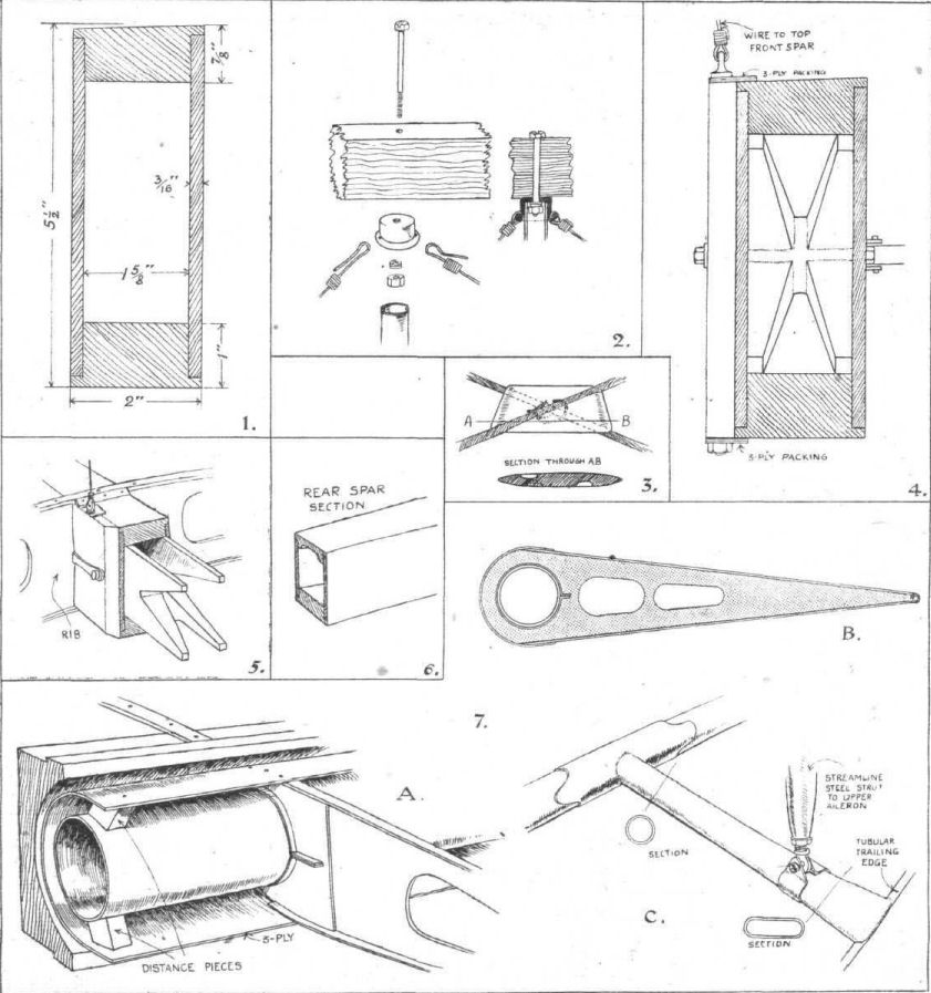
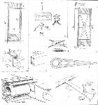
| THE AGO BIPLANE. - More Constructional Details. 1. Dimensions of lower front spar near body. 2. Attachment of tubular struts to fuselage longerons. 3. The hardwood distance piece at the crossing of the internal wing-bracing cables. 4. Section of the lower front spar at the point of attachment of the inter-plane wire. 5. Perspective sketch of same joint. 6. Section of rear spar. 7. (A) construction of false spar and aileron leading edge; (B) An aileron rib (not to scale); (C) Aileron crank and attachment of inter-aileron strut.
|
 |
J.Herris - Otto, AGO and BFW Aircraft of WWI /Centennial Perspective/ (37)
|
|
|
 |
J.Herris - Otto, AGO and BFW Aircraft of WWI /Centennial Perspective/ (37)
|
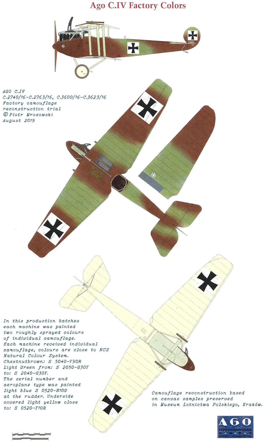
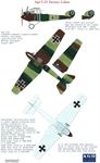
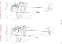
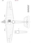
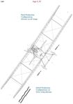
| AGO C.IV C.2740/16-C.2763/16, C.3600/16-C.3623/16 Factory camouflage reconstruction trial
|
 |
J.Herris - Otto, AGO and BFW Aircraft of WWI /Centennial Perspective/ (37)
|
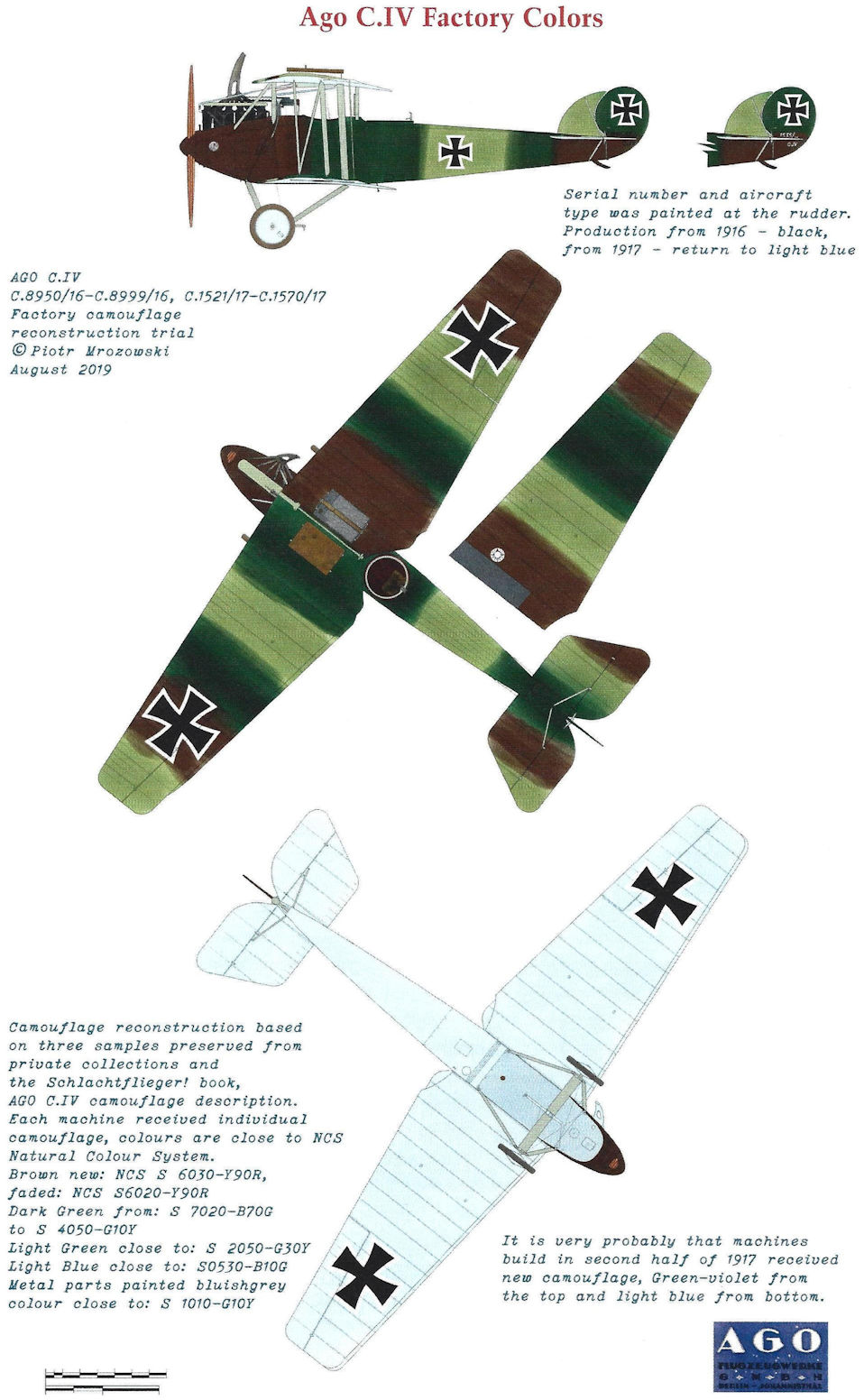
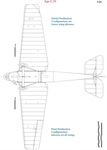
| AGO C.IV C.8950/16-C.8999/16, C.1521/17-C.1570/17 Factory camouflage reconstruction trial
|
 |
J.Herris - Otto, AGO and BFW Aircraft of WWI /Centennial Perspective/ (37)
|
|
|
 |
O.Thetford, P.Gray - German Aircraft of the First World War /Putnam/
|
|
|
 |
Журнал - Flight за 1917 г.
|
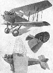
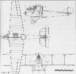
| A CAPTURED AGO BIPLANE. - Plan, side and front elevations to scale.
|
 |
J.Herris - Otto, AGO and BFW Aircraft of WWI /Centennial Perspective/ (37)
|
| Ago C.IV
|
 |
J.Herris - Otto, AGO and BFW Aircraft of WWI /Centennial Perspective/ (37)
|
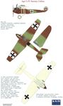
| Ago C.IV
|
 |
J.Herris - Otto, AGO and BFW Aircraft of WWI /Centennial Perspective/ (37)
|
| Ago C.IV
|
 |
J.Herris - Otto, AGO and BFW Aircraft of WWI /Centennial Perspective/ (37)
|
| Ago C.IV
|