
Книги
Putnam
S.Ransom, R.Fairclough
English Electric Aircraft and their Predecessors
58
S.Ransom, R.Fairclough - English Electric Aircraft and their Predecessors /Putnam/
The first of the Syndicate's own designs, known as the ASL Monoplane had the distinction of being the first full-scale aircraft of canard layout to fly in the British Isles. Designed by Barber and based on his experiments with model aircraft, it was built by Howard Wright and W.O. Manning at the Battersea workshops, during January and February 1910. On Sunday, March 6, with Bert Woodrow, the Syndicate's test pilot, at the controls the ASL Monoplane made its first flight, over Durrington Downs. Before the flight the pilot slowly taxied the machine for about ten minutes and with a following wind proceeded to take off. The aircraft left the ground in about 40-50 yards and rose steadily on an even keel to a height of 25-30 feet. After flying steadily for a short time, Woodrow switched off the engine, and in doing so let the monoplane land with a sideways swing, damaging a wing and the undercarriage. Repairs were put in hand and the aircraft later made further successful flights. This monoplane's fuselage, unlike that of its predecessor, was a wooden, wire-braced structure of rectangular section. A single 60 hp Green engine, driving a two-blade pusher propeller designed by Manning, was mounted aft of the pilot and passenger, the pilot being seated just forward of the wing leading edge and the passenger immediately behind him. The wings were tapered in plan and had a deep aerofoil section of heavy camber set at a small angle of incidence. The rear spar of the wing was pivoted to the fuselage to assist foot operated warping control. Pegamoid cloth covered both wing surfaces. The foreplane was fixed with a relatively large angle of incidence and was fitted with end-elevators which, like the small rudder mounted above the foreplane were operated by hand levers placed on either side of the pilot. The main undercarriage was sprung on the Farman principle and was supplemented by a pair of nosewheels and wingtip wheels reminiscent of the 1909 Biplane.
At this juncture it seems a disagreement arose between Barber and Wright, which led to the Syndicate's severing connections with Wright's business. Subsequently, the Syndicate put into production the fairly successful Valkyrie monoplane, on which Barber gained his aviator's certificate No. 30 issued on 22 November, 1910.
ASL Monoplane
Span 42 ft; length 31 ft; foreplane span 12 ft; wing root chord 10 ft; wingtip chord 6 ft; wing root thickness 8 m; wing dihedral. 2° 18'; foreplane chord 3 ft; elevator span each 3 ft; propeller diameter 8 ft; propeller pitch 2 ft; wing area 310 sq ft; foreplane area including elevators 36 sq ft; total elevator area 18 sq ft.
Weight empty 802 lb.
Cruising speed 35 mph.
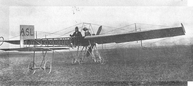
ASL monoplane No.2. Bert Woodrow at the controls of ASL Monoplane during trials on Durrington Downs in March 1910. This 1910 monoplane built by Howard Wright for Horatio Barber was not a success.

Howard Wright's original drawing of the swivelling propeller mechanism for Maj BadenPowell's aeroplane.
The Barber and Aeronautical Syndicate Monoplanes
Horatio Claude Barber returned to England from Paris, where he had been leading a somewhat leisurely life, early in 1908 fired with enthusiasm to design and build his own aeroplane, as a result of his visit to an exhibition of flying machines held at the Grand Palais. On his return according to his own reminiscences, he found a suitable workshop in some disused railway arches at Battersea and there began construction but, lacking engineering knowledge, entrusted the work to a consulting engineer. This engineer was Howard Wright.
The resultant two-seat monoplane was powered by a 50 h.p. Antoinette water-cooled engine driving contra-rotating propellers, the last feature possibly giving the rise to or being derived from that incorporated in Seton-Karr biplane which was under construction at about the same time. The monoplane's fuselage had a welded steel-tube structure, its only covering being provided by the Antoinette's radiators which occupied the full depth and almost the entire length of each of its sides. The wings were moderately cambered and were tapered over the majority of their span, the intermost portions being of parallel chord. They were hinged at the fuselage sides and interconnected by a system of bracing wires passing through the apexes of kingposts so that their dihedral would be self-adjusting according to flight conditions. This idea on automatic lateral stability was incorporated in patent No. 1999 filed by Barber in January 1909. Wing-warping control was apparently superimposed on dihedral movement, although it seems that the original intention was to fit full-chord wingtip ailerons. Longitudinal and directional controls were provided, respectively, by lever-operated elevators fitted to the ends of the tailplane, and a triangular rudder. The pilot sat in line with the wing's trailing edge and the passenger was placed ahead of him. The undercarriage consisted of two mainwheels attached to a transverse, leaf-sprung axle fitted to a system of V-struts, and a sprung tailwheel. It seems that wingtip wheels also were initially fitted but that these were discarded before or during the first tests. The monoplane was completed and delivered in the first week of June 1909 to Larkhill on Durrington Downs, where Barber had erected a shed to house it.
Meanwhile, the Aeronautical Syndicate Ltd had been formed in the preceding April. The directors and only shareholders at that time were Charles Worsley Battersby and Herman Rudolph Schmettau. The former was a stockbroker of the partnership of R.C. May and Battersby and the latter a solicitor of the firm of Hays, Schmettau and Dunn, who appear to have acted for Barber and provided him with a poste restante address at that time. Barber was the Syndicate's general manager but he never became a shareholder. At the formation of the company Barber sold it his patents, monoplane and hangar, by which it might be inferred that the Syndicate provided him with the finance necessary for him to continue his experiments.
During the course of the monoplane's trials several modifications were incorporated: the fuselage was completely covered; a triangular fin and rectangular rudder were added; a different form of elevator was fitted and a second tailplane was included above the fuselage immediately behind the pilot. The trials were unsuccessful, however, and the monoplane was subsequently dismantled.
Barber Monoplane
Span 32 ft; length 27 ft; wing area 200 sq ft.
Weight loaded 1,000 lb.
Coventry Ordnance Works Military Trials Biplanes
During the summer of 1911, Col J.E.B. Seely, Under Secretary for War, announced that the War Office was considering offering prizes for an aeroplane suitable for military use. By October, plans for a competition were being formed, and early in December, an Aeronautical Society meeting, held at the Royal United Services Institute, London, provided an opportunity for open discussion between the Army and aircraft constructors regarding the requirements of military aircraft. Among those present at the meeting were W.O. Manning and Howard T. Wright, representing the Coventry Ordnance Works Ltd, which had just taken over Wright's business under the railway arches at Battersea. The meeting proved so successful that a second one was arranged but before this took place the War Office announced the conditions and prizes for its competition to be held at Larkhill in August 1912. The directors of the Coventry Ordnance Works, on hearing the details of the competition, decided to enter aircraft for what became known as the Military Trials and accordingly authorised Manning and Wright to proceed with the design and manufacture of suitable machines.
Manning set to work immediately after the decision had been made and soon produced two designs, both of unequal-span tractor biplanes, one having its two crew seated side-by-side and the other with its two crew seated in tandem. Powerplants chosen were the 100 hp Gnome, fourteen-cylinder rotary and the 110 hp Chenu inline water-cooled engine. Their installation was decided from consideration of frontal area and the Chenu engine was therefore fitted to the tandem-seat design, which had a narrow fuselage with a short rounded top-decking immediately behind the open cockpit. The fuselage of the Gnome-powered biplane was untapered in plan and necessarily broad but tapered rearwards in side elevation two faired head-rests being provided for the crew. Both machines had their fuselages mounted above the lower wing, which was attached at its centre-section by four pairs of short struts, the centre pairs forming a framework for a streamline fairing that enclosed the petrol tank. The upper wing of each biplane was carried solely by four pairs of interplane-struts and was made in five sections. The outboard sections of the upper wing were braced from kingposts and could be warped for lateral control. The wings of the Gnome-powered biplane were tapered in plan and those of the other machine were of parallel chord. There was no centre-section cut-out in either wing of the Gnome-powered aircraft when it first appeared at Brooklands but they were incorporated within a month of its debut. The fixed tail surfaces of the Gnome-engined aircraft were semi-elliptical in planform, and those of the other of triangular shape. The elevators, fin and rudder of the two machines were distinctive in arrangement. The Gnome-powered biplane had three-quarter circular elevators, with the forward quarter forming a horn-balance, small twin triangular fins, each mounted in line with the fuselage sides, and twin elliptically-shaped rudders, which each had two horn-balances. The Chenu version had a single triangular fin and horn-balanced rudder and elevators of shark's fin shape. Each machine's undercarriage was unsprung and relied upon its low-pressure balloon tyres to absorb landing shocks.
Construction of the Gnome-powered Military Trials Biplane started at Battersea early in 1912 with the manufacture and assembly of its fuselage, the metal fittings for which were made at COW's factory at Coventry. The fuselage was a wire-braced box-girder structure with four ash longerons and spruce spacing-struts. The forward ends of the longerons were bent using steam and fitted into two steel pressings, which carried the engine and propeller shaft, the latter being mounted above and driven by a 1 1/2 in Renold roller chain through a 2: 1 reduction gear from the engine. The Gnome engine was fitted with Bosch dual ignition and could be started from the cockpit. Nine laminations of teak were used for the Manning-designed two-blade propeller, the inner region of which gave low thrust to reduce drag and pilot discomfort from the slipstream. The propeller hub had the additional refinement of a spinner. Engine and nose fuselage cowling was cut from sheet aluminium and attached by means of car-hood fasteners. A 10 Imp gal gravity petrol tank and a 22 Imp gal oil tank were carried in the bay behind the engine, the gravity tank being supplied with fuel pumped from the 40 Imp gal tank carried in the fairing between the fuselage and lower-wing centre-section.
Pilot's controls comprised a wheel at the top of a pivoted control column and a rudder bar. Dual rudder control was later installed. Both wings were built-up on two I-section ash spars and a thinner intermediate spar, and had solid ribs of Eiffel No. 8 aerofoil section, lightened with holes between the spars. The fabric-covered wings were internally braced by wires, inspection of their joints and those of the spars being made through sliding aluminium panels. Interplane-struts and kingposts were of streamline section and made from silver spruce. Stranded cable was used for external bracing and warping wires, the latter passing through pulleys housed in streamline fairings. All tail surfaces had flat wooden frameworks and were fabric covered. Undercarriage and nose skid struts were made of Honduras mahogany, the skid itself being of hickory. A small tusk was fitted inboard of each spoked wheel to prevent the apex of each undercarriage leg from digging into the ground in the event of the spokes breaking. The tailskid was of bent cane and was fitted with a simple but effective braking device, comprising a spring-steel claw which was always operative unless drawn clear of the ground by the pilot pulling the wire attached to it and fastening this to a hook near his seat.
About the end of April 1912, the components of the Gnome-powered biplane were taken to Brooklands and there assembled in hangar No.32, which had also been taken over by COW from Howard Wright. Its debut at Brooklands created considerable interest and an aviation journalist writing for Aeronautics was later to record: 'In strength, in neatness and finish of design, in minute attention to detail, nothing finer than this splendid biplane has ever been produced m the country.' The biplane's first flight was made shortly afterwards by T.O.M. Sopwith, whose services as test pilot had been secured by COW. The flight was successful, Sopwith being particularly impressed by the machine's remarkable rate of climb, and was soon followed by a second with Manning as passenger. On the following day, the biplane was entered for an impromptu take-off competition and cross-country race held at Brooklands, Sopwith taking three passengers aloft for the first event, two of the passengers sitting at each side of the fuselage on the lower wing. From this time the biplane was nicknamed, Wombus (W.O. Manning's omnibus). The biplane was flown throughout the summer in preparation for the Military Trials but persistent trouble was experienced with the chain drive to the propeller, which resulted in the fitting of three 1-in roller chains instead of the single chain. Elevator area was also found to be inadequate and was increased.
With the completion of the first COW biplane, construction of the Chenu-powered version progressed more quickly but this was not delivered to Brooklands until July 1912, when it was tested by Sopwith. The second biplane's structure was similar to the first, changes being dictated by the biplane's configuration only. Besides having a smaller span, the fuselage was shortened by the removal of one bay behind the cockpit. The fuselage was also mounted higher in the wing gap since the propeller was directly driven and propeller ground clearance had to be maintained without lengthening the undercarriage legs. The Chenu engine was fully cowled and its radiators were mounted on each side of the forward cockpit. A four-blade propeller, made from a pair of superimposed two-blade propellers, was fitted, this somewhat unusual arrangement possibly arising from the transport and crating requirements of the Military Trials, although Manning may have considered the economics of being able to replace one two-blade propeller in the event of damage. The only other noticeable changes were the fitting of two short skids behind the undercarriage wheels and skids below the lower wingtips.
The first COW Biplane, which had been allotted Trials No. 10, arrived at Larkhill in good time for the start of the Military Trials but its sister machine, given Trials No.11, had not reached Larkhill by 31 July, the stipulated deadline for all competitors. It had been delayed in its journey by road but despite its late arrival, was not disqualified from the competition. The Trials included twelve tests of which No.10 attempted only the first three, covering constructional requirements, quick assembly tests and the three-hour test, and No.11 failed to compete owing to engine trouble. In the quick assembly test No. 10 came fourteenth, five men taking 1 hr 51 min 45 sec to assemble the biplane ready for flight. The three-hour test was attempted on 22 August with F.P. Raynham at the controls but was abandoned after one hour when he was forced to land owing to a leak in the pressure pump, which transferred fuel from the ventral tank to the gravity tank. Further trouble with the propeller of No.10 prevented it from entering more of the tests. Unfortunately, Manning was abroad at the time these difficulties were encountered, and it was not until his return, late in August after the Trials, that he was able to investigate the faults. Howard Wright had left the Coventry Ordnance Works, about this time, to become chief designer to J. Samuel White & Co Ltd, of Cowes.
Further test flights with No. 10 made at Brooklands, where both biplanes returned after the Trials, were unsatisfactory and led Manning to modify the machine using as many of the original components as possible. The modified biplane bore a slight resemblance to No.10 owing to the use of the latter's fuselage, fixed tail surfaces and rudder. The Gnome engine installation was retained but a new propeller of the same diameter was made. New wings of increased and unequal span and constant chord were fitted together with elevators of larger area. The upper-wing had inversely-tapered split ailerons and was carried by eight pairs of interplane-struts of reduced length, the lower-wing being attached close to the lower surface of the fuselage. The undercarriage legs were lengthened to maintain propeller ground clearance and again balloon tyres were used.
Reconstruction of No. 10 was undertaken late in 1912 and the modified biplane was flown for the first time, by Raynham at Brooklands on 13 January, 1913. The new biplane proved more successful than the original but the chain drive to the propeller still gave trouble. A smaller diameter two-blade propeller was fitted directly to the engine, and, at the same time, the engine cowling was reshaped by the addition of two rounded fairings on each side of the propeller attachment. Thereafter the biplane was flown successfully throughout 1913.
The fate of No. 11 remains unknown.
No.10
Span: upper 40 ft, lower 24 ft 8 in; overall length 33 ft 3 in; height 12 ft 8 in; wing root chord upper and lower 6 ft; wingtip chord: upper 4 ft 6 in, lower 5 ft 2 in; gap 8 ft; tailplane span excluding elevators 8 ft, tail plane root chord 7 ft 10 m;. elevator span: original 4 ft, final 5 ft. 3 m, maximum elevator chord 3 ft 4 in; rudder height 4 ft; maximum rudder chord 3 ft, propeller diameter 11 ft 6 m; undercarriage track 6 ft 9 in; wheel diameter 2 ft 10 in; wing area: original 336.7 sq ft, final 319.7 sq ft; tailplane area excluding elevators 30.9 sq ft; total elevator area: original 17.3 sq ft, final 27.4 sq ft; total fin area 4 sq ft; total rudder area 15.6 sq ft.
Weight empty 1,200 lb; weight loaded 1,950 lb.
Maximum speed 60 mph; landing speed 20 mph.
No.10 Modified
Upper wing span 56 ft; wing area 630 sq ft.
Weight empty 1,100 lb; weight loaded 1,900 lb.
Maximum speed 60 mph; landing speed less than 20 mph.
No. 11
Span: upper 35 ft, lower 22 ft; overall length 31 ft 3 in; height 13 ft 2 in; wing chord upper and lower 5 ft 6 m; gap 8 ft; tailplane span excluding elevators 10 ft; tailplane root chord 6 ft 9 m, elevator span 6 ft 6 in; maximum elevator chord 4 ft; rudder height 5 ft 3 in; minimum rudder chord 4 ft 6 in; propeller diameter 11 ft 6 in; undercarriage track 6 ft 3 in; wheel diameter 2 ft 10 in; wing area 290.5 sq ft; tailplane area excluding elevators 35.8 sq ft; total elevator area 24 sq ft; fin area 4 sq ft; rudder area 108 sq ft
Weight empty 1,250 lb; weight loaded 2,050 lb.
Maximum speed 68-70 mph.
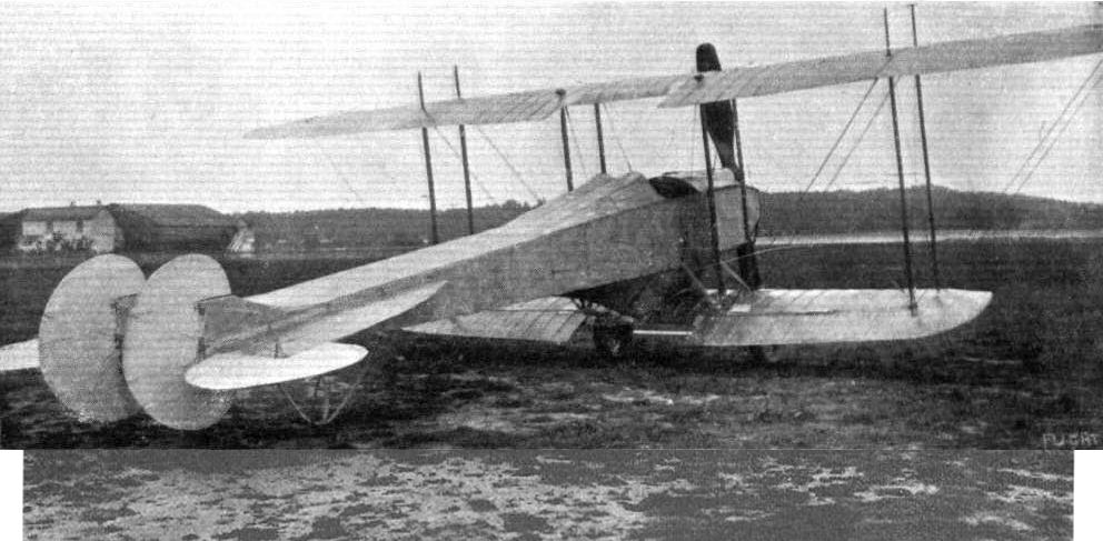
Coventry Ordnance Works Admiralty Type 54
In 1913, the Coventry Ordnance Works received contract No. CP 40633/13 from the Air Department of the Admiralty for one seaplane. It was powered by a 160 hp Gnome rotary, and allotted serial number 54. The seaplane was fitted with wireless and allotted the call sign NO6 in August 1913. No record has been found of the aircraft in Service or ever being completed.
During the summer of 1911, Col J.E.B. Seely, Under Secretary for War, announced that the War Office was considering offering prizes for an aeroplane suitable for military use. By October, plans for a competition were being formed, and early in December, an Aeronautical Society meeting, held at the Royal United Services Institute, London, provided an opportunity for open discussion between the Army and aircraft constructors regarding the requirements of military aircraft. Among those present at the meeting were W.O. Manning and Howard T. Wright, representing the Coventry Ordnance Works Ltd, which had just taken over Wright's business under the railway arches at Battersea. The meeting proved so successful that a second one was arranged but before this took place the War Office announced the conditions and prizes for its competition to be held at Larkhill in August 1912. The directors of the Coventry Ordnance Works, on hearing the details of the competition, decided to enter aircraft for what became known as the Military Trials and accordingly authorised Manning and Wright to proceed with the design and manufacture of suitable machines.
Manning set to work immediately after the decision had been made and soon produced two designs, both of unequal-span tractor biplanes, one having its two crew seated side-by-side and the other with its two crew seated in tandem. Powerplants chosen were the 100 hp Gnome, fourteen-cylinder rotary and the 110 hp Chenu inline water-cooled engine. Their installation was decided from consideration of frontal area and the Chenu engine was therefore fitted to the tandem-seat design, which had a narrow fuselage with a short rounded top-decking immediately behind the open cockpit. The fuselage of the Gnome-powered biplane was untapered in plan and necessarily broad but tapered rearwards in side elevation two faired head-rests being provided for the crew. Both machines had their fuselages mounted above the lower wing, which was attached at its centre-section by four pairs of short struts, the centre pairs forming a framework for a streamline fairing that enclosed the petrol tank. The upper wing of each biplane was carried solely by four pairs of interplane-struts and was made in five sections. The outboard sections of the upper wing were braced from kingposts and could be warped for lateral control. The wings of the Gnome-powered biplane were tapered in plan and those of the other machine were of parallel chord. There was no centre-section cut-out in either wing of the Gnome-powered aircraft when it first appeared at Brooklands but they were incorporated within a month of its debut. The fixed tail surfaces of the Gnome-engined aircraft were semi-elliptical in planform, and those of the other of triangular shape. The elevators, fin and rudder of the two machines were distinctive in arrangement. The Gnome-powered biplane had three-quarter circular elevators, with the forward quarter forming a horn-balance, small twin triangular fins, each mounted in line with the fuselage sides, and twin elliptically-shaped rudders, which each had two horn-balances. The Chenu version had a single triangular fin and horn-balanced rudder and elevators of shark's fin shape. Each machine's undercarriage was unsprung and relied upon its low-pressure balloon tyres to absorb landing shocks.
Construction of the Gnome-powered Military Trials Biplane started at Battersea early in 1912 with the manufacture and assembly of its fuselage, the metal fittings for which were made at COW's factory at Coventry. The fuselage was a wire-braced box-girder structure with four ash longerons and spruce spacing-struts. The forward ends of the longerons were bent using steam and fitted into two steel pressings, which carried the engine and propeller shaft, the latter being mounted above and driven by a 1 1/2 in Renold roller chain through a 2: 1 reduction gear from the engine. The Gnome engine was fitted with Bosch dual ignition and could be started from the cockpit. Nine laminations of teak were used for the Manning-designed two-blade propeller, the inner region of which gave low thrust to reduce drag and pilot discomfort from the slipstream. The propeller hub had the additional refinement of a spinner. Engine and nose fuselage cowling was cut from sheet aluminium and attached by means of car-hood fasteners. A 10 Imp gal gravity petrol tank and a 22 Imp gal oil tank were carried in the bay behind the engine, the gravity tank being supplied with fuel pumped from the 40 Imp gal tank carried in the fairing between the fuselage and lower-wing centre-section.
Pilot's controls comprised a wheel at the top of a pivoted control column and a rudder bar. Dual rudder control was later installed. Both wings were built-up on two I-section ash spars and a thinner intermediate spar, and had solid ribs of Eiffel No. 8 aerofoil section, lightened with holes between the spars. The fabric-covered wings were internally braced by wires, inspection of their joints and those of the spars being made through sliding aluminium panels. Interplane-struts and kingposts were of streamline section and made from silver spruce. Stranded cable was used for external bracing and warping wires, the latter passing through pulleys housed in streamline fairings. All tail surfaces had flat wooden frameworks and were fabric covered. Undercarriage and nose skid struts were made of Honduras mahogany, the skid itself being of hickory. A small tusk was fitted inboard of each spoked wheel to prevent the apex of each undercarriage leg from digging into the ground in the event of the spokes breaking. The tailskid was of bent cane and was fitted with a simple but effective braking device, comprising a spring-steel claw which was always operative unless drawn clear of the ground by the pilot pulling the wire attached to it and fastening this to a hook near his seat.
About the end of April 1912, the components of the Gnome-powered biplane were taken to Brooklands and there assembled in hangar No.32, which had also been taken over by COW from Howard Wright. Its debut at Brooklands created considerable interest and an aviation journalist writing for Aeronautics was later to record: 'In strength, in neatness and finish of design, in minute attention to detail, nothing finer than this splendid biplane has ever been produced m the country.' The biplane's first flight was made shortly afterwards by T.O.M. Sopwith, whose services as test pilot had been secured by COW. The flight was successful, Sopwith being particularly impressed by the machine's remarkable rate of climb, and was soon followed by a second with Manning as passenger. On the following day, the biplane was entered for an impromptu take-off competition and cross-country race held at Brooklands, Sopwith taking three passengers aloft for the first event, two of the passengers sitting at each side of the fuselage on the lower wing. From this time the biplane was nicknamed, Wombus (W.O. Manning's omnibus). The biplane was flown throughout the summer in preparation for the Military Trials but persistent trouble was experienced with the chain drive to the propeller, which resulted in the fitting of three 1-in roller chains instead of the single chain. Elevator area was also found to be inadequate and was increased.
With the completion of the first COW biplane, construction of the Chenu-powered version progressed more quickly but this was not delivered to Brooklands until July 1912, when it was tested by Sopwith. The second biplane's structure was similar to the first, changes being dictated by the biplane's configuration only. Besides having a smaller span, the fuselage was shortened by the removal of one bay behind the cockpit. The fuselage was also mounted higher in the wing gap since the propeller was directly driven and propeller ground clearance had to be maintained without lengthening the undercarriage legs. The Chenu engine was fully cowled and its radiators were mounted on each side of the forward cockpit. A four-blade propeller, made from a pair of superimposed two-blade propellers, was fitted, this somewhat unusual arrangement possibly arising from the transport and crating requirements of the Military Trials, although Manning may have considered the economics of being able to replace one two-blade propeller in the event of damage. The only other noticeable changes were the fitting of two short skids behind the undercarriage wheels and skids below the lower wingtips.
The first COW Biplane, which had been allotted Trials No. 10, arrived at Larkhill in good time for the start of the Military Trials but its sister machine, given Trials No.11, had not reached Larkhill by 31 July, the stipulated deadline for all competitors. It had been delayed in its journey by road but despite its late arrival, was not disqualified from the competition. The Trials included twelve tests of which No.10 attempted only the first three, covering constructional requirements, quick assembly tests and the three-hour test, and No.11 failed to compete owing to engine trouble. In the quick assembly test No. 10 came fourteenth, five men taking 1 hr 51 min 45 sec to assemble the biplane ready for flight. The three-hour test was attempted on 22 August with F.P. Raynham at the controls but was abandoned after one hour when he was forced to land owing to a leak in the pressure pump, which transferred fuel from the ventral tank to the gravity tank. Further trouble with the propeller of No.10 prevented it from entering more of the tests. Unfortunately, Manning was abroad at the time these difficulties were encountered, and it was not until his return, late in August after the Trials, that he was able to investigate the faults. Howard Wright had left the Coventry Ordnance Works, about this time, to become chief designer to J. Samuel White & Co Ltd, of Cowes.
Further test flights with No. 10 made at Brooklands, where both biplanes returned after the Trials, were unsatisfactory and led Manning to modify the machine using as many of the original components as possible. The modified biplane bore a slight resemblance to No.10 owing to the use of the latter's fuselage, fixed tail surfaces and rudder. The Gnome engine installation was retained but a new propeller of the same diameter was made. New wings of increased and unequal span and constant chord were fitted together with elevators of larger area. The upper-wing had inversely-tapered split ailerons and was carried by eight pairs of interplane-struts of reduced length, the lower-wing being attached close to the lower surface of the fuselage. The undercarriage legs were lengthened to maintain propeller ground clearance and again balloon tyres were used.
Reconstruction of No. 10 was undertaken late in 1912 and the modified biplane was flown for the first time, by Raynham at Brooklands on 13 January, 1913. The new biplane proved more successful than the original but the chain drive to the propeller still gave trouble. A smaller diameter two-blade propeller was fitted directly to the engine, and, at the same time, the engine cowling was reshaped by the addition of two rounded fairings on each side of the propeller attachment. Thereafter the biplane was flown successfully throughout 1913.
The fate of No. 11 remains unknown.
No.10
Span: upper 40 ft, lower 24 ft 8 in; overall length 33 ft 3 in; height 12 ft 8 in; wing root chord upper and lower 6 ft; wingtip chord: upper 4 ft 6 in, lower 5 ft 2 in; gap 8 ft; tailplane span excluding elevators 8 ft, tail plane root chord 7 ft 10 m;. elevator span: original 4 ft, final 5 ft. 3 m, maximum elevator chord 3 ft 4 in; rudder height 4 ft; maximum rudder chord 3 ft, propeller diameter 11 ft 6 m; undercarriage track 6 ft 9 in; wheel diameter 2 ft 10 in; wing area: original 336.7 sq ft, final 319.7 sq ft; tailplane area excluding elevators 30.9 sq ft; total elevator area: original 17.3 sq ft, final 27.4 sq ft; total fin area 4 sq ft; total rudder area 15.6 sq ft.
Weight empty 1,200 lb; weight loaded 1,950 lb.
Maximum speed 60 mph; landing speed 20 mph.
No.10 Modified
Upper wing span 56 ft; wing area 630 sq ft.
Weight empty 1,100 lb; weight loaded 1,900 lb.
Maximum speed 60 mph; landing speed less than 20 mph.
No. 11
Span: upper 35 ft, lower 22 ft; overall length 31 ft 3 in; height 13 ft 2 in; wing chord upper and lower 5 ft 6 m; gap 8 ft; tailplane span excluding elevators 10 ft; tailplane root chord 6 ft 9 m, elevator span 6 ft 6 in; maximum elevator chord 4 ft; rudder height 5 ft 3 in; minimum rudder chord 4 ft 6 in; propeller diameter 11 ft 6 in; undercarriage track 6 ft 3 in; wheel diameter 2 ft 10 in; wing area 290.5 sq ft; tailplane area excluding elevators 35.8 sq ft; total elevator area 24 sq ft; fin area 4 sq ft; rudder area 108 sq ft
Weight empty 1,250 lb; weight loaded 2,050 lb.
Maximum speed 68-70 mph.
Coventry Ordnance Works Admiralty Type 54
In 1913, the Coventry Ordnance Works received contract No. CP 40633/13 from the Air Department of the Admiralty for one seaplane. It was powered by a 160 hp Gnome rotary, and allotted serial number 54. The seaplane was fitted with wireless and allotted the call sign NO6 in August 1913. No record has been found of the aircraft in Service or ever being completed.
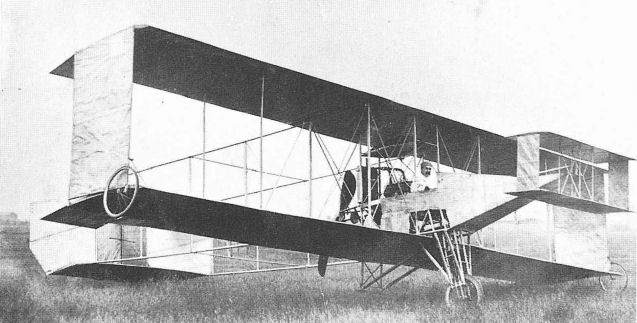
COW's entry for the 1912 Military Trials, later given Trials No.10, making its debut at Brooklands in April. Note the early form of the wings without centre-section cut-outs.
Biplane No.10 at Larkhill in August 1912.
Biplane No.10 at Brooklands. Note revised wing form.

Biplane No.10 Modified, Brooklands, January 1913.

Fuselage for Biplane No. 10 under construction at Battersea early in 1912.

Biplane No.11 with pilot and ground crew at Larkhill.
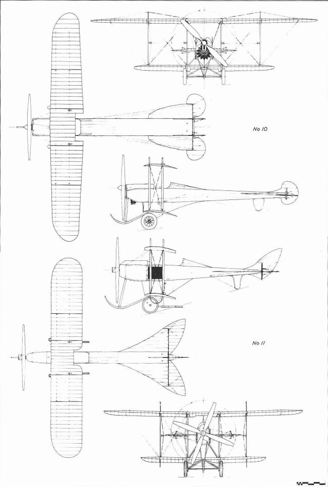
Coventry Ordnance Works 1912 Military Trials Biplanes.
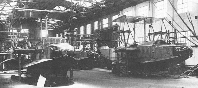
Felixstowe F.3 production at the United Electric Car Works, Preston, which had been taken over by Dick, Kerr & Co late in 1917. This photograph was taken about July 1918.

Components of the automatic pilot made by the Phoenix Dynamo Co and believed fitted to Felixstowe F.3 N4409 (c/n 208) for trials. The main attitude-sensing devices were mercury-filled circular tubes which acted as switches for electrically-operated compressed-air flying controls.
Howard Wright 1909 Biplane
In December 1908, Malcolm H. Seton-Karr placed an order with Howard Wright for a biplane. Construction of the machine started immediately and it was completed in time for exhibition at the 1909 Olympia Aero Show, where it was acclaimed for its outstanding workmanship. The aircraft was noteworthy, also, for its strikingly clean appearance, indicating that contemporary aerodynamic theory had been applied with a degree of success, particularly by the introduction of a number of refinements to reduce drag. Clearly, this biplane was in advance of its time.
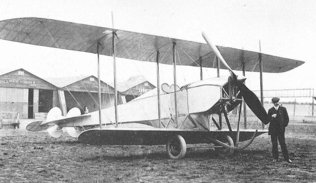
The biplane shown at Olympia followed Voisin lines but incorporated a streamlined nacelle for the comfort of the pilot. The nacelle was made of steel tubes welded together without sockets - a technique perfected in the course of constructing Capone's helicopters - and covered with silver doped fabric. At the aft end of the nacelle, a Belgian Metallurgique engine of 50 hp drove contra-rotating co-axial propellers through a patented 3:1 reduction gear, the forward propeller having blades of larger chord than the rear. A theoretical efficiency of 73 per cent was claimed for the propeller arrangement. The blades, which were made with constant incidence over their length, were of wood attached to steel shanks clamped offset to the propeller shaft. Petrol was gravity fed to the engine from a 15 Imp gal streamlined tank carried, like the radiator, between the interplane struts supporting the wing centre-section. The wings each had two ash spars reinforced with flitches of strip steel, and closely pitched ribs of spruce. The upper and lower surfaces of both wings were covered with fabric tautened with clear dope. No internal wing bracing was fitted, reliance being placed on spar stiffness. External bracing wires, streamlined interplane struts and fabric-covered end-plates maintained the wings in position. Construction of the forward elevator and fixed tailplane was similar to the wing, although the former dispensed altogether with bracing wires. The tail surfaces were carried on light tubular-steel booms braced with streamlined struts and wires. In addition to the forward elevator, operated by an irreversible screw from the cockpit, the biplane was controlled by four small wingtip ailerons connected through a closed-loop system of cables and struts joining corresponding pairs of ailerons, and a rudder mounted midway between the tailplane end-plates. The biplane was fitted with a monowheel undercarriage, based on the French REP monoplane, supplemented by wingtip wheels and a small tailwheel, this arrangement being considered to assist novice pilots to master the aircraft's controls before attempting flight. On the ground the biplane naturally rested on one of its wingtip wheels, in which state it remained until it had reached about 8 mph, when the machine would right itself onto an even keel. At 15 mph the tail was expected to lift, enabling the pilot to manoeuvre the biplane in any direction on its mainwheel so that he could familiarise himself with the controls without leaving the ground. Only when the pilot felt himself in control was he expected to increase his speed to about 30 mph for take-off.
After the Show the biplane was taken to Fambridge aerodrome, Essex, where Howard Wright had erected a shed to house it. The journey was not without mishap, however, for the dismantled biplane was badly damaged on two occasions when the waggon carrying the wings was driven into a railway bridge by an inattentive carter, and, later, when the tail booms of the fuselage were broken in manhandling the machine across a ditch on to the flying ground. Then the shed was blown down in a gale.
By the begining of May 1909, the biplane had been repaired and all was ready for engine tests. No trouble was experienced in starting the engine but, on warming up, it inexplicably gained speed to such an extent that the propeller shaft sheared and fragments of blades were hurled in all directions, even through the iron roof of the shed, buckling and breaking the tail booms yet again. Repairs were put in hand immediately and the middle of June saw the biplane at last being tested under the direction of W.O. Manning. As might have been foreseen, Seton-Karr experienced considerable difficulty with the undercarriage for it necessitated taxi-ing the machine to a speed higher than estimated to put it on an even keel, whilst keeping it on a straight course. These problems were overcome with perseverance and by the end of the month short hops of about 30 ft were achieved. The rough nature of the ground at Fambridge was not conducive to further success and the biplane was taken for more trials, to Camber Sands near Rye in Sussex, where it was still flying in November 1909.
Sometime during the course of repairs at Fambridge the biplane was modified to incorporate two small bogey wheels just aft of the main wheel and it was possibly the use of these wheels which led to achieving short hops with the aircraft. Other modifications included additional bracing of the mainwheel, the removal, along a diagonal, of the bottom rear corners of the tailplane end-plates as they were liable to damage during taxi-ing and the replacement of the contra-rotating propellers by a single pusher propeller.
More than one source of information suggests that Howard Wright built another biplane along similar lines to carry a pilot and two passengers. It may have been an aircraft like this which W.E. Cooke contemplated buying in September 1909 before finally ordering a monoplane from Howard Wright.
Span 40 ft; length 43 ft; height 10 ft 6 in; wing chord 6 ft 6 in; gap 6 ft 6 in; propeller diameter 8 ft; total surface area 620 sq ft.
Weight empty 1,100 lb; weight loaded 1,600 lb.
Cruising speed 35 mph.
Price ?1,200.
Howard Wright Glider
At the Battersea workshops, in June 1909, Howard Wright constructed a biplane glider which the technical press considered ideal for training purposes.
No detailed description of the glider or its subsequent history can be traced.
In December 1908, Malcolm H. Seton-Karr placed an order with Howard Wright for a biplane. Construction of the machine started immediately and it was completed in time for exhibition at the 1909 Olympia Aero Show, where it was acclaimed for its outstanding workmanship. The aircraft was noteworthy, also, for its strikingly clean appearance, indicating that contemporary aerodynamic theory had been applied with a degree of success, particularly by the introduction of a number of refinements to reduce drag. Clearly, this biplane was in advance of its time.
The biplane shown at Olympia followed Voisin lines but incorporated a streamlined nacelle for the comfort of the pilot. The nacelle was made of steel tubes welded together without sockets - a technique perfected in the course of constructing Capone's helicopters - and covered with silver doped fabric. At the aft end of the nacelle, a Belgian Metallurgique engine of 50 hp drove contra-rotating co-axial propellers through a patented 3:1 reduction gear, the forward propeller having blades of larger chord than the rear. A theoretical efficiency of 73 per cent was claimed for the propeller arrangement. The blades, which were made with constant incidence over their length, were of wood attached to steel shanks clamped offset to the propeller shaft. Petrol was gravity fed to the engine from a 15 Imp gal streamlined tank carried, like the radiator, between the interplane struts supporting the wing centre-section. The wings each had two ash spars reinforced with flitches of strip steel, and closely pitched ribs of spruce. The upper and lower surfaces of both wings were covered with fabric tautened with clear dope. No internal wing bracing was fitted, reliance being placed on spar stiffness. External bracing wires, streamlined interplane struts and fabric-covered end-plates maintained the wings in position. Construction of the forward elevator and fixed tailplane was similar to the wing, although the former dispensed altogether with bracing wires. The tail surfaces were carried on light tubular-steel booms braced with streamlined struts and wires. In addition to the forward elevator, operated by an irreversible screw from the cockpit, the biplane was controlled by four small wingtip ailerons connected through a closed-loop system of cables and struts joining corresponding pairs of ailerons, and a rudder mounted midway between the tailplane end-plates. The biplane was fitted with a monowheel undercarriage, based on the French REP monoplane, supplemented by wingtip wheels and a small tailwheel, this arrangement being considered to assist novice pilots to master the aircraft's controls before attempting flight. On the ground the biplane naturally rested on one of its wingtip wheels, in which state it remained until it had reached about 8 mph, when the machine would right itself onto an even keel. At 15 mph the tail was expected to lift, enabling the pilot to manoeuvre the biplane in any direction on its mainwheel so that he could familiarise himself with the controls without leaving the ground. Only when the pilot felt himself in control was he expected to increase his speed to about 30 mph for take-off.
After the Show the biplane was taken to Fambridge aerodrome, Essex, where Howard Wright had erected a shed to house it. The journey was not without mishap, however, for the dismantled biplane was badly damaged on two occasions when the waggon carrying the wings was driven into a railway bridge by an inattentive carter, and, later, when the tail booms of the fuselage were broken in manhandling the machine across a ditch on to the flying ground. Then the shed was blown down in a gale.
By the begining of May 1909, the biplane had been repaired and all was ready for engine tests. No trouble was experienced in starting the engine but, on warming up, it inexplicably gained speed to such an extent that the propeller shaft sheared and fragments of blades were hurled in all directions, even through the iron roof of the shed, buckling and breaking the tail booms yet again. Repairs were put in hand immediately and the middle of June saw the biplane at last being tested under the direction of W.O. Manning. As might have been foreseen, Seton-Karr experienced considerable difficulty with the undercarriage for it necessitated taxi-ing the machine to a speed higher than estimated to put it on an even keel, whilst keeping it on a straight course. These problems were overcome with perseverance and by the end of the month short hops of about 30 ft were achieved. The rough nature of the ground at Fambridge was not conducive to further success and the biplane was taken for more trials, to Camber Sands near Rye in Sussex, where it was still flying in November 1909.
Sometime during the course of repairs at Fambridge the biplane was modified to incorporate two small bogey wheels just aft of the main wheel and it was possibly the use of these wheels which led to achieving short hops with the aircraft. Other modifications included additional bracing of the mainwheel, the removal, along a diagonal, of the bottom rear corners of the tailplane end-plates as they were liable to damage during taxi-ing and the replacement of the contra-rotating propellers by a single pusher propeller.
More than one source of information suggests that Howard Wright built another biplane along similar lines to carry a pilot and two passengers. It may have been an aircraft like this which W.E. Cooke contemplated buying in September 1909 before finally ordering a monoplane from Howard Wright.
Span 40 ft; length 43 ft; height 10 ft 6 in; wing chord 6 ft 6 in; gap 6 ft 6 in; propeller diameter 8 ft; total surface area 620 sq ft.
Weight empty 1,100 lb; weight loaded 1,600 lb.
Cruising speed 35 mph.
Price ?1,200.
Howard Wright Glider
At the Battersea workshops, in June 1909, Howard Wright constructed a biplane glider which the technical press considered ideal for training purposes.
No detailed description of the glider or its subsequent history can be traced.
Seton-Karr at the controls of his Howard Wright 1909 Biplane at Fambridge. Note the modified undercarriage, two-blade pusher propeller and the removal of the corners of the tailplane end-plates.
Howard Wright 1909 biplane
Cooke Monoplane
On 4 September, 1909, the Burnley Express reported: 'An enterprising Burnley gentleman has given an order to Mr Howard T. Wright for one of his well-known biplanes. The machine is of the latest type being constructed of steel tubing, and having the most powerful engines [sic]. Strength has been the main consideration, and the machine, which is to carry three persons, will cost over ?1,000. The biplane is already constructed, but Mr Wright will not allow it to leave the testing grounds until it has had at least a fortnight's thorough test. The Burnley gentleman has gone to London to receive instructions under Mr Wright, and he will probably take charge of the machine when it arrives in Burnley. Mr Wright imposes certain conditions in respect of the sale, and one is that the biplane shall not be purely for exhibition purposes, but shall fly.'
The enterprising gentleman was W.E. Cooke, who had varied business interests in Lancashire besides being managing director of the Burnley Motor Pleasure Co, and his biplane was to be used to establish the Burnley & District Aero Club, of which his eighteen year-old son, Granville, was to act as secretary. Local response to the aero club was good and naturally the subject of much discussion, Howard Wright having consented to become the club's first honorary member. Plans were made for the biplane to be flown at the first Blackpool aviation meeting and to be entered for the Daily Mail prize of ?1 ,000 for the first circular flight of one mile by an all-British aeroplane. However, the club's immediate need was for a flying ground and though Howard Wright had twice visited Burnley to offer advice on this point, no suitable site was found in the vicinity. The club's promoters were forced to look elsewhere and after considering Freckleton Marsh, near Preston, finally rented land at Blackpool. The problem of the flying ground having been settled, another of finance arose, leading to various speculative reports that the biplane would not be bought after all. The doubts were quickly dispelled when it was announced that the East Lancashire Aeroplane Co, a syndicate headed by W.E. Cooke, had raised the purchase money by subscription, of which the largest amount had been contributed by Cooke. These difficulties had tended to delay the delivery of the aircraft but it finally arrived in Burnley on 9 October, 1909.
Shortly after placing his order, Cooke must have changed his mind as to the type of aircraft he proposed to buy, because the machine which was delivered was a monoplane. Cooke's intention to buy a monoplane was noted without explanation in the local press on 11 September. Undoubtedly, the change of order added to the delays, for a new aircraft had to be built. The monoplane was fitted with a single 50 hp Antoinette water-cooled engine driving a wooden two-blade propeller. The engine's long condenser radiators were attached along both sides of the fuselage. Petrol, sufficient for three hours' flight, was fed from the streamlined tank suspended from the cabane struts over the passenger, who sat well separated from the pilot within the fuselage which was built of light steel tubes. Warping control was applied to the tapered wings by means of foot pedals and the tailplane, fitted with end elevators, and a triangular rudder were operated from two small levers on either side of the pilot. The engine could be started by a small hand wheel placed on the pilot's left. The undercarriage followed Bleriot practice.
The aircraft, untested, was transported by rail to Manchester and from there to Burnley, where it arrived at 9 am, four hours later than expected. It was taken directly to the Athletic Grounds at Brunshaw, Burnley, and quickly erected for its exhibition which was to be opened at 10 am by the mayor. However, after erection some difficulty was experienced in starting the engine, it had become 'clogged up in transit.' These delays were Sufficient to postpone the opening of the exhibition until the afternoon, during the course of which the monoplane was taxied round the running track with the mayor as passenger. The aircraft remained on exhibition until 12 October, after which date it was proposed to show it at Wigan, Southport and Manchester before taking the aircraft to Blackpool for its first flight. These plans came to nothing and the aeroplane was displayed only at Accrington and Blackburn. At the last of the exhibitions, held in a large hall at Blackburn, the propeller came adrift, whilst the engine was being warmed-up, and broke up on hitting the high roof of the building, causing considerable damage. After the accident the engine also was declared beyond repair.
The mishap at Blackburn was followed by the demise of the Burnley & Distnct Aero Club and the disposal of the monoplane to the Northern Automobile Co, Bradford. This company advertised the aeroplane for sale at ?200 and in doing so claimed that it was unused! The monoplane was subsequently bought by Harold Keates Hales, who had it transported to Hanley on the outskirts of Stafford. There Hales exhibited it at at least two park fetes where he recovered in fees half the ?150 he paid for the monoplane. On 10 July, 1910, Hales took the aircraft to Keele Racecourse for its and his first flight. In attempting to take-off, however, he pulled back on the elevator control lever too sharply; the aircraft leapt into the air stalled and crashed to earth. Surprisingly, the monoplane was not totally wrecked and Hales escaped serious injury. The flight lasted 25 seconds.
A few months later the monoplane was again offered for sale the advertisement in The Aero of 12 October stating: 'Magnificent passenger-carrying Wright Monoplane, 50 hp Antoinette engine, not used, cost L1,000, bargain. H. Hales, Burslem.'
Span 32 ft; total surface area 240 sq ft.
Weight empty 750 lb; weight loaded 1,000 lb.
Estimated maximum speed 35 mph.
Price approximately ?1,000.
Howard Wright 1909 Monoplane and Lascelles Ornis
At least three 1909 Monoplanes, designed by Howard Wright, were made at the Battersea workshops during the period November-December 1909. The aircraft were notable for being the subject of one of the earliest British attempts to introduce mass-production techniques into aircraft manufacture, by having a standard structure, so that delivery could be guaranteed within fourteen days. Of the three, two were known to have been powered by the 35 hp Lascelles four-cylinder semi-radial air-cooled engine, although any engine of suitable power could be fitted to the customer's requirements. Features introduced with the Cooke monoplane were used in the design of the 1909 machine's undercarriage, tail unit, and also in the method of controlling the aircraft. However, the fuselage was made throughout of ash with steel angle-pieces and was wire-braced. The pilot, who sat level with the trailing-edges of the wings, which were of parallel-chord and had square tips, controlled the machine with two levers placed on either side of him. The right hand lever was used to warp the wings in conjunction with elevator movement and the left applied rudder. Contemporary records suggest that all the monoplanes were sold but do not state to whom.
A variant of the Monoplane was exhibited at the 1910 Olympia Aero Show Known as the Ornis it had been built for Richard Lascelles & Co Ltd, of 13 Greek Street, London, W.1, by Howard Wright in the month preceding the Show. The Ornis, with the exception of the rudder and method of control, was identical to the Lascelles-powered 1909 Monoplane, the rudder being rectangular in shape and the method of control, an inclined steering wheel. The tractor propeller was made from Kauri pine by Weiss. After the Show, the aircraft was bought by A.G. Power, who experimented with it at Brooklands during 1910.
1909 Monoplane
Span 28 ft; basic fuselage length 27 ft; wing area 154 sq ft.
Weight without engine 350 lb; weight of 35 hp Lascelles 150 lb.
Ornis
Span: 28 ft; length 30 ft; wing chord 6 ft; wing dihedral 0° 38'; propeller diameter 8 ft; propeller pitch 3 ft; main undercarriage track 4 ft 6 in; wing area 154 sq ft; tailplane area including elevators 20 sq ft; total elevator area 10 sq ft; rudder area 5 sq ft.
Weight without engine 250 lb; weight loaded 600 lb.
Cruising speed 30 mph.
Price ?450.
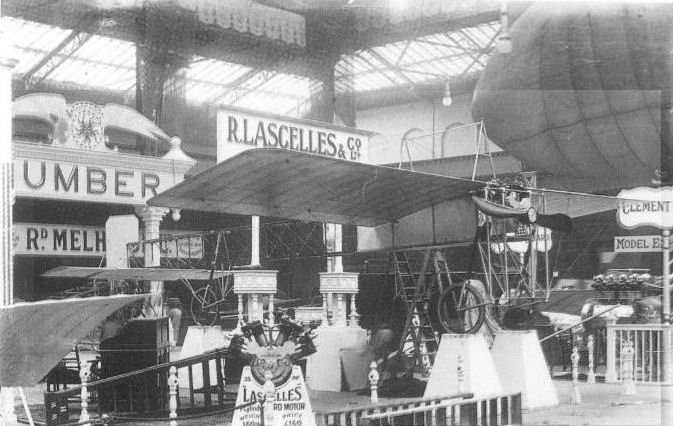
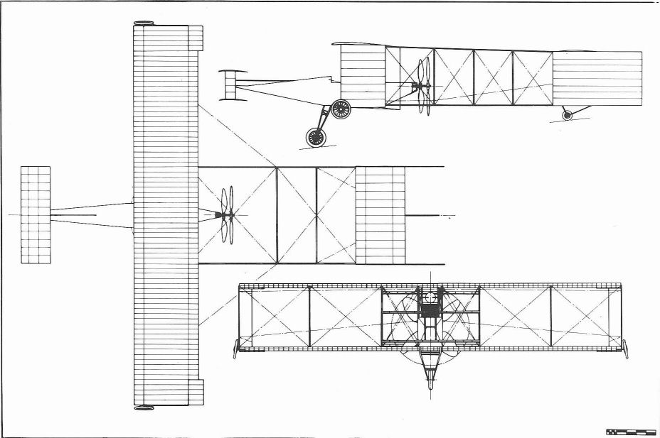
Howard Wright built the 'Ornis' monoplane shown on the Lascelles stand at Olympia in 1910.
OLYMPIA, 1910. - The Ornis monoplane exhibited by Lascelles and Co. resembles the Bleriot type, but is rather larger and somewhat lighter in its construction. It is controlled by an inclined steering-wheel.
OLYMPIA, 1910. - The Ornis monoplane exhibited by Lascelles and Co. resembles the Bleriot type, but is rather larger and somewhat lighter in its construction. It is controlled by an inclined steering-wheel.
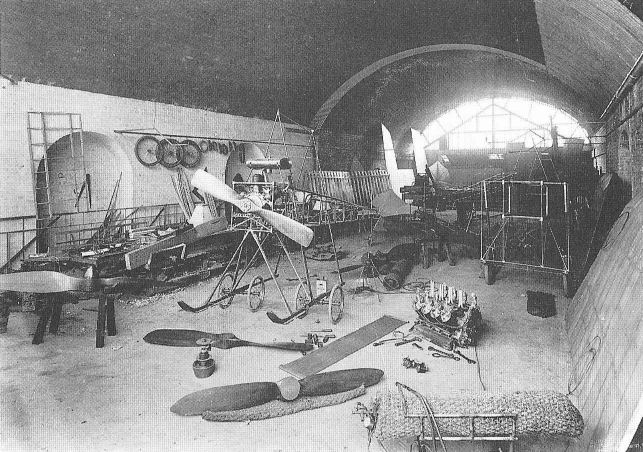
Howard Wright's workshop at Battersea in January 1910. In the foreground is Boyle's Anzani-powered Avis and on the right Lascelles' Ornis under construction
Scottish Aeroplane Syndicate Avis
The Avis Monoplanes were designed by W.O. Manning and built by Howard T. Wright for the Scottish Aeroplane Syndicate of 166 Piccadilly, London, W. Known, as the Golden Plover, the prototype, which was fitted with a 3O hp Anzani engine, was completed at Battersea in December 1909, and delivered to Brooklands for testing. In January 1910, the Hon Alan R. Boyle, who had founded the Syndicate made the initial trials. These did not prove entirely satisfactory and the aircraft was brought back to Battersea to be re-engined with a 35 hp Anzani. A tail unit of decreased area was also fitted. The aircraft, renamed Avis, returned to Brooklands, where Boyle achieved his first straight flights with it in March and April, and his first circular flight in the following month. A little later, he flew the Avis at the 1910 Wolverhampton aviation meeting to win first prize for endurance in the monoplane class with a time in the air of 7 min 53 sec. Early in June, Boyle took delivery of a second aircraft of the type to which he allotted his personal coding, No. 3 being painted on the rudder. Apparently, Boyle regarded his previous machine as having two separate identities. The official nomenclature of Boyle's 'third' aircraft was Avis I and it was fitted with a 40 hp ENV engine. At Brooklands on 14 June, he used his new machine to gain Royal Aero Club Aviator's Certificate No. 13. Almost one month later, at the Bournemouth aviation meeting, Boyle was severely concussed when he crashed in Avis I. In the meantime the prototype Avis had been sold to Maconie. (Unfortunately nothing has been found to identify Mr Maconie or even confirmation of the spelling of his name. There was a statement in The Aero dated 10 August, 1910, which read 'Mr Maconie has put in several days practice on his Avis monoplane, and is rapidly gaining control of the machine.')
Meanwhile, the 40 hp JAP-engined Avis II had been exhibited at the 1910 Olympia Aero Show on the stand of the Aeroplane Supply Co, which acted as selling agents for the Syndicate. After the show it was bought by R.F. Wickham, who had the misfortune, whilst flying it, to experience an engine failure over the sewage farm at Brooklands. Wickham managed to land the aircraft but in doing so struck a raised cement canal crossing the farm. Damage to the machine was extensive. Avis III, also fitted with a 40 hp JAP engine, was purchased by J. Herbert Spottiswode, a well-known racing driver at Brooklands. On 5 October, 1910, Spottiswode piloted Avis III to fifth place in a competition sponsored by the Brooklands Automobile Racing Club, which offered monetary prizes for the greatest aggregate times in the air. N.C. Neill, offered a gold cup, also, to the pilot who flew the longest distance. The event was won outright by Graham Gilmour flying Big Bat with a total time of 2 hr 59 min 16 sec, Spottiswode's aggregate was less than five minutes. Avis III was later purchased by Campbell-Gray, a photographer of 88 Edgware Road, London, who used it for humorous publicity. On recovering from his accident, Boyle returned to flying at Brooklands with the purchase of Avis IV. With the collapse of the Syndicate, however, this aircraft became the subject of the country's first recorded aeronautical auction, held in December 1910, when it was sold, complete with JAP engine, to Eustace Gray, Brooklands' press steward, for ?50.
In appearance the Avis closely resembled many other single-seat monoplanes of the period but the type could be distinguished by its universally-mounted Demoiselle-style tail unit. The fuselage, made of ash, was of conventional wire-braced box-girder construction. The aircraft was controlled by warping the parallel-chord wings from foot pedals, and by the cruciform tail from a control column pivoted at its lower end, the elevator being operated by fore and aft movement of the column and the rudder by turning the wheel attached at the column's upper end. The twin-skid undercarriage was of sturdy construction and each item of it could be replaced without it being totally dismantled. Two pairs of wheels were attached across the skids by rubber cord shock-absorbers and the support for the small tailwheel incorporated a helical spring. The prototype aircraft was fitted with a Chauviere propeller but one made by Howard Wright from a single piece of Kauri pine was fitted together with the more powerful Anzani. All subsequent versions of the Avis had Wright-built propellers.
In flight the Avis was easily controlled and because it had been designed with its centre of gravity well forward, so that there was little or no load on the tail, the take-off was lively, the slipstream from the propeller immediately lifting the tail on starting the engine.
The design was developed further as the 1910 Monoplane.
Avis (as general arrangement)
Span 27 ft; length 27 ft; height 9 ft 2 in; wing chord 6 ft 4 in; wing dihedral 5°; wing incidence 9°; propeller diameter 6 ft 3 in; main undercarriage track 4 ft 6 m; wing area 170.4 sq ft; elevator area 22 sq ft; rudder area 14 sq ft.
Weight without engine 280 lb; weight empty 430 lb; weight loaded 630 lb.
Cruising speed 35 mph; maximum speed 40 mph.
Price ?370-?490.
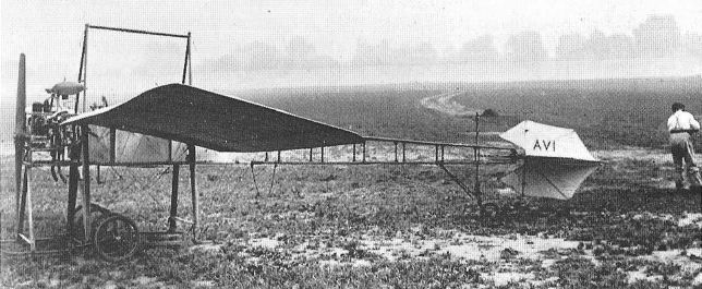
The Hon Alan Boyle's Anzani-powered Avis at Brooklands early in 1910. The authors believe that Boyle regarded this aircraft as his second machine because it had been re-engined with a slightly more powerful Anzani and the tail surfaces had been reduced in area. The photograph suggests that the machine was about to be named Avis, it having previously been known as the Golden Plover.

J. Herbert Spottiswode flying Avis III at Brooklands.
Howard Wright's workshop at Battersea in January 1910. In the foreground is Boyle's Anzani-powered Avis and on the right Lascelles' Ornis under construction
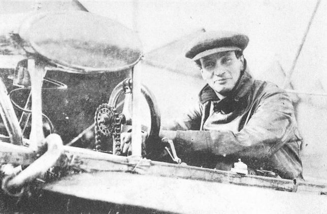
The Hon Alan R. Boyle at the controls of the Avis.
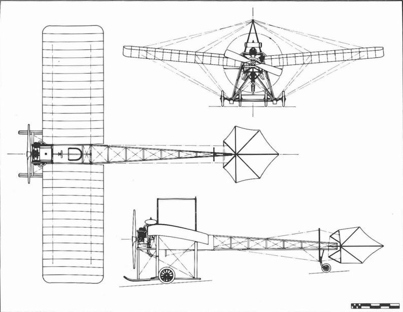
Scottish Aeroplane Syndicate Avis.
Howard Wright 1910 Monoplane
At the 1910 Olympia Aero Show, the stand of Warwick Wright Ltd displayed a new single-seat tractor monoplane, which combined features of the Avis and the earlier 1909 Monoplane. The aircraft also incorporated a number of refinements to reduce drag: the frontal area of the fuselage was kept to a minimum, being dictated solely by the envelope of the 40 hp ENV 'D' engine which had been installed; all fuselage and undercarriage struts were of streamlined section; flat steel ribbons were used for wing bracing; the radiators were mounted full chord at the wing-roots and followed the contour of the wing; and the propeller was given a conical spinner. Otherwise the monoplane was of conventional construction, having fuselage, wings and undercarriage similar to that of the AVIs and a tailplane with end-elevators. A rectangular rudder was fitted, although initial drawings of the monoplane show that it was to have had one of triangular shape. The monoplane, in fact, was the personal property of Warwick Wright and had been built for him by his brother Howard to the design of W.O. Manning, in the month preceding the Show. After the Show, Warwick took the aircraft to the Royal Aero Club's grounds at Eastchurch, where he made the first flight with it on Sunday, 3 April. Soon afterwards, the machine was taken to Brooklands and there Warwick made further flights of increasing duration. On his last flight, however, Warwick swerved to miss some wandering spectators and in doing so ran into a boulder which marked the limit of the sewage farm. The boulder took away the undercarriage but the fuselage and wings continued, depositing themselves and the pilot unhurt in the soft ground of the farm. Apart from the effects on his olfactory sense, Warwick was unshaken by the experience.
Shortly after the appearance of Warwick's machine at Brooklands, another version of the monoplane was flying there piloted by Capt G. Ll. Hinds Howell, an employee of Warwick Wright Ltd. Hinds Howell's aircraft was distinguishable from Warwick's by its full-span elevator and the block radiator mounted below its ENV engine. This monoplane made its first flight on 26 March, 1910. Further good flights were made with the modified monoplane but it met with an accident through a cause similar to Warwick's. On Saturday, 17 September, 1910, the aircraft's wing was damaged in a collision with the propeller of a stationary Weiss monoplane. Hinds Howell, whilst taxi-ing his machine, had swerved to avoid spectators.
In the following month, T.O.M. (later Sir Thomas) Sopwith and another variant of the monoplane made their debut together at Brooklands. The aircraft arrived there from Battersea, on 21 October, and Sopwith spent little time taxi-ing it before attempting a straight flight. After covering some 300 yards in a more or less steady state, he stalled the monoplane on landing and in doing so broke the undercarriage and propeller. The machine was soon repaired. His next attempts, made with more caution, on Friday, 4 November, were rewarded with several straight flights and circuits. Five days later, flights ended with a burst cylinder-head, but on the following Monday, although the weather was bad, Sopwith went up again. Before the month was out, however, Sopwith had sold the monoplane in favour of an Howard Wright 1910 Biplane. In all major respects Sopwith's machine was similar to but slightly larger overall than Hinds Howell's, differing only in having a tailskid instead of a tailwheel and a single cabane strut in place of two wing kingposts.
1910 Monoplanes
Span 27 ft; length 29 ft; wing chord 6 ft 6 in; wing dihedral 2° 23'; wing incidence 9°; tailplane span 12 ft; tailplane chord 3 ft; elevator span each 3 ft; elevator chord 3 ft; rudder height 2 ft 6 in; rudder chord 3 ft; propeller diameter 6 ft; propeller pitch 2 ft 3 in; main undercarriage track 4 ft; wing area 160 sq ft; tailplane area including elevators 36 sq ft; total elevator area 18 sq ft; rudder area 7 sq ft.
Weight without engine 250 lb; weight empty 405 lb; weight loaded 605 lb.
Cruising speed 35 mph.
Price ?630.
Howard Wright Demoiselle-pattern Monoplane
A single-seat single-engine tractor monoplane of Demoiselle-form was under construction in the Battersea workshops of Warwick Wright Ltd during January 1910. The fuselage, at that time, was almost complete and was a wire-braced structure of triangular-section with bamboo longerons and spacers of steel tube. Steel tubing, welded together, was used also to support the 30 hp Darracq two-cylinder water-cooled engine. The main undercarriage wheels were canted inwards, generally following the slope of the fuselage sides, and a small tailwheel was fitted. Construction progressed slowly, owing to work in hand on the Avis machines and Lascelles' Ornis, but by the beginning of the following February, the aircraft's heavily-cambered wings were complete and awaiting their fabric covering. The aircraft was completed in 1910, but no more is known about it.
Span 19 ft; length 21 ft; propeller diameter 6 ft 6 in; wing area 120 sq ft.
Weight loaded 255 lb.
Speed 48 mph.
Howard Wright Monoplane (Enlarged Avis)
A two-seat, enlarged version of the Avis was under construction by Howard Wright in March 1910. The aircraft was to be powered by a 60 hp Green engine, although an ENV engine could be fitted if preferred. This machine was referred to in the technical press of that time as the Antoinette-pattern Monoplane.
Span 42 ft; length 40 ft; total wing area 320 sq ft.
Weight without engine 500 lb.
Howard Wright Bleriot XII-pattern Monoplane
During the summer of 1910, Howard Wright completed a two-seat tractor aeroplane which had some of the features of the Bleriot XII Monoplane. It was powered by a 60 hp ENV engine mounted low in the fuselage. The propeller being driven by a chain. The pilot and passenger, also positioned low m the fuselage immediately aft of the engine, sat with their heads just below or on a level with the wing. The tail unit comprised a monoplane tail with end-elevators and a small trapezoidal-shaped rudder. Although the fuselage was made of wood and acetylene-welded steel-tube, construction of the aircraft generally followed the practice of the period. The undercarriage was the usual arrangement of wheels and skids with a sprung tailwheel.
Span 35 ft; length 46 ft; propeller diameter 8 ft; propeller pitch 3 ft 6 in; total wing area 360 sq ft.
Weight empty 1,100 lb.
Howard Wright Curtiss-pattern Biplane
During the latter part of 1910, Howard Wright completed a single 35 hp-engined pusher biplane on the lines proposed by Glenn Curtiss, of the USA. No drawings or photographs of the aircraft have survived and it must be presumed that Howard's design incorporated the predominant features of a Curtiss biplane of the period, namely mid-gap ailerons and a tricycle undercarriage. In other respects the Curtiss machine resembled the Howard Wright 1910 Biplane.
Span 33 ft; wing area 270 sq ft.
Howard Wright 1910 Biplane
The last and most successful aircraft built by Howard Wright to W.O. Manning's design were the 1910 Biplanes. On many occasions there were likened to and confused with the Farman Biplane but in detail design and workmanship they were incomparable. Further recognition of the attributes of the 1910 Biplane was achieved through the exploits of its pilots, who found it pleasant to fly and tolerant of mishandling.
The aircraft closely followed the pattern for a two-seat pusher biplane introduced by Farman and emulated by many others, with the pilot and passenger seated in tandem in an exposed position over the leading-edge of the lower wing and in front of the engine. Initial versions of the machine were fitted with a 60 hp ENV vee-eight water-cooled engine, its radiators flanking the passenger, but at a later date the aircraft were fitted with a 50 hp Gnome rotary engine. Propellers of Howard Wright manufacture were fitted to all 1910 Biplanes.
The parallel-chord wings were built up on two spars, one spar being positioned along the leading-edge and the other at the aileron hinge line. Both spars were braced along their length with wires passing through the apexes of small sheet-steel inverted-V posts. The upper wing could be increased in area by detachable extensions braced from a kingpost at the leading edge near the joint. Ailerons were mounted on all four wingtips and the extensions when fitted, and were operated from a column placed at the pilot's right-hand side. The pilot's control column was connected, also, to the forward elevator which in turn was linked directly to the tail elevator, and the split rudder was pedal operated. The monoplane tail, built and braced in a similar manner to the wings, could be adjusted on the ground for changes of trim and was carried, like the forward elevator, on four wire-braced booms. The bracing wires in the region of the propeller however, were prevented from flying about, in the event of breaking or coming adrift, by being tied at intervals to cords running parallel with them. The undercarriage was the accepted arrangement of wheels and skids. A large proportion of the airframe was made from Honduras mahogany, ash being used only in the undercarriage and for the rudder post. Fittings were made from cast aluminium and steel and where attachments had to be made the wooden parts were locally reinforced with steel plate. Although production of the biplane was continuous over a period of about a year and each machine was constructed to a common pattern, no two aircraft were identical, modifications being made to suit the customer's individual needs.
The biplane, fitted with upper wing extensions, made its debut at Larkhill, Salisbury Plain, during August 1910, piloted by Lieut E.M. Maitland, who had qualified for his brevet in France. Shortly after taking delivery of the machine, Maitland crashed it at Larkhill. His injuries prevented him making further flights but he had the machine repaired and lent it to his brother officer, Lieut H.E. Watkins, so that he could learn to fly. Watkins took the aircraft to Brooklands and there used it to qualify for his Royal Aero Club Aviator's Certificate, No.25, on 15 November 1910. On his first circuit of Brooklands, Watkins flew with Manning as his passenger. In December, Watkins took the biplane to Shorncliffe, near Folkestone, to compete for the Baron de Forest prize but the aircraft was wrecked before he could start. The biplane had been fitted with an automatic wireless transmitter so that Watkins' flight could be tracked by Maitland from a tug, equipped with a receiver as they crossed the English Channel. After repairs, the biplane was flown on a number of occasions before Maitland sold it to the War Office for ?625 on the opening day of the 1911 Olympia Aero Show. It was officially taken on charge on 23 June, 1911, and given the serial number F3. The aircraft served with No.2 Company, the Air Battalion of the Royal Engineers, at Larkhill, and accumulated 1 hr 56 min flying time before becoming unserviceable on 8 July, 1911. In the following January, it was taken to the Royal Aircraft Factory, Farnborough, and used, ostensibly, in the construction of the B.E.6, serial number 206.
After the sale of Maitland's biplane, Watkins bought another of the same type from John Dones, better known as 'Jack Dare', who was the brother of the then well-known actress sisters, Zena and Phyllis Dare. Dones' biplane was the second to be built and was delivered to him at Eastchurch at the end of September 1910. This aircraft was also owned at a later date by W.D. Johnstone.
The third 1910 Biplane brought the type into prominence through the exploits of its pilot, T.O.M. Sopwith. Sopwith's machine arrived at Brooklands in November 1910, from Eastchurch. The morning of 21 November saw Sopwith attempting a few straight flights without having taken any instructions on handling, and in the afternoon he made a number of circular flights, which included three to qualify for Aviator's Certificate No.31. Three days later, and with only ten hours flying to his credit he entered the biplane for the British Empire Michelin Cup competition for the longest nonstop flight by a British pilot in a British machine. Sopwith's flight from 10.15 am to 1.18 pm covering 107 miles not only set up new British records but also put him in a strong position to win the prize. The next two weeks were spent in modifying the ENV-powered standard pattern biplane for longer flights. The modifications included: adding upper wingtip extensions with ailerons; fitting a large-capacity petrol tank in place of the passenger's seat; the addition of a fabric-covered fairing for the pilot's protection; and repositioning the control column to between the pilot's legs. On 18 December, the Baron de Forest prize was Sopwith's with a flight of 169 miles in 3 1/2 hr from Eastchurch to Beaumont in Belgium. Sopwith's biplane also gained the distinction of being the first all-British aircraft to be flown across the English Channel. As 1910 drew to a close Sopwith set out to improve his time for the Michelin Cup and on 31 December, the last day of the contest, established a new record of 4 hr 7 min 17 sec with a flight of 150 miles 246 yards. However, the prize was not to be his, S.F. Cody claimed it at the last moment with a flight of 195 miles in 4 hr 50 min.
On 1 February, 1911, Sopwith flew his biplane to Windsor Castle at the invitation of HM King George V, a journey made from Brooklands in thick mist and intense cold. In April, the biplane was displayed on the Royal Aero Club's stand at the Olympia Aero Show before being taken by Sopwith in the following month, to the USA. Sopwith's tour of the USA proved extremely successful, many passenger-carrying, demonstration and stunt flights being made interspersed with competitive flying. The tour, however was not without mishap, the biplane being wrecked on two occasions; at Columbus, Ohio, on 3 June, when Sopwith skimmed low over a field and the starboard undercarriage skid dug into a small hillock, and near Manhattan Beach, on 10 September, when the engine failed and Sopwith and his passenger came down in the sea. The biplane was repaired after both accidents! On his return from the USA, Sopwith established a school of flying at Brooklands and used the biplane for training, for which role it had been fitted with dual control in March 1912.
The next ENV-powered biplane was exported unassembled to New Zealand in 1910. It had been bought by two Auckland brothers, Leo and Vivian Walsh with the backing of an enthusiastic syndicate. They, with the aid of their sisters, completed the biplane late in 1910 and, after initial tests during which Vivian Walsh had to teach himself to fly, the biplane was given its first public demonstration before New Zealand's prime minister at Papakura on 5 February, 1911. About a year later, the biplane was taken over by W.S. Miller and F.E. Sandford, who rebuilt and modified it to have sweptback outer-wing panels and a semi-enclosed cockpit. The biplane was tested in its new form at Avondale Racecourse, Auckland, in February 1913. It subsequently made a number of successful flights but was finally written-off after a crash at Alexandra Park, Auckland, on 6 December, 1913. The only other biplane, fitted with an ENV engine, known to have been flown abroad was that owned by W. C. England at Rangoon during the summer of 1912.
At home, the 1911 Olympia Aero Show heralded a new variant of the biplane. Although it followed the original pattern, the layout was adaptable for racing for which purpose it had been built for Robert Loraine, the Irish actor who had achieved fame with his crossing of the Irish Sea in the previous September. The biplane was powered by the 50 hp Gnome rotary engine salvaged after the crossing from Loraine's Farman racing biplane, and it was the first time that this type of engine had been used in any Howard Wright machine. To adapt the aircraft for racing the lower wings could be reduced in span by removing their outer sections. This was accomplished simply by releasing ten bracing wires, undoing two bolts and removing two struts from their sockets at each wingtip. Alterations to the controls were avoided by the fitting of broad-chord ailerons only to the upper wing. The only other noticeable difference a minor one, was the fitting of undercarriage skids which had their forward portions more upturned than usual. After the Show the aircraft was flown at Brooklands.
The second Gnome-powered biplane, also a racing pattern was bought by Claude Grahame-White, who flew it during the latter part of 1911 at Hendon. During 1912 Grahame-White used the biplane for training at his newly established flying school and at which, on 6 June, no less than six pilots used it to qualify for their aviator's certificate, among them No.231 awarded to Marcus Dyce Manton, who was later to become chief test pilot and inspector to the English Electric Co. The others were: H.C. Biard, F.H. Fowler, T.O'B. Hubbard, R.T. Gates and Lieut B.T. Janes. Two weeks later N.S. Roupell and E.H. Morriss gained their brevets. The last to qualify on the biplane was R.H. Kershaw on 16 July. In the meantime Grahame-White had married Dorothy Taylor, whom he had met in New York. On this occasion the biplane was flown by the bridegroom to the reception held at Sir Daniel Gooch s mansion, Hylands, at Widford in Hertfordshire. Seven days later, on 6 July, the biplane was flown by Lewis Turner to win the speed handicap race at Hendon. In July, also, Turner crashed the biplane at Harlow, Middlesex.
The last two biplanes to be built were entered for the ?10,000 Daily Mail Circuit of Britain race and the second Michelin Cup competition respectively. The former machine was fitted with upper wing extensions, a small bluff fairing in front of the pilot and 60 hp Green engine. It was flown by Lieut H.R.P. Reynolds who, although delayed by previous competitors for the race, made a good start in the evening of Saturday, 22 July, 1911. Reynolds landed at Hendon that night. He spent Sunday adjusting the engine to give more power and making several circuits to test its performance. On Monday he rejoined the race, reaching Doncaster by nightfall. Reynolds arrived at Harrogate the next day but there was forced to retire from the race. J.L. Longstaffe, the pilot of the other machine fared little better, his attempts at the Michelin Cup being thwarted by mechanical trouble.
Records show that Capt G. Ll. Hinds Howell and one Louis de Silva also piloted the biplane at Brooklands during 1910. Production of the biplane, however, ceased with the sale of Howard Wright's aircraft interests to the Coventry Ordnance Works.
1910 Biplane (Standard pattern)
Span 36 ft; span upper wing with extensions 48 ft; length 36 ft 6 in; height without wing extensions 12 ft; wing chord 6 ft 6 in; gap 6 ft 6 in; aileron span 6 ft 6 in; extension aileron span 6 ft; aileron chord 1 ft 6 in; forward elevator span 8 ft 6 in; forward elevator chord 3 ft; tailplane span 12 ft; tailplane chord including elevator 5 ft 6 in; elevator span 12 ft; elevator chord 1 ft 6 in; rudder height each 2 ft 6 in; rudder chord each 3 ft; propeller diameter 8 ft; propeller pitch 4 ft 8 in; wing area including ailerons 454 sq ft; wing area with extensions including ailerons 532 sq ft; total aileron area 39 sq ft; total aileron area with extensions 57 sq ft; forward elevator area 25.5 sq ft; tailplane area including elevator 66 sq ft; elevator area 18.5 sq ft; total rudder area 15 sq ft.
Weight empty 800 lb; weight loaded 1,200 lb.
Maximum speed 45 mph; cruising speed 36 mph; endurance 5 hr.
Price ?1,000.
1910 Biplane (Racing pattern)
Span upper wing 36 ft; span lower wing 22 ft; length 37 ft; wing chord 6 ft; gap 6 ft.
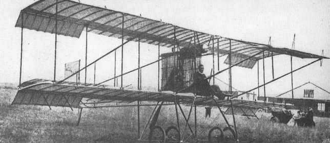
'Jack Dare' with his Howard Wright 1910 Biplane, the second built, at Eastchurch in October 1910.
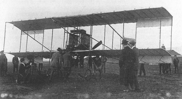
Lieut Maitland's and Lieut Watkin's Howard Wright 1910 Biplane on the occasion of being handed over to the Air Battalion of the Royal Engineers.
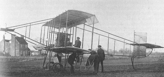
T. O. M. Sopwith's Howard Wright 1910 Biplane undergoing repairs to an aileron at Brooklands.
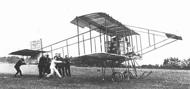
Howard Wright 1910 Biplane bought and assembled by the Walsh brothers at Auckland New Zealand, in 1911.

T. O. M. Sopwith seated at the controls of his modified Howard Wright Biplane with which he won the #4,000 Baron de Forest prize for the longest flight into Europe.
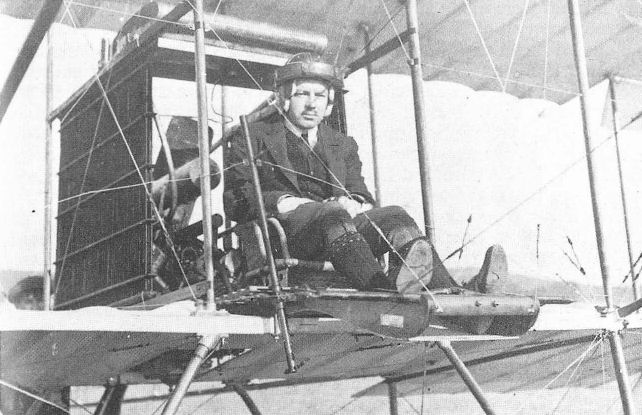
Lieut H. E. Watkins.
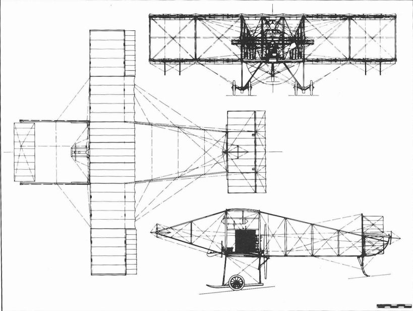
Howard Wright 1910 Biplane (Sopwith's Aircraft).
Howard Wright-Capone Helicopters
Among the first of Howard T. Wright's commissions was a helicopter, the product of the remarkably inventive mind of Federico Capone, whose work has remained relatively unknown because of his own modesty and horror of publicity. This helicopter was Capone's second design. His first was the result of some thirty years spent in research to solve the problem of flight for which aim he had built in succession a series of models, several of them ingenious but quite complicated. In 1905, he achieved moderate success with his first full-scale experiment, when he, with the aid of his mechanic, Ceccarelli, constructed a form of pilotless helicopter. The main structure of the aircraft was built of steel tubing, as were the two rotors which were covered with aluminium sheet. The rotors were coupled and driven by a motor-cycle engine developing 4 1/2 hp, and rotating cams were used to vary the incidence of the rotor blades to reproduce the helicoidal motion of rowing oars. The whole machine weighed only 240 lb. Capone proposed to launch the helicopter from a scaffold tower, erected in a field near the Coliseum in Rome, and to cushion its fall with a stretched cable. On 30 April, 1905, all was ready for the initial launch when a violent squall upset the aircraft, damaging the rotors. The trials were recommenced a little later and made at Altavilla Irpina, in the province of Naples, where the helicopter was launched from a high terrace and achieved sustained flight for a short distance. Having proved the rotor principle capable of practical application, Capone concluded that it would be necessary to pilot the aircraft to keep it in the air for any length of time and flying in the required direction. A modified form of this helicopter was granted British patent 28,590/1907.
In 1907, Capone moved to Arpaise in the province of Benevento and there designed a second helicopter based on his earlier experiments. Unlike the first its construction was undertaken by Howard Wright. Detailed drawings for the helicopter were completed at Howard's office at Belgravia Chambers during the winter of 1907-08 and shortly afterwards the aircraft took shape at the Marylebone workshops of Warwick Wright Ltd and subsequently at those at Battersea. The helicopter was built of thin-walled steel tubing, supplied by Accles & Pollock Ltd of Birmingham, welded together without the aid of sockets, to form a central box-shaped structure carrying two cantilever frameworks. The upper surface of the framework was extended in area by the addition of a steel tube lattice with balloon-cord leading and trailing edges, and the whole covered with fabric to provide flight surfaces. The rotors, their axes inclined outwards from the vertical, were mounted at the cantilevers' extremities and driven through a system of shafts and spur and bevel gears by a single 50 hp Antoinette water-cooled engine, mounted transversely within the central structure. Two paddle-shaped blades were fitted to each rotor, the pitch of which was varied by means of a cam such that the blades had incidence only when travelling rearwards. The main undercarriage comprised four rubber-tyred wheels, whilst six smaller wheels were used to prevent the helicopter toppling over on landing. The rear starboard main undercarriage wheel was driven by a chain from the rotor drive shaft to enable the helicopter to be taxied. Directional control and stability of the machine were achieved with a system of movable surfaces: a large tailplane hinged at the trailing edge of the main surface; two triangular rudders, built on wooden frames, hinged at the corners of the tailplane and two triangular surfaces beneath the rotors, which provided roll control and propped the aircraft on the ground. The control surfaces were cable-operated from three small winches placed within easy reach of the pilot who sat cradled within the central structure aft of the engine. Another somewhat curious control device was fitted: it consisted of two large rectangular surfaces, mounted adjacent to the main framework, driven by the engine through a gear train, an eccentric and a slide. The resultant flapping motion, according to Capone, created 'billowy-like air currents beneath the body of the apparatus to increase its stability.'
The flight of the helicopter, as envisaged by Capone, would have provided an interesting, if not alarming, spectacle. The rotors were to lift the aircraft to a reasonable height at which altitude the speed of the rotors would be reduced, and, because the machine's centre of gravity was well ahead of its centre of lift, the aircraft would glide forward. The extent of the flight surfaces was such that at 20 mph the helicopter was expected to support its own weight. After a certain interval and before the machine had reached the ground, the rotor speed would be increased to lift it once more into the air. By intermittently increasing and decreasing the speed, the aircraft would proceed in a series of curves or billows.
In March 1908, the completed helicopter was conveyed to the privacy of a large tent, erected at one corner of Norbury Golf Links, which were situated southwest of London on the road to Croydon. On Friday, 7 March, Howard Wright and his assistants wheeled the machine from its hangar and proceeded to test it in secrecy. The initial trials, which involved taxi-ing and tethered hovering manoeuvres, revealed a number of defects. Contemporary reports of these tests and the accompanying descriptions of the helicopter fail to mention two small-diameter, four-blade tractor propellers geared to the rotor drive-shaft. The propellers are clearly visible in photographs (unsuitable for publication), of the helicopter at Norbury, and were shown on the drawing accompanying British patent 7,129 granted to Capone in 1908. Possibly, propellers were added in the intervening days before the helicopter's second series of tests in an attempt to provide forward movement. However, all of the tests proved unsuccessful, inasmuch as the machine failed to lift its pilot and only when its all-up weight of 1,250 lb had been reduced to 650 lb did it rise readily to two feet clear of the ground, a restriction imposed on the helicopter by its tethers. Clearly, the power of the engine and the size of the rotors were inadequate, although the rotors were considered to be particularly efficient, giving a lift of 33 lb/hp at the rotor axis, with the blades set at a maximum incidence of 37 degrees and rotating at approximately 100 rpm.
To achieve success, Capone was faced with several solutions by which he could improve the helicopter's performance: the main ones of which were to reduce substantially the all-up weight; increase the motive power or to improve the efficiency of the rotors. Capone took the last course of action by designing rotors of larger diameter, but also decided to design a new machine. Again, Howard Wright was asked to undertake its construction. Meanwhile, the helicopter at Norbury was dismantled for delivery to Capone in Italy.
In the course of designing the third helicopter a considerable weight saving was achieved and the need to install a more powerful engine, if one had been available, was less acute. The redesigned helicopter, according to the short-lived magazine The Airship, was fitted with a single 30 hp REP, seven-cylinder air-cooled semi-radial engine, and the weight of the aircraft, including the pilot, was 600 lb. The magazine continued: 'The fans are each 26 ft in diameter and run at 90 to 100 rev/min. The soaring speed is only about fifteen miles per hour, and as the old fans lifted 650 lb there should be plenty of power with the fans of the new machine, which are 6 ft larger in diameter. The motor is cooled by a large fan, which acts as a propeller. It weighs 130 lb complete in running order, with magneto, carburettor, pipes, oil and all fittings. The framework of the aeroplane is entirely of steel tubes welded together without sockets. It weighs but 120 lb, which is decidedly light in view of the fact that the main plane is 30 ft wide, 22 ft deep. The reduction gear, which transmits 30 hp and gives a reduction of 10 to 1, weighs 12 1/2 lb. The 30 hp clutch weighs but 15 lb. Perhaps, however, the fans are most remarkable in this respect. Each of them only weighing 40 lb, including the hub. The blades are 6 ft 6 in long and 3 ft wide. The main plane is mounted on three strong motor-cycle wheels, with spring forks on the two in front, which are 20 ft apart.' In all other respects the third helicopter was similar to the second.
The fact that The Airship was able to give a detailed specification in November 1908, when the article was published, indicates that the design or construction of the third helicopter was very advanced and must have been started soon after the trials of its predecessor. On 9 January, 1909, Flight recorded: 'Howard Wright helicopter now completed and sent to Italy, tests in England were eminently satisfactory.' Much later, on 30 October. 1909, with Howard Wright in attendance, the helicopter was tested on the military parade ground at Naples. Of the trials La Stampa reported them successful and a French source stated: 'The inventor not having risked sitting in the machine to pilot it, the launch was made simply on the inclined plane which had been prepared to this end.'
Nothing further was heard of the helicopters but they were not to be Capone's last efforts in the field of moving wing aircraft, for it has been recorded that Howard Wright built for him an ornithopter and another helicopter. Details of the former remain unknown. Work on the fourth helicopter was started in June 1909 and was completed that year.
Helicopter No.2
Span across tips of rotors 48 ft 2 in; overall length with rotors fore and aft 27 ft; rotor centres and wing span 28 ft 10 in; rotor diameter 19 ft 4 in; rotor blade length 6 ft 4 m;. rotor blade maximum chord 2 ft 4 in; wing root chord 11 ft 8 m; tailplane span 13 ft 2 in; tailplane chord 8 ft 2 in; propeller 'diameter 4 ft 8 in; propeller centres 10 ft; undercarriage wheel base 6 ft; undercarriage wheel track 4 ft; wing area 160 sq ft; tailplane area including rudders 81 sq ft.
Weight loaded 1,250 lb.
Gliding speed 20 mph.
Helicopter No.3
Span across tips of rotors 56 ft; rotor centres and wing span 30 ft; rotor diameter 26 ft; rotor blade length 6 ft 6 in; rotor blade maximum chord 3 ft; undercarriage wheel track 20 ft.
Weight 600 lb.
Gliding speed 15 mph.
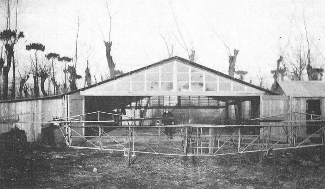
The second Howard Wright-built Capone helicopter at Naples in 1909.

The first Howard Wright-built Capone helicopter under construction at Marylebone.

Howard Wright's drawing for Capone's helicopter patent application, 7,129 of 1908.
Moore-Brabazon Powered Glider
Inspired by the gliding of Archdeacon and Farman, J.T.C. Moore-Brabazon decided, on his return from France in the early autumn of 1907, to put his own ideas into practice. Armed with sketches for a glider with wings of about 25 ft span and a heavily cambered section, he asked the Short brothers, Oswald and Eustace, to undertake its construction. For ?25 they produced a well-built aircraft of ash and bamboo with varnished balloon fabric covering the wings. They also took the opportunity to modify the original design, the result being that it appeared with a larger span and almost flat wings. The glider was controlled by a forward elevator mounted on triangulated outriggers, and drag-plate rudders attached to the outermost rear interplane struts. Landing skids and four jettisonable wheels comprised the undercarriage. On completion at the Short's Battersea works, the glider was taken to Brooklands and there housed in a shed alongside that of AV. Roe's.
A few tests were made with the glider, but it was soon decided to fit a 24 hp eight-cylinder Buchet engine. In May 1908, Moore-Brabazon asked Howard Wright to make the required alterations for the engine. By the time Howard had completed his task at Brooklands, very little of the original glider was recognisable, although the 35 ft span wings were used without structural change. The modified aircraft retained the forward elevator, now carried on outriggers level with the lower wings, but was fitted with a fixed tail level with the upper wing. The engine drove a small-diameter pusher propeller with four paddle-shaped aluminium blades. The undercarriage, redesigned to have four castor-action wheels, was to prove the design's undoing for it was found to be weak and unsteady. The inadequate power of the engine also did not contribute to its success. Consequently, the biplane was not tested to any degree but remodified and flown as a kite by Moore-Brabazon at Chelmsford in Essex.
The Phoenix P.1 was not the company's first aircraft project. The first was a twin-rotor helicopter observation platform designed by Pybus and embodied in patent 109,672 applied for on 30 September, 1916. The contra-rotating rotors were directly coupled to squirrel cage induction motors with aluminium windings, mounted at the extremities of a box-girder structure, which carried the observer and his parachute. Power for the motors was supplied from a ground or ship-based generator by an electric aluminium cable that served also as a tether. Pybus sought in the smallness of the device a means of reducing the vulnerability of observation platforms, then carried aloft by large unwieldy balloons and kites.

Phoenix helicopter observation platform.
P.1 Twin-float two-seat pusher seaplane powered by one 200 hp Sunbeam engine. Four bombs were carried vertically inside a streamlined fairing below the crew nacelle.
Bomb load 400 lb. Span 67 ft 9 in; length 34 ft; wing area 825 sq ft. Weight loaded 4,220 lb. Maximum speed 69 mph; climb to 6,500 ft, 30 min.
Bomb load 400 lb. Span 67 ft 9 in; length 34 ft; wing area 825 sq ft. Weight loaded 4,220 lb. Maximum speed 69 mph; climb to 6,500 ft, 30 min.
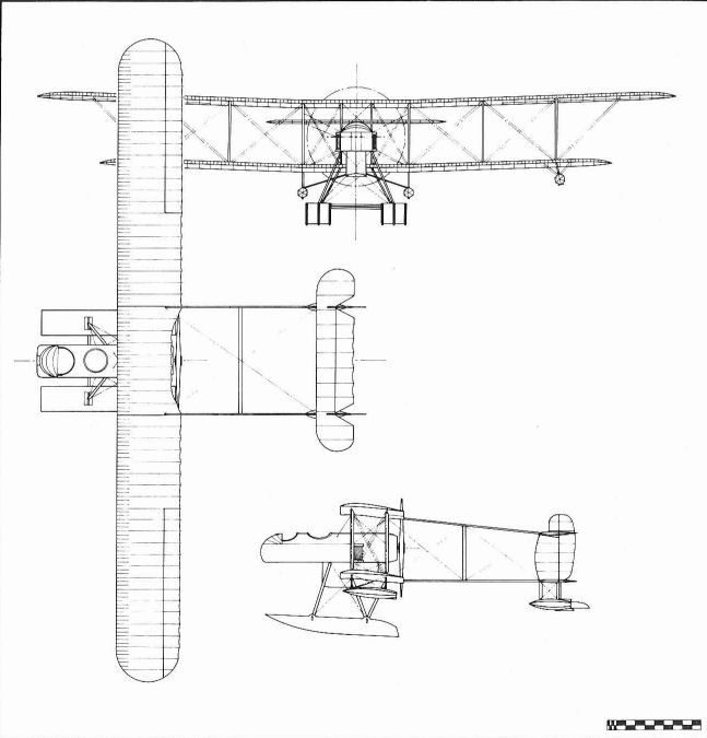
Phoenix P.1.
P.2
This project number was given to two machines. Both designs were prepared to specification N.2b under an Admiralty contract signed in 1917. The machines were allocated serial numbers N22 and N23. Each machine had a crew of two and was powered by one 200 hp Hispano-Suiza engine. Armament consisted of one fixed Vickers gun for the pilot and a Lewis gun for the observer. Three 65 lb bombs were carried.
The first design was a tractor type which had a two-tier fuselage. The upper part carried the engine and tail unit and was attached to the lower hull by extensions of the centre-section interplane struts. Span 42 ft 3 in; length 33 ft; height 11 ft 6 in; wing area 510 sq ft. Weight loaded 3,315 lb. Maximum speed 91 mph; climb to 10,000 ft, 28 min.
The second design was a twin-float pusher seaplane.
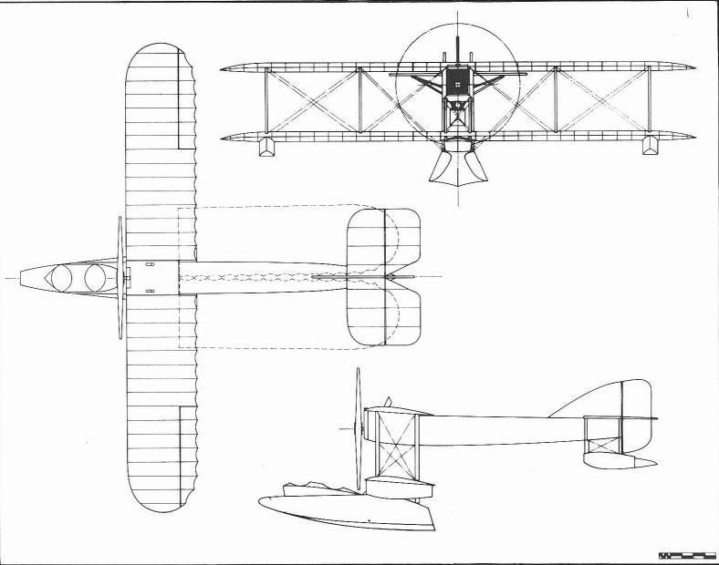
Phoenix P.2.
P.3
Twin-float two-seat tractor seaplane designed to specification N.2b and closely resembling Short Type 184. Powered by one 350 hp Rolls-Royce Eagle engine. Span 56 ft 10 in; wing area 765 sq ft. Weight loaded 5,350 lb. Maximum speed 98 mph; climb to 6,000 ft, 15 min.
Twin-float two-seat tractor seaplane designed to specification N.2b and closely resembling Short Type 184. Powered by one 350 hp Rolls-Royce Eagle engine. Span 56 ft 10 in; wing area 765 sq ft. Weight loaded 5,350 lb. Maximum speed 98 mph; climb to 6,000 ft, 15 min.

Phoenix P.3.
Phoenix P.5 Cork
On 31 October, 1917, a memorandum, signed by F.E.T. Hewlett on behalf of the Controller, Technical Department (TIN Section), was sent to Maj John Buchanan, Controller of the Air Board's Technical Department. The memorandum requested the Air Board's approval for a contract to be placed with the Phoenix Dynamo Manufacturing Co Ltd, of Bradford, for the design and construction of the aero-structure of two experimental F.3 flying-boats, whose hulls were then being built at May, Harden & May Ltd's Kingston Bridge Works at Hampton Wick on the River Thames. Approval was given under British Requisition No.256 and Sir William Weir, Controller of Aeronautical Supplies, was notified of the Board's decision on 12 November. Three days later, Phoenix was instructed to proceed not only with the design of the aero-structure but also with preparations for the production of the complete aircraft. Drawings of the hulls were forwarded and Phoenix was particularly requested to:
'1) Increase the aerodynamic efficiency of the present machine [the standard F.3], keeping the wing roots exactly the same as the present machine in order that the aerial structure should be interchangeable with standard design.
2) Simplify the design of the machine in order to facilitate production.'
The contract, No. AS 37016/17, was signed on 28 November and the two flying-boats were allocated serial numbers N86 and N87. Phoenix gave the flying-boats the designation P.5, the appellation Cork not being used until about June 1918 after the issue of Technical Department Instruction 538 (later to become AP 547) regarding aircraft nomenclature. The Cork came in the category of aircraft with more than one engine and of 11,000-20,000 lb all-up weight to be named after seaboard towns in Scotland and Ireland.
The P.5 was the result of an Admiralty decision to build a large twin-engine flying-boat to meet specification N.3B (later known as RAF Spec XXX), which the Admiralty's Air Department had formulated early in 1917, for an anti-submarine patrol machine of similar displacement to the Porte-designed Felixstowe flying-boats. The Admiralty decided also that the P.5 should have a hull designed by Lt Cdr Linton C. Hope, and authorised May, Harden & May to build two hulls to his principle of monocoque construction. This type of structure proved to be remarkably strong, yet resilient, and enabled the hull to have good streamline form. Generally, the Linton Hope hull was covered by two thin layers of narrow planks, the inner layer usually being wrapped diagonally and the outer laid longitudinally, rivetted to closely-pitched hoops attached to numerous stringers, which were in turn fastened to almost circular hoop frames, the whole being built up on a keel that ran from stem to stern. The planning bottom was added separately and was similarly constructed.
Manufacture of the hulls, which were not identical, started towards the end of 1917. The first hull appears to have been completed shortly before 11 April, 1918, when Maj A.J. Miley, Assistant Controller, Technical Department (Design), informed Phoenix of the measured weight and position of the centre of gravity of the hull, and the second a little later. The first could be distinguished from the second by its planing surface, which, although discontinuous at the main step, extended aft to the rear step: the second hull had only a forward planing bottom and small rear step faired to the basic hull, the chine-line of the rear step being formed by a strake that was continuous with the top of the fin deck of the forward surface. (In R & M No.461: The Resistance of Flying Boat Hulls, published in July 1918, the first hull was numbered P.5 and the second, P.5A. This nomenclature was also used, though not widely, by Phoenix who applied the designations to N86 and N87 respectively. The order in which the hulls were eventually to be used however, was reversed, the P.5 hull being fitted to N87 and vice versa). The basic structure of both hulls was identical and each had openings in the upper surface for the bow gunner, pilot and copilot, who were seated in tandem, and the engineer. There were also two gunners' waist-hatches closed by detachable doors which had glazed portholes, although Linton Hope had, at one stage, considered a single cockpit on top of the hull for the rear gunner. Holes were also provided in the top-sides of each hull for the spars of the lower-wing centre-section. The hull's covering consisted of two layers of mahogany planks separated by a layer of varnished fabric for water proofing. The outer planks were laid longitudinally and were 5/32 in thick and the inner were wrapped diagonally and were 5/16 in thick, the whole being rivetted with copper nails and roves to 3/8 in square spruce timbers or hoops spaced 1 3/4 in apart. These had their ends let into the rock elm keel and were glued to 35 stringers of 1 1/2 by 1/2 in spruce, distributed evenly around the periphery of the hull and attached to almost circular frames placed at intervals of 2-3 ft. The frames were fastened directly to the top of the keel and were steam-bent from a length of rectangular-sectioned rock elm, joints being scarfed and made alternately at the top and bottom of the hull. The lower part of the hull was reinforced by short transverse strips of square-sectioned spruce, known as floors, which passed through the keel. Each hull's forward planing bottom had two mahogany skins separated by varnished fabric, the inner diagonal planking being 3/32 in thick and the outer 3/16 in, and fastened to a structure similar to that of the basic hull but with plywood transverse bulkheads, which created a number of watertight compartments. The rear planing bottom of the first hull was built in a similar manner, the thickness of its inner and outer planking being 5/64 in and 5/32 in respectively. That fitted to the second hull was little more than a fairing to the rear step but was also of Linton Hope construction.
The first hull was delivered by road from Hampton Wick to Bradford before the end of April 1918, and was followed soon afterwards by the second, its journey northwards beginning on Wednesday, 8 May. Total production time for the two hulls was recorded as 31,348 man-hours.
Meanwhile, on 9 April, May, Harden & May had delivered models of the hulls, which they had made to contract No. 38A/167/C.160 at a cost of ?26-8-0 each, to the Technical Department, where they were received by Linton Hope himself. These models were then made over to the NPL and used for comparative wind-tunnel tests, the results obtained being published in R & M No.461. The tests revealed that the first or P.5 hull had considerably less drag at all speeds than the second or P.5A hull. A modified P.5 hull, in which the fin deck was faired to the basic hull by a concave fillet, was also tested. It too was found to have less drag than the P.5A and was even marginally better than the original form. Despite the P.5's superiority, which would have been reflected in the performance of the complete flying-boat, it was stored on arrival at Bradford and the P.5A hull used in its place. The reason for this change remains obscure but possibly it had its origin as early as November 1916, when R & M No.300: Experiments with Models of Seaplane Floats, Eleventh Series was published. This report gave details of hydrodynamic tests conducted at the NPL on a model hull, similar to the P.5, supplied by Linton Hope. Various alterations were made to the hull and the form which was finally evolved was similar to the P.5A. This hull had better seaworthiness characteristics in that side waves created by the forward planing bottom finished as fan-shaped sprays clear of the stern. Previously, heavy spray was thrown up well above the top of the hull by the forward surface and the side waves tended to curl in and over the rear portion of the hull, with consequent saturation of and damage to wings and tail surfaces if they were set too low. It would appear that the P.5 hull was passed over in favour of the P.5A because of the former's poor seaworthiness. That the P.5 hull was built suggests that comparative full-scale trials were to be performed.
At Bradford, in the spring of 1918, the aero-structure, which had been designed by W.O. Manning, was nearing completion. Its design had been done under the supervision of the Technical Department, which had checked and approved Manning's calculations and had made recommendations where necessary. An instance of this had occurred on 11 March, 1918, when Solly Brandt of the Structures & Stability Section had reported to Cdr Alec Ogilvie, Controller, Technical Department (Design), on the strength of wing spars, interplane-struts and bracing-wires, which, with the exception of a few control wires considered under strength, were found satisfactory. In accordance with Phoenix policy, that had resulted in the book Women on munitions of war being written by P.J. Pybus, Phoenix's managing director, at the instigation of the Prime Minister Lloyd George, all parts of the flight structure were designed to enable female labour to be used wherever possible. This policy was applied to the manufacture of wood and metal components. Of the latter fabricated items were reduced to a minimum, others were designed with mass-production in mind, and, in general, fittings and bolt sizes were standardised so that most parts were readily interchangeable and the variety of stores could be kept to a minimum.
The unequal-span wings were made in sections: the upper wing in three, of which the outboard were braced from faired kingposts above the outermost interplane-struts, and the lower in four, of which two formed the lower centre-section, since on N86 the spars passed through the hull. Although a similar arrangement had been envisaged for N87, this section was built in one piece and attached directly to the top of the hull, the joint incorporating a streamline fairing. Each wing section had two box-spars made entirely of spruce and consisted of booms separated by distance pieces and webs joined to them by glue and screws. To reduce wastage the webs could be made from a number of short lengths spliced together, the number of splices, however, was strictly controlled. Ribs of RAF 14 aerofoil section were, in general, of Warren-girder construction and built from strips of spruce but those at the wing joints were fret-sawn from plywood and were lightened by elongated holes cut in them. Three-ply birch was used to cover the lower-wing leading-edge, to protect it from spray damage, and also the lower centre-section walkway used mainly by the engineer to start and tend the engines. Internal wing-bracing was by means of wires and tubular-steel struts, the ends of the latter being located solely by sockets in the spar fittings. Interplane and engine-struts were made of thin-walled steel tubes which had their ends sweated into and rivetted to socket attachments and which were faired by a fabric-covered wooden framework with three-ply leading edge. Reinforcing pieces of walnut or mahogany were fitted to the spars in way of connections for all struts and external bracing-wires, which were also of streamline section. Both wings were covered with fabric laid diagonally in broad strips and stitched to the ribs in the normal manner. Ailerons were fitted to the upper-wing only: each aileron was made in two parts to cater for wing deflections and was hinged to a secondary spar placed at a short distance behind the rear spars. The wingtip floats of N86 were identical to those fitted to the Felixstowe F.3; N87's were a little deeper.
The tailplane was of similar construction to the wings but had an inverted RAF 15 aerofoil section and was made in two parts joined on the centre-line each half being braced to the hull by four faired tubular-steel struts. Three-ply was used instead of spruce for the spars' webs otherwise the materials used were the same as for the wings. Tailplane incidence could be varied on the ground by relocating the two bolts that joined the rear spar and passed through the rudder post. A horn-balanced rudder of composite wood and steel tube construction and of characteristic shape was fitted. The fin was readily detachable for covering and transport, having a diagonal box-spar which passed through the hull top and was joined to the keel by one bolt.
Two 360 hp Rolls-Royce Eagle VIIIs were specified for and installed in each flying-boat, the engine mountings being similar to those used on the Felixstowe machines. Both engines were fully enclosed in cowlings made of flat wooden-backed aluminium panels. Three main fuel tanks were situated beneath the centre-section: the forward and transverse tank contained 80 Imp gal of petrol and the others 120 Imp gal each. All tanks were of the same diameter, and baffles, sumps and pipe connections were made alike. Two wind-driven Rotoplunge pumps delivered the petrol to two 20 Imp gal gravity tanks carried below the upper centre-section. The petrol system was duplicated so that either or both engines could be run from either gravity tank. The engine throttle control was the subject of British patent No.122,996 filed by Manning on 17 July, 1918. It consisted of a single lever connected by short cranks to two pulleys around which were wrapped the control wires to the engines. When the lever was pushed straight forward both throttles opened simultaneously and if it was moved to the right, the port engine was given more throttle than the starboard and vice versa.
The basic armament of both flying-boats was four 230 lb or two 520 lb bombs carried below the lower wing roots and five Lewis guns, one at the bows on a Scarff ring, one each for pilot and co-pilot on either side of their cockpits on rail mountings, and one on a gallows mounting at each waist hatch. N87 had in addition two small nacelles fitted to the trailing-edge of the upper wing, each equipped with one Scarff ring-mounted Lewis gun and to which the gunners gained access by climbing the steps on the innermost rear interplane-struts. In August 1918, Phoenix were asked to study the possibility of carrying 520 lb bombs sunk into the hull end of the lower wing in the event that the bomb load as planned came too near the water. Comments were also requested as to how four 520 lb bombs could be carried. These proposals came to nothing, however.
On 5 July, 1918, the Technical Department was notified of the completion of N86 and was asked for permission to erect the flying-boat at Brough, on the Humber Estuary. Exactly one week later another letter was sent stating that 'the P.5 [would be] ready for despatch very shortly'. Permission was given the following day and soon afterwards N86 was taken by road to Brough. Some parts, including the tail unit various struts and engine cowlings, were delivered by rail, however. These were sent on 26 and 27 July. Before N86's completion, Phoenix had asked that Clifford B. Prodger be allowed to pilot the machine on its initial trials, to which the Technical Department had consented on 4 July with the proviso that Maj M.E.A. Wright would undertake subsequent test flights.
The first flight of N86, designated Cork Mk I, was made on Sunday, 4 August, 1918, between 6.24 and 6.33 pm by Prodger with Lt Cdr Hume observer, and Capt Slater, engineer, both of whom represented the Admiralty. Two more flights were made before 8 o'clock that day, one of 8 minutes and the other of 28 minutes. All took place in fine weather with a Force 1 northeasterly, wind blowing. Prodger reported that performance was very satisfactory. He thought, however, that N86 was slightly nose heavy and that the rudder was too small. On account of the latter he did not attempt to fly at maximum speed. After the trials N86 was moored overnight on the mud of the estuary foreshore and brought in at 5.30 the following morning. Between then and the next test flight made on the evening of 9 August, the covering of N86's wings was found to have stretched slightly but this factor apparently made little difference to the test as it was reported to be a 'fine performance'. A new and enlarged rudder had been fitted for this flight which lasted 54 minutes and was made with N86 fully loaded. Prodger was again at the controls and his crew comprised Hume, Slater and Finch, an engineer from Rolls-Royce. The test was witnessed by Maj Maurice Wright and Maj Miley who were to be pilot and passenger respectively for the allocation flight to be made the following morning. This test began at 11 :08 after some difficulty in starting the engines and was of 12 minutes duration. Because of the engine trouble another flight was arranged for the afternoon but it again proved to be a lengthy process starting the engines. By 4 o'clock, however, everything was in order but the tide was low. Nevertheless, a decision was made to proceed with the test. Unfortunately, just as N86 reached planing speed she struck a rock and started sinking, eventually grounding when half full of water. The crew worked hard to restart the engines, which had stalled soon after the accident, succeeded in doing so, and were able to taxi the flying-boat shorewards to ground her on the mud. By that time it was 7.30 pm. Salvage operations could not be undertaken next day because Phoenix-built F.3 N4416 was launched and test flown leaving no time to attend to N86. The following morning, however, the hull was patched and the machine brought ashore. After repairs, N86 was flown by Maj Wright to the Marine Aircraft Experimental Station, Isle of Grain, on 24 August, 1918.
N86 passed final AID inspection at Grain the following day and during the ensuing week was test flown to obtain preliminary information of handling, climbing and speed, which was officially reported in NM 219, dated 31 August, 1918. Among the structural defects noted in the report was the slackness of the wing covering. Criticisms were made of the cockpit layout with regards to seats, instruments and throttle control, which was not considered as good as two separate levers capable of being grasped by one hand, this form being more familiar and natural to pilots. The criticisms, however, appear unjustified since, shortly after the hulls were delivered to Bradford, the cockpits were mocked-up using one of the hulls and their arrangement officially approved. The report continued: 'The machine is light on the lateral control and there appears to be sufficient [control]. It comes off a bank well. The rudder might be a little larger with slightly more balance and a higher gearing. The elevator is fairly light and effective. The machine is a little nose heavy. The boat is very stable in getting off and landing, no tendency to porpoise being noticed. A fair amount of water is thrown on the propellers when taxi-ing, and the bombs are washed by water thrown up by the fin (the outermost surface of the forward planing bottom), but not by a solid wave....The machine was taken off and landed in a slight lop. Apart from spray on the propellers the get-off was good, and the landing was very soft and free from. shocks'.
An investigation into the cause of the slackness of the wing covering revealed that the type of dope used was unsuitable. As N87 was then under construction and its wings had been treated with a different dope, a decision was made to use them to replace those of N86. The exchange was effected in October 1918 and the original wings were sent back to Bradford for recovering and fitting to N87.
It was evident from the preliminary trials that the wings of N86 were set too low on the hull. This fact almost certainly led to the wings of N87 being mounted on top of the hull (the holes in the hull for the spars were plugged).
Trials with N86 were resumed in October after the new wings had been fitted. On 17 October, Grain Test Report NM 219B was published giving comparisons between N86 and the Felixstowe F.5 prototype, N90, of the view from the pilots' cockpits, layout of instruments, crew accommodation, handling, and take-off and landing performance. With the exception of instrument arrangement and crew accommodation, which were regarded as inferior in the Cork, there was little to choose between the P.5 and F.5. The author of the report might have mentioned (although in fairness to him he was probably not asked to record) that the P.5 was superior to the F.5 under the same operational conditions, in speed, climb and range, and in ability to carry a heavier payload. The report also noted that the P.5 had not yet been tried in rough seas and that the main step had given way once, possibly owing to its being strained on the machine's launching trolley. There followed another report, No. NF 2346, dated 22 October, concerning the rudder of N86 and this apparently led to the fitting of one on the lines recommended in NM 219. Overload trials were conducted and reported in NM 240b dated 10 May, 1920. At a later date N86 was fitted with navigation lights.
N86 was thereafter used experimentally at Grain and was known to have been flying as late as April 1924, when it was the subject of impact tests described in R & M No.926.
Construction and assembly of N87, which became known as the Cork Mk II, started about the end of August 1918. On 24 September, Phoenix were notified by the Technical Department of major alterations to be made to the hull. Fortunately by that time only the uncovered lower centresection and fin had been fitted (whether they had to be dismantled to allow the hull to be modified remains unknown). The alterations were made to Air Board drawing No. D.S.3.034: P.5 proposed production hull lines and were done at Bradford by May, Harden & May's boat-builders between 15 October and 2 November. The hull then resembled that fitted to N86 but had its rear step placed farther aft.
From then, N87's assembly proceeded steadily and by 25 November the uncowered centre-section minus engines and the complete tail unit had been installed. However, further delay occurred when it was discovered that the wings would have to be recovered as the wrong type of dope had been supplied and used to treat them. The Cork Mk II was eventually delivered by road to Brough on 21 February, 1919, for final erection.
N87's first flight took place during the late afternoon of Friday, 28 March, and lasted 7 minutes only, being curtailed because of strong winds. The crew comprised Majors Miley and Wright, pilots, CPO Dryden, Shanate of Rolls-Royce, West of Phoenix and Edwards, engineer. Gales and rough seas foiled attempts, in which a tailplane stay-tube was damaged, to bring N87 ashore and she was left moored to a buoy until the following Sunday evening when it was found that she had not shipped water. The Cork was observed to ride out the gales well and this fact was subsequently widely publicised by Phoenix, who compared N87 to its namesake. Despite the bad weather conditions the test was successful: the take-off was automatic, handling and stability, according to Maj Wright, was perfect, and N87 climbed strongly at 80 mph against a 25 mph head wind. Criticism was made, however, of the petrol pumps and cocks, the former for not delivering fuel at a sufficient rate, and the latter for being dangerously placed between the chain connecting the pump and its windmill. Recommendations were made concerning serviceability, in particular, for a towing-eye positioned at the stern for the connection of a rope, to minimise damage to the tailplane stay-tubes by manhandling. Undoubtedly, more test flights were made although these appear to have been interrupted when the wings were recovered yet again, Phoenix receiving a contract, No.PB35A/166/C.66, dated 24 May, 1919, for this work. N87 was flown by Maj Wright to the Isle of Grain in June and from then was used experimentally.
In December 1919 the planing bottom of N87 was badly damaged when the machine was brought ashore on its trolley in rough weather. Repairs were made and completed early in 1920. One result of this accident was the invention of a trolley using inflatable water bags to cushion the hull.
During the summer of 1922 a decision was made to install two 450 hp Napier Lions in N87. A trial erection of the engines, which were uncowled and mounted on a revised arrangement of struts, was made at Bradford. Afterwards, the engines and structure were delivered to the Isle of Grain and fitted to N87, which was then redesignated Cork Mk III. The first flight of N87 with its new engines lasted 10 minutes and was made by Flt Lt G.E. Livock on 2 August, 1922, the day it was to have joined the Flying-Boat Development Flight at the start of its cruise from Grain to the Scilly Isles. N87's flight had been delayed by a faulty petrol system. Flt Lt (later Group-Captain, DFC, AFC, RAF) Livock recalled the occasion saying: 'We had a rather 'do-it-yourself' system, constructed, I think at Grain and not by the makers, and fuel poured into the hull instead of the engines when we turned on the petrol. We had to do quite a bit of pumping out and mopping up before the flight'. N87 Joined the Development Flight cruise off Spithead on 4 August.
The primary object of the cruise was to gain experience of operating flying-boats away from their home station using a ship as a base. The unit consisted of Short N.3 Cromarty N120, one standard Felixstowe F.5, N4038, one F.5 with Lion engines, N4839, and N87, accompanied by HMS Ark Royal, the parent ship, HMS Tintagel, a destroyer, and the RAF Floating Dock towed by HMS St Martin, a tug. Pilots assigned to the flying-boats were Flt Lt B.C.H. Cross, Flg Off Carey, Flg Off E.P. Davis and Flt Lt G.E. Livock respectively, and the Development Flight was commanded by Sqn Ldr R.B. Maycock. The final report and recommendations of the Flight were given to the Commanding Officer, Marine & Armament Experimental Establishment (Home), Isle of Grain, by Sqn Ldr Maycock on 31 October, 1922. The report began by stating the objects of the cruise in detail and listing the equipment and personnel involved. It continued:
'Summary narrative of the cruise.
Sheerness. The experimental flying boats were handed over to the flight on 13 July, 1922, and, with the assistance of a party of men loaned from M & AEE (H), the programme of work which it was considered essential to carry out to render them fit for the cruise, was completed, as far as possible by 31 July, 1922.
All the flying boats, with the exception of P.5, which was only completed on the day of departure, were tested and found satisfactory before departing.
The Ark Royal arrived off Grain on 25 July, 1922, and commenced taking in stores and petrol.
Spithead. With the exception of N.3, which was left behind at the last moment to change an engine, the Unit sailed for Spithead and assembled there on 4 August, anchoring about 3 1/2 miles SW of Calshot.
The Unit remained here for four days during which refueling experiments with the Ark Royal plant were carried out. This, at first gave trouble as a considerable quantity of water was found to be present in the petrol tank, the presence whereof has, so far, remained unexplained.
N.3, N120, joined the Unit on 7 August, having had a new Condor engine fitted at Grain.
Portland. The anchorage at Portland was very safe and no amount of wind at this base would have affected the security of the aircraft. It was, however, very congested and considerable judgement was necessary in handling the flying boats when coming up to and leaving the moorings.
A considerable amount of engine trouble was experienced here with the Napier Lions installed in F.5, N4839, and Rolls-Royce Condors in N.3, N120, and minor hull and rigging defects were corrected in all flying boats. It was not possible, therefore, to carry out many concerted tests at this port and, moreover, it was considered by the Officer Commanding Unit that it was only on passage to its main base at Plymouth prior to leaving for the scene of operations and that it was not the intention to carry out trials at this stage. The weather at Portland was alternately good and bad.
Plymouth. The Unit assembled at Plymouth on 14 August, 1922, and anchored in.
A programme of exercises and tests was prepared, but little of this programme was actually carried out owing to a recurrence of engine failures and administrative difficulties arising out of the 'serious differences' reported by the Captain to have arisen between himself and the senior RAF Officer. Up to this period, however, a great deal of useful information and data had been collected on the general scheme of working with a Parent Ship, the maintenance and handling of flying boats as a unit, on the water, moorings, refuelling, and the inestimable value of the Seaplane Dock.
The weather at Plymouth was similar to that experienced at Portland, wet and fine days alternating, and the effect of this was beginning to show up on the flying boats. Rust and corrosion could not be kept under and the planes were becoming groggy.
Scillies. The Unit sailed for and arrived at St Mary's Roads, Scilly Isles, on 21 August, 1922. This anchorage possesses practically no shelter from the SW except for a few rocks, and the Atlantic swell very rarely, at this time of the year, ceases to roll in from that direction and, if accompanied by any wind, the sea becomes dangerous to any craft of small tonnage. In this respect this anchorage proved the most severe test of the seaworthiness of the flying boats of almost any possible to select.
The south westerly swell was so continuous that it was found impossible to use the Seaplane Dock on more than an average of one day in four, owing to its excessive movement and the wash and send of the sea inside when submerged for docking.
On days suitable for air operations, it was, generally speaking, quite calm, and the swell at the anchorage coupled with the fact that there was no wind, made the difficulty of getting the flying boats off into the air one of some hazard, and imposed a great strain on the hulls and superstructure....
[The] Scillies is the most exciting testing place but, when working there, the best anchorage should be selected. This, however, was not done, as, in the first instance, the flying boats were moored out to sea and windward of the Parent Ship and the Destroyer. Later, they were moved to a more sheltered position but not until they had rode out one gale during which it was impossible to get them in and, to illustrate this, it may be mentioned that the ships' boats were hoisted or sent to St Mary's for shelter.
At this base the maintenance of hulls and superstructure absorbed all the energies of the Flight and as it was not always possible to use the Dock, repairs were executed on a sandy beach and the pool off this beach provided the best anchorage for flying boats.
The period spent at the Scilly Isles was the most instructive of the whole cruise from an experimental point of view and, although the numbers of hours flown was negligible compared with what could have been carried out had the flying boats been of a standard type, the experience gained in the proving and establishment of certain definite characteristics of flying boats - both affecting their possibilities and limitations - should prove of assistance in determining their future military value and to designers in evolving a seakeeping aircraft.
[On 31 August, 1922, Flt Lt Livock made an aerial reconnaissance of Falmouth in conjunction with N4038, during which take-off tests were conducted in Mount's Bay and N87 was refuelled from HMS Tintagel off Penzance.]
Eighteen days were spent at the Scillies and the weather prevailing was similar to that usually experienced during November. The flying boats had become so saturated and engines so corroded with salt water - due partially to their age, partially to the exposed anchorage and partially to the constant bad weather - that it was deemed advisable as a result of these conditions coupled with the loss of N.3, N120, from the same causes, to move the base back to Portland.
Portland. The Unit sailed for and assembled at Portland on 8 September. N.3, N120, having been lost at the Scillies and N87 having sustained serious damage to the forward step during the flight to Portland, only the two F.5 types remained effective and with these, two successful air operations were carried out from this base, also some further experimental trials.
On the completion of these operations and trials the Unit was prepared for the return flight to the Home Base at Grain, and, on 18 September 1922, the Unit sailed.
Grain. The two F.5s reached Grain without incident but P.5, N87, came down at Newhaven, the outer aluminium exhaust manifold on the port engine having fallen off in the air and remained suspended by a wire stay.
The Ark Royal arrived at the Nore on 19 September and came up harbour on the following day and, by 09.00 hours next day, all RAF personnel and stores were landed as the vessel was required for service elsewhere. '
The report proceeded to give more detailed accounts of the performance of each flying-boat and the rest of the unit. Comparisons of the types were made and it was concluded that N87 was better than the Cromarty and far superior to either of the F.5s. The conclusion took into consideration each machine's condition at the start of the cruise and that of N87 was rated the worst! Appended to the report were the comments of the pilots on the performance and defects of their machines. Those of Flt Lt Livock read:
General characteristics. No figures were taken for performance except take off which averaged 24 secs in a flat calm with no wind and full load up.
The air speed indicator did not work correctly so it is difficult to gauge the exact full speed which is somewhere in the region of 101-104 mph.... The best cruising speed was about 78 mph, the leading speed [sic] being about the same as on F.5.
Control. The controllability in the air is excellent with the exception of the aileron control which appears to be a little insufficient, this is noticeable at very low speeds such as stall landings and take offs.
The rudder and elevator controls are very good.
This type is much more pleasant to fly for long periods than the F.5, and is not nearly so tiring on the pilot.
There is a very pronounced 'snatching' on the elevator controls when engine speeds are varied in the air. This may be due to the tail oscillation [caused by lateral bending of the hull].
Control on water. The machine is very steerable on the water at low speeds, but sea anchors are required for picking up moorings etc, except in very strong winds, as the machine travels very fast through the water even with the engines throttled right down.
The controllability at high speeds such as when taking off is good and the tendency to porpoise can be controlled to a great extent by the elevator.
The difficulty in taking off is the danger of dipping a wing tip into the water. The wing tip floats being so low, any tendency of the machine to roll laterally has to be quickly checked, otherwise damage to the wing tip can easily result. This makes a cross wind take off especially difficult. When taxying across a cross wind at any speed it is quite easy to entirely submerge a wing tip float and have water running 'green' over the lower plane. Apart from this the machine is very clean when taxying, not making nearly so much fuss as on F.5.
Seaworthiness. The seaworthiness of this machine was well tried out as six gales were ridden out without any damage whatever, and high seas, especially at the Scillies, were frequently experienced. It is interesting to note that one gale of Force 6, lasting nearly 24 hours was ridden out safely without the rear side doors in place. A small amount of water was taken in but not enough to endanger the machine. A certain amount of water, however, is taken in at these doors when taxying side to wind or turning quickly on the water.
Loss of performance. The loss of performance, both in the air and taking off, as well as controllability was very marked towards the end of the cruise, this I consider due to the following causes:-
(1) Hull becoming sodden with water.
(2) Considerable leaking into the outer skin, which could not be kept under by the bilge pump.
(3) Fabric on planes becoming slack. It is pointed out that the fabric was old and practically rotten before the cruise started.
(4) Planes becoming out of truth from various causes.
To sum up it is considered that this type [P.5] with the few small alterations recommended in this report should prove infinitely superior to the present F.5 in almost all respects.'
Group-Capt Livock later recounted the last days of N87. 'The last flight [from Portland on 18 September, 1922] was very unpleasant. I just managed to haul her off the water after taxying for miles. In the air she was horrible on account of the enormous load of water carried in the step compartment. Off Newhaven, I had to force land owing to an exhaust manifold breaking off and directing the exhaust flames on to the magneto. I attempted to take off again after effecting temporary repairs but owing to her poor condition and having regard for the bumps felt from the crests of the waves this seemed inadvisable, so I taxied her into Newhaven harbor and tied up to a mooring in the entrance. That night a gale sprang up, the mooring dragged or parted and N87 crashed into a pier. The machine was then towed up the harbour to a jetty where we secured her. Whilst attempting to dismantle her on the water, she heeled over, filled up and sank. We eventually hauled her out of the water in pieces, which were put on a trailer and taken back to Grain by road.'
Interest in the Cork was shown in many quarters, particularly by the American Aviation Mission in August 1918, and by Boulton & Paul Ltd who received drawings of the hull in December 1919 to study for its conversion to steel and wood construction.
A civil variant of the Cork, designated P.8, was considered by the Phoenix Dynamo Co. It was to carry ten passengers or freight. Manning also investigated the possibility of entering the Cork for the ?10,000 prize offered by the Daily Mail for the first direct transatlantic flight. His calculations indicate that the Cork could have accomplished the flight with ease.
The Cork was later developed as the Napier Lion-powered English Electric P.5 Kingston.
Span: upper 85 ft 6 in, lower 63 ft 6 in; length: Mk I 48 ft 7 3/16 in, Mk II and III 49 ft 1 11/16 in; height: Mk I 20 ft, Mk II and III 21 ft 2 in; length of hull 45 ft; hull width across chines 7 ft 6 in; hull maximum depth 6 ft 2 in; wing chord 9 ft; wing incidence 40; wing dihedral: upper 3 (outboard section only), lower 0; gap at inboard interplane-struts 10 ft; stagger nil; aileron span 19 ft 11 1/2 in; aileron chord 2 ft 1 in; tailplane span 25 ft; tailplane chord including elevator 8 ft 6 1/2 in; tailplane normal incidence 5 30'; elevator span 25 ft; elevator chord 2 ft 9 m; fin height 6 ft 3 m; fin root chord 10ft 1 in; rudder height Mk II and III 10 ft 3 5/8 in; rudder chord Mk II and III 4 ft 0 1/8 in; propeller diameter 10 ft; wing area including ailerons: Mk I 1,292 sq ft, Mk II and III 1,340,5 sq ft; total aileron area 85,5 sq ft; tailplane area including elevator 200 sq ft; total elevator area 58 sq ft; fin area 31 sq ft; rudder area: Mk I (9 Aug, 1918) 22.5 sq ft, Mk II and III 42 sq ft; total stabiliser area 34.5 sq ft.
Hull weight: P.5 1,417 lb, P.5A 1,306 lb; empty weight: Mk I 7,350 lb; loaded weight: Mk I 11,600 lb.
Maximum speed: Mk I 105 mph at sea level; climb to 5,000 ft: Mk I 10 min; service ceiling: Mk I 13,000 ft; endurance: Mk I 8 hr.
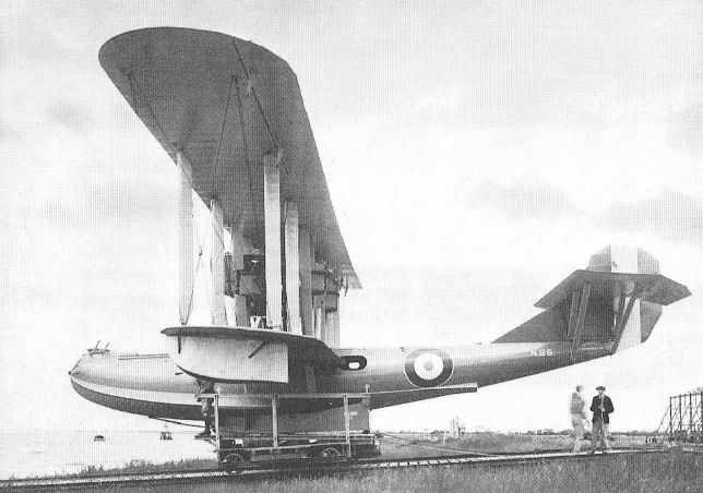
Cork Mk I N86 on the slipway at Brough.
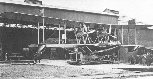
The Phoenix Cork N86 on the apron outside the hangar at Brough on the Humber Estuary, August 1918.
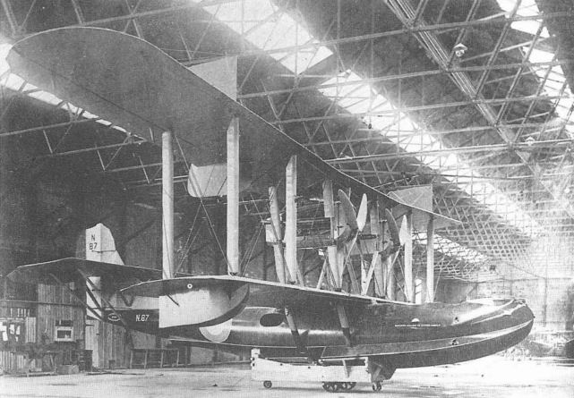
Cork Mk II N87 inside the hangar at Brough.
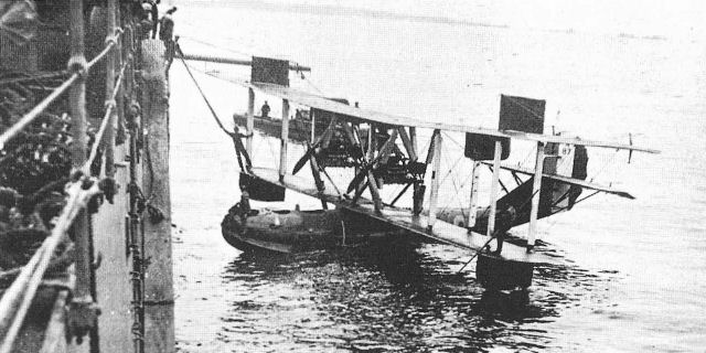
Cork Mk III N87 drawing alongside HMS Ark Royal during the cruise to the Scilly Isles.
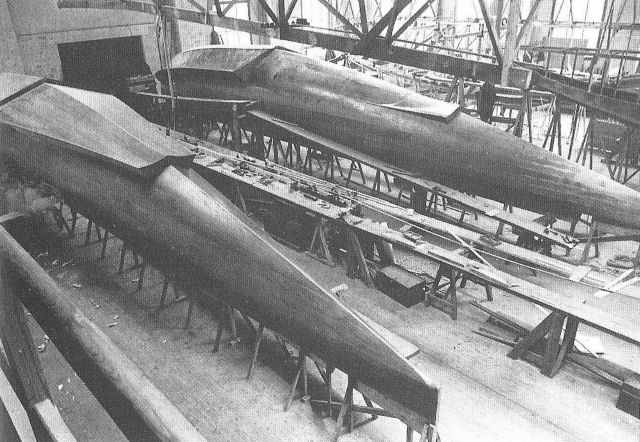
P.5 (foreground) and P.5A hulls under construction at May, Harden & May's Kingston Bridge Works.
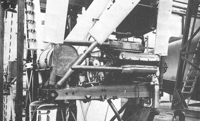
Part of the Napier Lion engine installation intended for the Cork Mk III. The nose of the hull of the Fairey Atalanta II is just visible in the background.

Phoenix P.5 Cork Mk II.
P.4
Two-seat pusher flying-boat with Linton Hope hull powered by one 275 hp Sunbeam Maori engine. Originally designed to specification N.2b, it was modified in 1919 to take three or four seats, and under the name Grey Mullet was suggested as a suitable aircraft for the private owner. Armament: one Lewis gun, four 100 lb bombs. Span 55 ft 11 in; length folded 41 ft; wing area 660 sq ft. Weight loaded 4,630 lb. Maximum speed 95 mph; climb to 6,000 ft, 22 min; endurance 4 hr.
Two-seat pusher flying-boat with Linton Hope hull powered by one 275 hp Sunbeam Maori engine. Originally designed to specification N.2b, it was modified in 1919 to take three or four seats, and under the name Grey Mullet was suggested as a suitable aircraft for the private owner. Armament: one Lewis gun, four 100 lb bombs. Span 55 ft 11 in; length folded 41 ft; wing area 660 sq ft. Weight loaded 4,630 lb. Maximum speed 95 mph; climb to 6,000 ft, 22 min; endurance 4 hr.
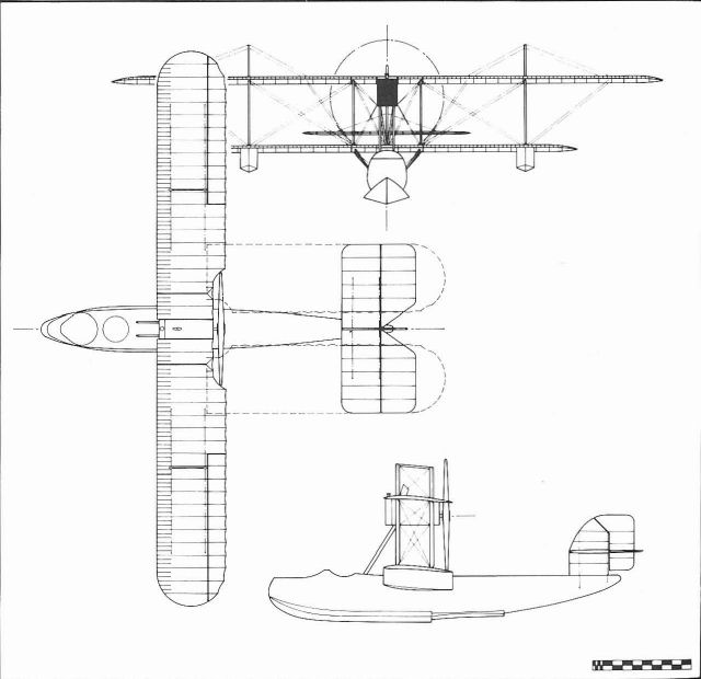
Phoenix P.4/English Electric Grey Mullet.
P.6
Pulex. Anti-submarine patrol flying-boat powered by six 600 hp Rolls-Royce Condor engines mounted in tandem pairs and driving tractor and pusher propellers. Six crew. Bi-, tri-, quadru- and quintoplane arrangements were considered but the first was adopted for the final design, together with a biplane tail unit having a large central fin and twin outboard rudders. The hull was to be of Linton Hope construction. Armament envisaged: twin Lewis guns at bow and upper wing nacelles and six 500 lb bombs carried below the lower wing-root. In 1919 the Pulex was offered for civil use, in which role it was intended that it carry 40 passengers or 11,200 lb of freight. Span 201 ft 6 in; length 88 ft 9 in; height 44 ft 6 in; wing area 7,077 sq ft. Weight loaded 65,000 lb. Cruising speed 100 mph at sea level; climb to 6,000 ft, 26 min; range 800 miles; endurance 8 hr at cruising speed. January 1918.
P.7
Eclectic. Long-range civil flying-boat possibly designed to a specification issued by the Royal Mail Steam Packet Co. The Eclectic was intended to carry 50 passengers each with a luggage allowance of 50 lb, or 14,650 lb of freight. Passengers were allowed ample room to move about in luxuriously fitted cabins, which included dining and smoking rooms, the latter being of fireproof construction and built on top of the hull. Sleeping births were also provided for use on long journeys. The flying-boat was powered by eight 600 hp Rolls-Royce Condor engines geared together in two groups of four, each group driving one tractor propeller of 25 ft diameter. Some experimental work was conducted and included the design of steel spars and an investigation into the use of steam turbine-driven propellers. Span 248 ft 6 in; length 103 ft 6 in; height 51 ft 6 in; wing area 10,000 sq ft. Weight loaded 100,000 lb. Cruising speed 80 mph; range 1,600 miles; endurance 20 hr at cruising speed. December 1918.
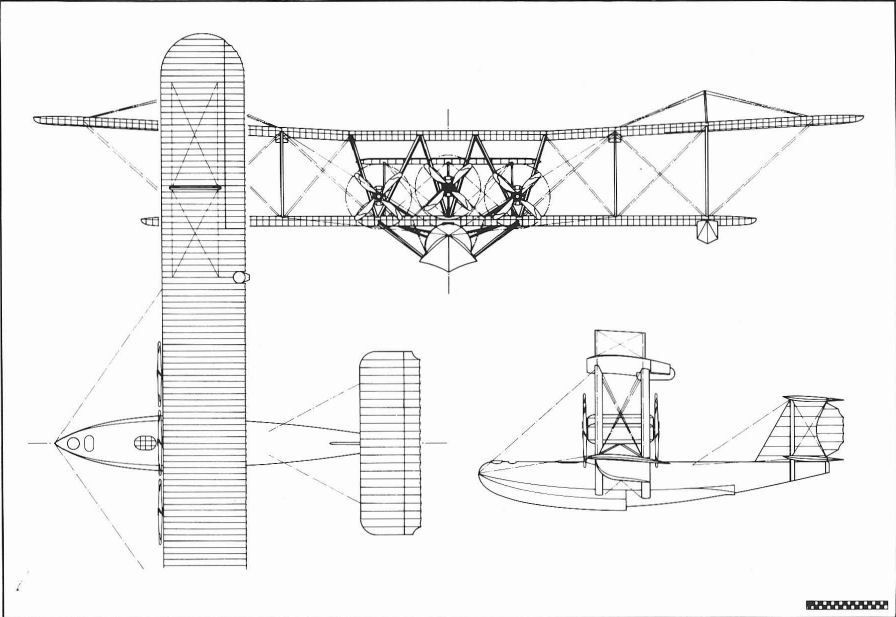
Phoenix P.6 Pulex.
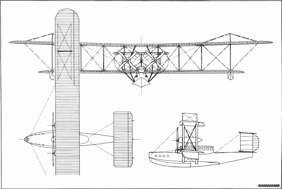
Phoenix P.7 / English Electric Eclectic.
Poynter Monoplane
During May 1910, Howard Wright built a single-seat tractor monoplane designed by E.J. Poynter, a well-known artist who lived near Brooklands. The monoplane was of sound design and bore the hall-marks of Wright's first class workmanship. It followed conventional construction of the period but was readily distinguishable by its large Demoiselle-style tail and tapered wings. Power was provided by a 60 hp Green engine driving a two-blade propeller. Construction was undertaken at Battersea and tests were made at Brooklands in June but the aircraft was never flown, because Poynter was injured in a car accident.
Span 45 ft; length 28 ft; wing root chord 9 ft; wingtip chord 6 ft; wing area 320 sq ft; elevator area 60 sq ft; rudder area 30 sq ft.
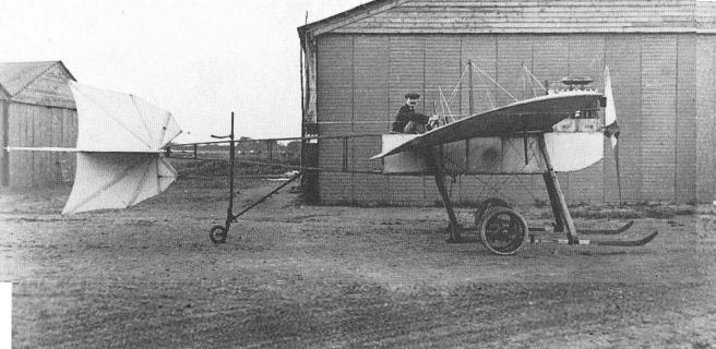
Poynter had his monoplane built by Howard Wright in 1910. It was taken to Brooklands but never flown owing to an accident to the owner.
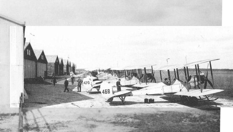
CENTRAL FLYING SCHOOL, UPAVON. - A view of the machines of A, B and C Flights from the rear, with the B.Es. of A Flight nearest the camera.
Line-up of BE2 early variants at the Central Flying School at Upavon in July, 1914 (note that '416 is a BE6). The type proved to be not only a useful operational aeroplane but also a very effective trainer type. B.E.2a, 468, was built by the Coventry Ordnance Works.
Line-up of BE2 early variants at the Central Flying School at Upavon in July, 1914 (note that '416 is a BE6). The type proved to be not only a useful operational aeroplane but also a very effective trainer type. B.E.2a, 468, was built by the Coventry Ordnance Works.
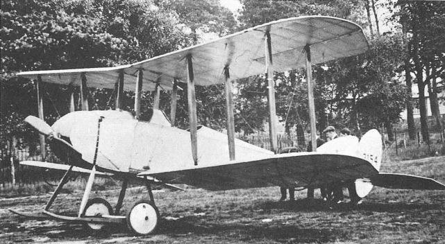
COW-built B.E.8a 2154 at Farnborough, early in 1915.
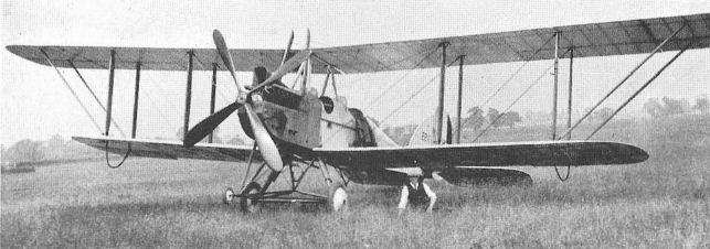
COW-built R.E.7 2213.
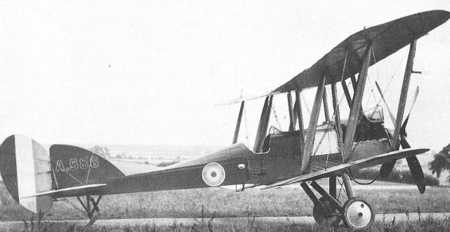
COW-built B.E.12 A586.

Production of B.E.12as at the Coventry Ordnance Works.

COW-built R.E.8 B6644 presented to the Royal Flying Corps by A.G.L. of Stoke Pages.
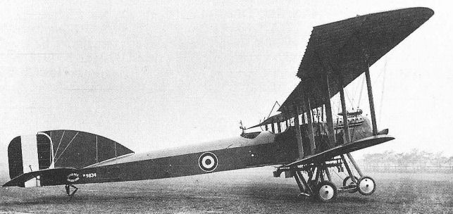
First Phoenix-built Short Bomber, 9834, was tested by Clifford Prodger on 3 August, 1916.
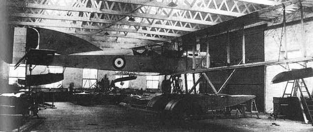
The first Phoenix-built Short Type 184, 8368, being assembled at Bradford in January 1916.
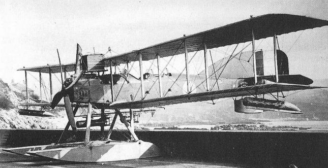
Phoenix-built Improved 184 N1754 with 260 hp Maori I engine at Cattewater in 1918.

COW-built Sopwith Snipe E6544 which served postwar with No.17 Squadron.
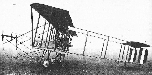
Phoenix-built Maurice Farman Longhorn N5333 photographed on Sunday, 7 January, 1917. It was dismantled the next day and despatched to RNAS Eastchurch on the followmg Tuesday.
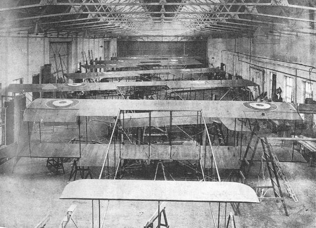
Maurice Farman Longhorn production at Bredford, January 1917.
Derived from the F.K.9, the F.K.10 was ordered into production, but only eight were built owing to contract cancellations.