
Книги
Putnam
P.Bowers
Curtiss Aircraft 1907-1947
150
P.Bowers - Curtiss Aircraft 1907-1947 /Putnam/
Bristol Fighter
One of the successful European combat aeroplanes selected by the Bolling Commission for mass production in the United States was the Bristol F.2B, better known as the Bristol Fighter. The US government owned the rights to the design and assigned the official designation of USAO-l as an observation type, but the Bristol Fighter name stuck. This was to be Americanized to the extent of having parts dimensions altered to be compatible with standard American tooling and altering the front end to accommodate the new 400 hp Liberty engine in place of the original British Rolls-Royce Eagle. Curtiss was given a contract for 2,000 in October 1917.
Production lines were set up in the new Elmwood Plant m Buffalo, and the first Liberty-powered Bristol was ready for flight in April 1918. The Liberty engine installation was troublesome from the start. It was both too heavy and too powerful for the relatively standard Bristol airframe and there were cooling problems. Because of the size of the Liberty, the original neat nose radiator of the Bristol could not be used; several arrangements of side and belly radiators were tried as well as fixed and movable units in the upper wing centre section.
Following several serious crashes of early test models, the Curtiss contract was cancelled after 26 Bristols had been completed (US Army serial numbers 34232/34257). This did not kill off official US interest in the design, however. While Curtiss tried to develop its own version of a Bristol replacement, the CB, the Air Service Engmeenng Division at McCook Field developed lower-powered versions with 300 hp Wright-Hispano engines and new laminated wood monocoque fuselages. Thirty of these were eventually produced by the Dayton-Wright Aircraft Company under the designation of USXB-1A.
Bristol Fighter (USAO-1)
Observation aircraft. Pilot and observer/gunner.
400 hp Liberty.
Span 39 ft 4 in (11,98 m): length 27 ft 1 in (8,25 m); height 10 ft 2 in (3,09 m); wing area 416 sq ft (38,64 sq m).
Empty weight 2,245 lb (1.018,3 kg); gross weight 3,500 lb (1.587,57 kg).
Maximum speed 125 mph (201,16 km/h) at sea level: climb to 10,000 ft (3,048 m) 7,05 min; absolute ceiling 25,000 ft (7,620 m): endurance 2 hr.
Armament - two fixed Marlin and two flexible Lewis machine-guns.
S.E.5
The S.E.5 was one of the leading British fighters of 1917 and was one of two European single-seaters chosen by the Bolling Commission for mass production in the United States. It was designed and built at the Royal Aircraft Factory and the letters stood for Scouting Experimental, Model 5. Powerplants were direct-drive and geared versions of the 180-200 hp French Hispano-Suiza and a British-built copy known as the Wolseley Viper.
Curtiss was given an order for 1,000 S.E.5s, but only one example was built (US Army serial 43153). Fifty-six others, sometimes referred to as Curtiss SE-5s, were British-built airframes sent to Curtiss for assembly. These were flown as trainers in the US under their original British serial numbers and markings. The single Curtiss-built SE-5, using the Americanized Hispano-Suiza engine as built by Wright-Martin, was delivered to the Army for test in September 1918, and was carried on Army books at a value of $544,716.
Additional British S.E.5s, delivered to American pursuit squadrons in France, were brought to the US when those squadrons returned home after the Armistice. These were first-line pursuit aircraft until replaced by new American designs in 1920. In 1923, fifty S.E.5s were sent to Eberhart Steel Products Company for rebuild as SE-5Es (for Wright E engine, the American-made 180 hp Hispano-Suiza) and served with other SE-5s as advanced trainers until 1927.
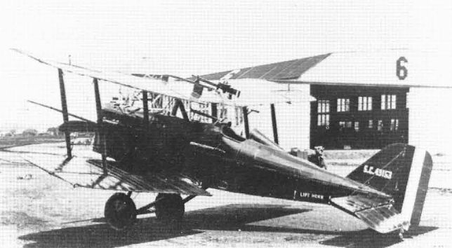
Curtiss completed only this one of 1,000 British S.E.5 fighters ordered but assembled 56 others that had been built in Britain.
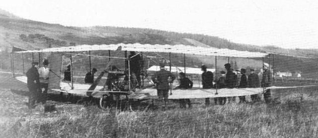
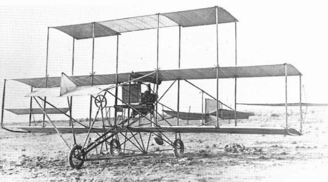
Aerodrome No.3, June Bug The June Bug, a further refinement of White Wing, was sponsored by Curtiss and was eminently successful with the same engine. First flown on 21 June, it made numerous flights, including a straightaway run of 1,140 yards (1,042 m) on the seventh flight. On 4 July, Curtiss made a pre-arranged flight to win the first task, or 'leg', of the Scientific American Trophy, which called for a straightaway flight of one kilometre (3,281 ft). After a couple of false starts, he won this with ease by flying over a mile (1.6 km) at a speed of 39 mph (62.76 km/h).
Span 42 ft 6 in (12,95 m); wing area 370 sq ft (34.37 sq m); gross weight 615 lb (279 kg).
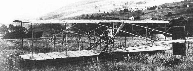
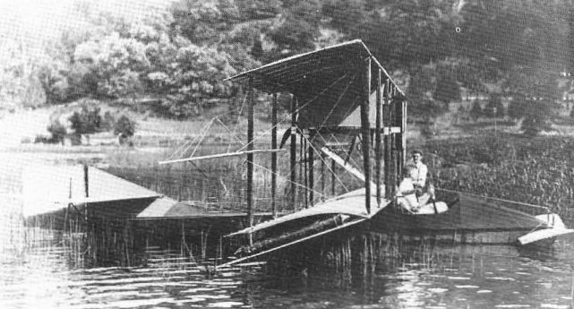
Loon - In November 1908, the June Bug was put on twin wood-frame pontoons covered with cloth and was renamed Loon. Attempts to fly from the water were unsuccessful due to the high hydrodynamic drag of the pontoons.
Span 42 ft 6 in (12,95 m); wing area 370 sq ft (34.37 sq m); gross weight 615 lb (279 kg).
Loon - In November 1908, the June Bug was put on twin wood-frame pontoons covered with cloth and was renamed Loon. Attempts to fly from the water were unsuccessful due to the high hydrodynamic drag of the pontoons.
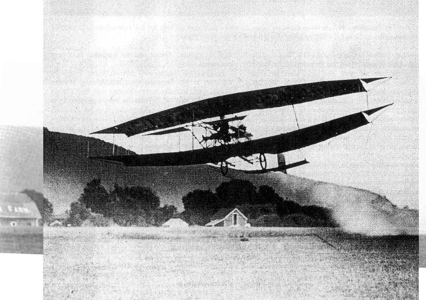
The AEA's third aircraft, the June Bug designed by Glenn Curtiss, won the Scientific American trophy for the first officially recorded flight of over a kilometre in the USA, accomplished by Curtiss on 4 July 1908.
A rare photograph of Glenn Curtiss' Loon (the June Bug on floats), which failed to become airborne during tests in 1908.
Aerodrome No.1, Red Wing The first AEA aeroplane was named Red Wing because of the colour of its fabric covering. It was a biplane with a movable elevator ahead of the wings and a fixed stabilizer behind. A movable rudder was provided, but no means of lateral control. Since it was to be flown from ice, it used skids for an undercarriage. The 'sponsor', or principal designer, was Lt Selfridge.
The first of two flights was made by Thomas Baldwin on 12 March, 1908, since Selfridge was absent on Army business. The flight covered a distance of 318 ft 11 in (97 m) and ended in a crash landing. This has been represented as the first public aeroplane flight in the United States, and figured in the subsequent controversies with the Wrights. The second flight, on 18 March, also ending in a crash, covered only 40 yards and proved the need for lateral control.
Span 43 ft 4 in (13.2 m); wing area 385 sq ft (35.76 sq m); gross weight 570 lb (258 kg); powerplant Curtiss 40 hp air-cooled V-8.
Aerodrome No.2, White Wing The second AEA aeroplane was White Wing, sponsored by Baldwin. It was very similar to Red Wing, except for the substitution of three wheels for the ice runners, and used the same engine. The most important innovation was the addition of movable lateral control surfaces on all four wingtips that later came to be called ailerons. In principle, these had the same effect as the Wright's wing-warping, but Curtiss claimed mechanical and control differences. The method of control reflected Curtiss's motorcyle experience - a yoke embraced the pilot's shoulders - when he wanted to bank for a turn, he leaned in the desired direction and the proper control movement was automatically applied.
White Wing made four flights, the first on 18 May, 1908, again with Baldwin at the controls. Distance was 93 yards (85 m) at a height of 10 ft (3 m). Longest flight was the third, at 339 yards (310m) with Curtiss flying. While Wing crashed on 23 May after McCurdy had flown 183 yards (167 m).
Span 42 ft 3 in (12.87 m); wing area 408 sq ft (37.9 sq m); gross weight 605 lb (274 kg).
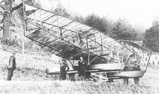
AEA Aerodrome No.2, While Wing. This was the first aeroplane to have a three-wheeled undercarriage.
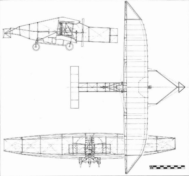
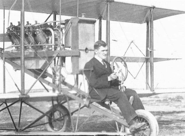
Aerodrome No.4, Silver Dart The Silver Dart was less famous than June Bug but was a far more successful flying machine. Sponsored by McCurdy, it had a 50 hp Curtiss water-cooled V-8 engine, biplane forward elevators, and no rear stabilizer. Instead of being connected directly, the engine drove the propeller by a chain and sprockets.
First flight was at Hammondsport on 6 December, 1908, with McCurdy flying. It was moved to Baddeck where it made the first flight in Canada on 23 February, 1909, again with McCurdy piloting.
Span 49 ft (14,93 m); wing area 420 sq ft (39 sq m); gross weight 860 lb (390 kg).
First flight was at Hammondsport on 6 December, 1908, with McCurdy flying. It was moved to Baddeck where it made the first flight in Canada on 23 February, 1909, again with McCurdy piloting.
Span 49 ft (14,93 m); wing area 420 sq ft (39 sq m); gross weight 860 lb (390 kg).
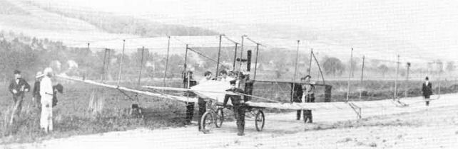
AEA Aerodrome No.4, the canard Silver Dart. was built at Hammondsport but did most of its flying in Nova Scotia, where it became the first aeroplane to fly in Canada.
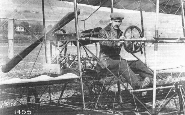
A grim-visaged Glenn Curtiss sits in the Silver Dart. Note the belt-driven propeller and individual carburellors ror each cylinder of the 50 hp V-8 engine.
Aerodrome No.4, Silver Dart
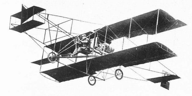
Beachey Tractor. Although he had left the Curtiss Exhibition Company in 1911 to do his own air show work, Lincoln Beachey retained a preference for Curtiss aeroplanes. Believing that the tractor type would be advantageous in his work, Beaehey collaborated with Curtiss early in 1913 on the design of a single-seat open-fuselage tractor biplane powered with a 90 hp Curtiss OX engine.
The tractor did not perform as expected, and Beachey had a scaled-down Curtiss pusher type built by Warren Eaton and later a tractor monoplane by Glenn L. Martin. He was killed when the Martin broke up in the air at San Francisco on 14 March, 1915.
The tractor did not perform as expected, and Beachey had a scaled-down Curtiss pusher type built by Warren Eaton and later a tractor monoplane by Glenn L. Martin. He was killed when the Martin broke up in the air at San Francisco on 14 March, 1915.

The second Curtiss tractor landplane design was an aerobatic machine designed to the requirements ofexhibition pilot Lincoln Beachey. It was not a success and Beachey went elsewhere for a tractor.
Evolution of the Curtiss Pusher
In the period 1909-12, the major Curtiss design and manufacturing effort was directed to the development of a basic model that historians later called 'The Curtiss Pusher'. This was a direct descendent of the final AEA design, the Silver Dart. The major change was redesign of the wings to simple rectangular shape with no dihedral and relocation of the ailerons to the mid-points of the forward wing struts. The aileron relocation was done partly for efficiency but mainly to separate those surfaces from the wing in an attempt to avoid infringement of the Wright patent.
The earliest models were all single seaters, with the pilot seated slightly ahead of the wing. The single water-cooled Curtiss engine of 26 to 90 hp was mounted between the wings behind him, driving a single propeller. Forward elevator controls were carried on bamboo booms ahead of the pilot while a fixed stabilizer and movable rudder were carried on booms behind. The ailerons were operated by shoulder yoke, the pilot leaning in the direction he wished to bank, a 'natural' function for Curtiss, the former motorcycle champion. As on the AEA types, the wings were originally covered on the top surfaces only.
Logical improvements such as more powerful engines and double-surfaced wings improved performance and made a practical vehicle of the pusher by allowing two people to be carried. Curtiss then developed a throw-over control column whereby the single control wheel could be moved from one pilot to the other. This was an improvement on the Contemporary Wright brothers' system, where two pilots shared one-and-a-half sets of controls, and developed into recognized 'left-seat' and 'right-seat' Wright pilots.
No designations were assigned to the early Curtiss models, which were merely identified according to their purchaser or the specific purpose for which they were built. As custom-built machines, each incorporated differences from its predecessor, and then took on additions that have further complicated the historians' recognition problems. Improved models illustrated in contemporary publications were identified only as 'The New Curtiss' or 'The XX Horsepower Curtiss',
Even after the assignment of official model designations, positive identification of individual Curtiss pushers of the 1910-13 era was impossible, A number of close copies were built by outsiders, who either used Curtiss-built machines as a guide or built from the workable plans that appeared in contemporary books and magazines and made various changes, Also, special features of aeroplanes custom-built by Curtiss, plus modifications and the use of parts from other models, further complicate the identity problem.
From 1909 into 1911, however, the major evolutionary changes in the pusher resulted in the recognition of the four distinct 'Types' listed here:
Type I - Single-seat machine with single-surface wings, biplane forward elevator on long forward booms, and fixed horizontal stabilizer located with rear rudder on long rear booms.
Type II -Single-seater similar to Type I except double-surfaced wings, ailerons relocated to rear struts.
Type III - Single- or two-seater with monoplane forward elevator on shortened booms, elevators added to horizontal stabilizer.
Type IV - Military model of Type III with wings built in short interchangeable sections to facilitate breakdown to small units for transport on Army wagons.
The Curtiss pushers started with a basic design and improved upon it, so the four definitive types seen from 1909 into 1911 can be regarded as developmental or evolutionary rather than experimental.
An oddity in the evolution of the pusher is inconsistency of later application of the forward elevator, which started as a biplane surface and then was simplified to a monoplane type before disappearing altogether. The one contribution that Augustus Herring is credited with making to Curtiss aeroplanes is the small forward vertical fin used on some of the 1909-11 models.
The need for the forward elevator was originally questioned by stunt pilot Lincoln Beachey, who successfully eliminated it from his exhibition machine late in 1910. While several experimental models subsequently flew without forward elevators, production aeroplanes continued to be delivered with them into 1912. On some Model Es, where the short forward booms formed an essential part of the bracing, the booms were retained after the elevators were removed subsequent to delivery. Four significant developmental pushers are now described:
Curtiss No.1, Gold Bug or Golden Flyer The first Curtiss-built aeroplane designated as such was the single-seat model ordered by the Aeronautical Society of New York on 2 March, 1909, The purchase price of $5,000 included instruction for two Society members, With no designation, No, 1 was initially called Gold Bug because of the golden tint of the varnished fabric but later officially became the Golden Flyer, Although built after the Herring-Curtiss affiliation, Curtiss specifically excluded No.1 from the inventory of the new company.
Curtiss-Herring No.1, Reims Racer At the urging of the Aeronautical Society ofNew York to represent it in the 1909 Gordon Bennett Cup Race in France, Curtiss built a larger version of No. 1 and installed a new 60 hp V-8 engine, which was a carefully-guarded secret until the racer was set up in France in August.
Flying against the clock rather than other aeroplanes, Curtiss completed the 20 km closed course at a world's record 43,35 mph (69,76 km/h). The Reims Racer was later used by Curtiss and his pilots for exhibition work and other record flights in the United States.
Hudson Flyer In 1909, Glenn Curtiss decided to try for the $10,000 prize posted by the New York World newspaper for the first flight between Albany, the capital city or New York State, and New York City. After many delays due to weather, the record 156-mile (251 km) flight was made on 29 May, 1910. The start was at Albany, with a refuelling stop at Poughkeepsie and a precautionary stop within the northern city limits of New York before the final landing on Governor's Island.
The Hudson Flyer was a stock model Curtiss or the period, modified for the flight. Since the entire route was over the Hudson, emergency flotation gear was added. To preclude nosing over on alighting on water, a hydrovane was installed ahead of the nosewheel at the suggestion of Charles Willard, who had made two unintentional alightings in the Golden Flyer. To carry the weight or the extra equipment and fuel, the area of the upper wing was increased by adding strut-braced extensions to the tips.
Beachey Special Curtiss exhibition pilot Lincoln Beachey, whose early fame came from dirigible racing, was the leading American stunt pilot of the 1911-14 period and was the first American pilot to perform a loop. He could have been the first in the world, but when he proposed the idea to Curtiss in 1912, Curtiss said it couldn't be done and forbade him to try.
In 1911, to improve Beachey's performance, Curtiss built him a special extra-strength and higher powered showplane. As requested, this did not have forward elevators since Beachey had already proved that the standard model could do without them. Beachey used his Special to set the world's altitude record or 11,642 ft (3,548 m) on 20 August, 1911.
By mid-1911, when Curtiss pushers were pretty well standardized and being manufactured in what could be considered production quantities, Curtiss began to use specific designations in its advertizing. The following descriptions of officially-designated D and E models are reproduced verbatim from the 1911 Curtiss Aeroplane Company catalogue. The Curtiss A to C designations, if used at all, cannot be correlated to specific aeroplanes or configurations; the designation Model C is seen on some photographs or June Bug, apparently added by later misguided historians.
Model D
SPECIFICATIONS
Width - Planes, over all, 33 feet, 4 inches.
Length - Front to rear control, 25 feet, 9 inches.
Height - From ground to highest points, 7 feet 5 1/2 inches.
DESCRIPTION AND PRICES
Model D-4 - Equipped with a 4-cylinder, 40 H. P., water-cooled Curtiss motor. An excellent machine for exhibition work, endurance, etc. Speed, 45 miles per hour. Weight ready for flight, 550 pounds. Weight, packed for shipment, 950 pounds. Price, complete for shipment. $4,500
Model D-8 - Equipped with an 8-cylinder, 60 H. P., water-cooled Curtiss motor. Entire outfit identical with that used by the famous aviators of The Curtiss Exhibition Co. The safest machine, and the most suitable for a confined space. Speed 60 miles per hour. Weight, ready for flight, 650 pounds. Weight, packed for shipment, 1,000 pounds. Price, complete for shipment $5,000
Model D-8-75 - Same as Model D, but equipped with an 8-cylinder, 75 H. P., water-cooled Curtiss motor. Capable of developing a speed of 70 miles an hour. For speed and cross-country races. Weight, ready for flight, 700 pounds. Weight, packed for shipment, 1,050 pounds. Price, complete for shipment $3,500
Model E
SPECIFICATIONS
Width - Planes, over all, 35 feet, 4 inches.
Length - Front to rear control, 25 feet, 9 inches.
Height - From ground to highest point, 8 feet.
DESCRIPTION AND PRICES
Model E-4 - Equipped with a 4-cylinder, 40 h.p. water-cooled Curtiss motor. This machine is a slow, strong flying aeroplane, especially suitable for aviation schools and beginners. It is also available for high, dry altitudes. Speed, 40 miles per hour. Weight, ready for flight, 600 pounds. Weight, packed for shipment, 1000 pounds. Price, complete for shipment $4,500
Model E-8 - Equipped with an 8-cylinder, 60 h. p. water-cooled Curtiss motor. A machine that combines speed with the advantages of weight-carrying. Equipped with the Curtiss alternating dual control system. A machine that makes aviation a sport. Speed, 55 miles per hour. Weight, ready for flight, 700 pounds. Weight, packed for shipment, 1050 pounds. Price, complete for shipment $5,000
Model E-8-75 - The same as model E-8, but equipped with an 8-cylinder, 75 h. p. Curtiss motor. The surplus power gives greater speed as well as more weight-carrying possibilities. Speed, 60 miles per hour. Weight, ready for flight, 750 pounds. Weight, packed for shipment, 1,100 pounds. Price, complete for shipment $5,500
DESCRIPTION AND PRICES
Model D-8 - Exhibition type with hydro equipment, in addition to the regular chassis. Price, complete. $5,500
Model E-8-75 - The "triad" passenger carrying hydroaeroplane, which is identical with Model E when the hydro is not attached. This machine is equipped with a 75 h. p. motor. Price $6,000
With standardized Curtiss pushers in production and being advertized world-wide, business was brisk by 1912. The aeroplane and engine factories were enlarged and licences were issued for the manufacture of pushers in other countries.
While a basic design was sold, there were special custom variations. Aviatrix Ruth Law, for example, had learned to fly on a Wright aeroplane with its peculiar control system and could not make the transition to the Curtiss system. Consequently, her custom-built Curtiss D was fitted with Wright controls.
Between them, the US Army and Navy bought twelve Curtiss land plane pushers in 1911 and 1912, and these are now discussed.
The US Army's second aeroplane was an existing model ordered on 13 March, 1911, for $6,000 and was delivered the same month. Identified as Signal Corps Aeroplane No.2, this was a single-seat Model D powered with a 60 hp Curtiss engine. The engine was soon replaced with a 40 hp model and the front elevator was removed some time later. No.2 ended its days as a 'Penguin' ground trainer after the Army grounded all of its pusher trainers in February 1914. Rebuilt to original configuration, it is now in The National Air Museum of the Smithsonian Institution.
Three two-seat Curtiss Es also went to the Army - S.C. numbers 6, 8, and 23. The original 40 hp engine of No.6 was exchanged for the 60 hp model of the smaller S.C. No.2, S.C.8 was eventually converted to a seaplane, and S.C.23 was sold out of the Service after the pushers were grounded.
The poor safety records of both the Wright and Curtiss pusher trainers at the Army's North Island school brought about a demand for safer tractor-type equipment and led directly to the development of the Curtiss J and N models that culminated in the immortal IN series.
Of eight Curtiss pushers bought by the US Navy between 1911 and 1913, only one was delivered as a landplane, and it was soon converted to a seaplane.
Shortly after World War I, a special 1912-style Curtiss pusher was built under Glenn Curtiss's personal direction at Garden City, evidently for nostalgic reasons. Such minor refinements as improved fittings and a revised control system featuring a rudder bar and wheel control for the ailerons were incorporated. Long a fixture at Curtiss Field, this machine was in the Roosevelt Field Museum until World War II and is now at The National Air Museum.
The first Curtiss aeroplane, the Golden Flyer built for the Aeronautical Society of New York.
Glenn Curtiss and Curtiss-Herring No.1, the aeroplane with which he won the 1909 Gordon Bennett Cup at Reims, France.

The Hudson Flyer in which Glenn Curtiss won $10,000 for a flight from Albany to New York City in May 1909. The extended upper wing supported the weight of the emergency flotation gear used for the 156-mile overwater flight
The Model E was a two-seater, but with only 40 hp, the US Army's Aeroplane No.6 of 1911 was rigged as a single-seater.
A true replica of a 1912 Curtiss pusher built by Glenn Curtiss and associates at Garden City after World War I. Powerplant was a war-surplus Curtiss OX-5.

Early Curtiss single-seat Model D.
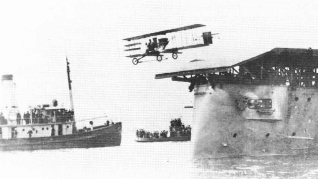
An early Curtiss promotional effort resulted in pilot Eugene Ely making the first take off of an aeroplane from a ship, on 10 November, 1910. This is the second take off, made after landing on the uss Pennsylvania, on 18 January, 1911.
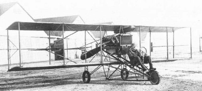
Triplane adaptation of Curtiss Model E with monoplane forward elevator
Famous acrobatic pilot Lincoln Beachey seated in his special Curtiss pusher fitted with standard controls, including shoulder-yoke for the ailerons.

aviatrix Ruth Law learned to fly on a Wright aeroplane and had to have this entirely difierent control system installed in her Curtiss.

Curtiss-Herring No.1 Reims Racer
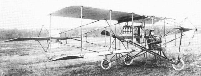
Ely Monoplane. In 1910, Curtiss exhibition pilot Eugene Ely ordered a monoplane to be built by Curtiss. While this was essentially a single-wing version of the current Curtiss biplane, it was Ely's concept and should not be considered a Curtiss design.
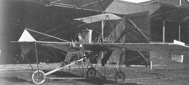
The Ely monoplane was built to the special order of Curtiss exhibition pilot Eugene Ely and was not a true Curtiss design.
Seaplane Development
The first American attempt to fly from the water was made by the AEA in 1908 with the Loon, but it was unable to take off. In June 1910, Curtiss successfully alighted on Lake Keuka in a Type III pusher with a canoe secured beneath it; however, the aeroplane would not take off for the same reason as the Loon - the high hydrodynamic drag of the rounded canoe hull prevented the machine from reaching flying speed.
Curtiss soon realized that a flat-bottomed float could plane over the water, offering less drag and consequently more speed for a given power. A long series of experimental pontoons, or floats, was then developed and tried on standard Curtiss pushers at San Diego during winter 1910-11.
Although the Frenchman Henri Fabre had successfully taken off from water in a powered aeroplane on 28 March, 1910, Curtiss is recognized as the inventor of the practical seaplane. The original short Curtiss floats had flat bottoms for their entire length; later, long designs featured the hydroplane step, located slightly behind the aeroplane's centre of gravity, that Curtiss had developed for his flying-boat in 1912, combined with V-bottoms.
The single main float with wingtip floats standardized by Curtiss early in 1911 remained in use on most US Navy seaplanes to the end of their service in 1960; the twin-float arrangement of the 1908 Loon is in universal use on civil seaplanes today.
Experimental Hydros, 1911
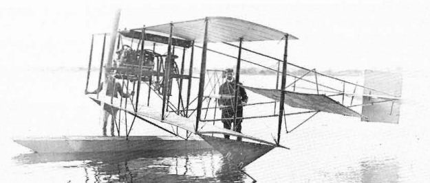
The first successful flight of what was originally called a hydroaeroplane or simply hydro, but is now known as a seaplane, was made on 26 January, 1911. It used a clumsy tandem-float arrangement featuring a main float six ft (1.82 m) wide by five ft (1.52 m) long under the centre section, a smaller float forward, and a hydrofoil ahead of that to keep the bow from submerging at high speed. The wide design of the main float served two purposes. By being wide it was expected to function as an auxiliary wing to generate useful lift; also, its width would keep the spray pattern well outboard of the pusher propeller. Being short, it did not provide longitudinal stability on the water thus necessitating the forward float.
By 1 February, a new arrangement was introduced, comprising a sled-shaped single float 12 ft (3,65 m) long, two ft (60 cm) wide and a foot (30 cm) deep, under the pilot and engine to provide longitudinal stability; small floats for lateral stability were under the wingtips.
At first, the main float was not compartmented. On a flight at Hammondsport, Curtiss took off in a hydro but a considerable amount of water had got into the float and as he nosed down to alight, all the water ran to the bow of the float and made the machine so nose heavy that Curtiss was unable to raise the nose and crashed into the lake. He recognized the problem as soon as it appeared and fortunately survived to correct it.
An early refinement of the hydro was to eliminate the booms that supported the forward elevator and place a monoplane elevator on the bow of the float. As on contemporary landplanes, the hydro's forward elevators were soon eliminated.
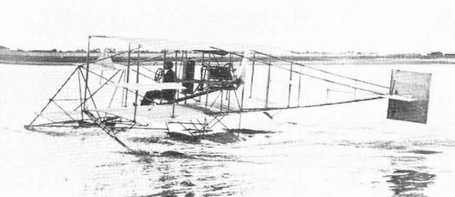
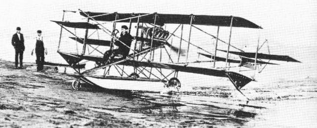
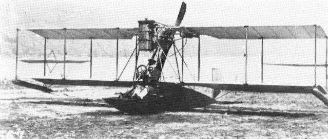
Tractor Hydro. The second Curtiss hydro was a notable exception to the standard pusher design. The un-named machine that Curtiss used for his flight from North Island to the cruiser Pennsylvania was an otherwise standard Type III pusher airframe with the engine installed ahead of the wing as a tractor to keep the propeller out of the spray. The pilot was seated behind the wings and the forward elevator was eliminated. Curtiss didn't like the arrangement mainly because of the discomfort of sitting in the propeller blast and engine exhaust; the problem of spray on the propeller on subsequent pusher seaplanes was reduced somewhat by the addition of horizontal spray deflectors to the top of the main float ahead of the propeller.
Triad. With the conventional landplane converted to water operations by the substitution of pontoons for wheels, it was only natural to develop an aeroplane to operate from both elements. Curtiss achieved this by adding retractable wheels under the lower wings of a hydro and adding a nosewheel to the bow of the float. The resulting amphibian, named Triad by Curtiss, was successfully demonstrated at North Island on 25 February, 1911.
Although still in use today, the popularity of amphibious floatplanes has always been limited by the double weight handicap of the floats and the necessary wheel-retracting mechanism. The most popular amphibians have all been flying-boat types.
US Navy A-1. The Navy's first aeroplane, a 50 hp Curtiss Model E seaplane costing $5,500, was tested by Glenn Curtiss on 30 June, 1911, and turned over to Navy pilot T. G. Ellyson at Hammondsport the same day. On 7 July, the75 hp V-8 engine originally intended for the A-1 was installed. The A-1, later AH-1 under the 1914 Naval designation system, operated as a straight seaplane, as a Triad amphibian, and as a landplane.
Among the experiments undertaken with A-1 were take off down an inclined wire, with a groove in the bottom of the float to maintain alignment, and the Navy's first attempt to launch an aeroplane from a compressed-air catapult. After sixty flights totalling 285 hours, plus numerous rebuilds, A-1 is believed to have been struck off charge on 16 October, 1914.
By the autumn of 1911 Curtiss was advertizing hydros on the open market. The standardized float gear was available for an additional $500 when buying a standard Model D or E land plane. The hydros were nearly as popular as the landplanes and were licensed to overseas manufacturers in 1912.
The US Navy bought fourteen pushers with detail variations between 1911 and 1914. The combined Navy Type I serial numbers were A-1, A-2 (delivered as a landplane but converted to hydro), A-3, A-4, AH-8, AH-9, and AH-11/18. AH-8 was turned over to the Army, was still in Army hands in 1919, and was then stored. It was refurbished for a brief flight on 10 February, 1928. AH-9 was rebuilt and redesignated as an AH-8 type, Navy serial No. A-83.
The first American attempt to fly from the water was made by the AEA in 1908 with the Loon, but it was unable to take off. In June 1910, Curtiss successfully alighted on Lake Keuka in a Type III pusher with a canoe secured beneath it; however, the aeroplane would not take off for the same reason as the Loon - the high hydrodynamic drag of the rounded canoe hull prevented the machine from reaching flying speed.
Curtiss soon realized that a flat-bottomed float could plane over the water, offering less drag and consequently more speed for a given power. A long series of experimental pontoons, or floats, was then developed and tried on standard Curtiss pushers at San Diego during winter 1910-11.
Although the Frenchman Henri Fabre had successfully taken off from water in a powered aeroplane on 28 March, 1910, Curtiss is recognized as the inventor of the practical seaplane. The original short Curtiss floats had flat bottoms for their entire length; later, long designs featured the hydroplane step, located slightly behind the aeroplane's centre of gravity, that Curtiss had developed for his flying-boat in 1912, combined with V-bottoms.
The single main float with wingtip floats standardized by Curtiss early in 1911 remained in use on most US Navy seaplanes to the end of their service in 1960; the twin-float arrangement of the 1908 Loon is in universal use on civil seaplanes today.
Experimental Hydros, 1911
The first successful flight of what was originally called a hydroaeroplane or simply hydro, but is now known as a seaplane, was made on 26 January, 1911. It used a clumsy tandem-float arrangement featuring a main float six ft (1.82 m) wide by five ft (1.52 m) long under the centre section, a smaller float forward, and a hydrofoil ahead of that to keep the bow from submerging at high speed. The wide design of the main float served two purposes. By being wide it was expected to function as an auxiliary wing to generate useful lift; also, its width would keep the spray pattern well outboard of the pusher propeller. Being short, it did not provide longitudinal stability on the water thus necessitating the forward float.
By 1 February, a new arrangement was introduced, comprising a sled-shaped single float 12 ft (3,65 m) long, two ft (60 cm) wide and a foot (30 cm) deep, under the pilot and engine to provide longitudinal stability; small floats for lateral stability were under the wingtips.
At first, the main float was not compartmented. On a flight at Hammondsport, Curtiss took off in a hydro but a considerable amount of water had got into the float and as he nosed down to alight, all the water ran to the bow of the float and made the machine so nose heavy that Curtiss was unable to raise the nose and crashed into the lake. He recognized the problem as soon as it appeared and fortunately survived to correct it.
An early refinement of the hydro was to eliminate the booms that supported the forward elevator and place a monoplane elevator on the bow of the float. As on contemporary landplanes, the hydro's forward elevators were soon eliminated.
Tractor Hydro. The second Curtiss hydro was a notable exception to the standard pusher design. The un-named machine that Curtiss used for his flight from North Island to the cruiser Pennsylvania was an otherwise standard Type III pusher airframe with the engine installed ahead of the wing as a tractor to keep the propeller out of the spray. The pilot was seated behind the wings and the forward elevator was eliminated. Curtiss didn't like the arrangement mainly because of the discomfort of sitting in the propeller blast and engine exhaust; the problem of spray on the propeller on subsequent pusher seaplanes was reduced somewhat by the addition of horizontal spray deflectors to the top of the main float ahead of the propeller.
Triad. With the conventional landplane converted to water operations by the substitution of pontoons for wheels, it was only natural to develop an aeroplane to operate from both elements. Curtiss achieved this by adding retractable wheels under the lower wings of a hydro and adding a nosewheel to the bow of the float. The resulting amphibian, named Triad by Curtiss, was successfully demonstrated at North Island on 25 February, 1911.
Although still in use today, the popularity of amphibious floatplanes has always been limited by the double weight handicap of the floats and the necessary wheel-retracting mechanism. The most popular amphibians have all been flying-boat types.
US Navy A-1. The Navy's first aeroplane, a 50 hp Curtiss Model E seaplane costing $5,500, was tested by Glenn Curtiss on 30 June, 1911, and turned over to Navy pilot T. G. Ellyson at Hammondsport the same day. On 7 July, the75 hp V-8 engine originally intended for the A-1 was installed. The A-1, later AH-1 under the 1914 Naval designation system, operated as a straight seaplane, as a Triad amphibian, and as a landplane.
Among the experiments undertaken with A-1 were take off down an inclined wire, with a groove in the bottom of the float to maintain alignment, and the Navy's first attempt to launch an aeroplane from a compressed-air catapult. After sixty flights totalling 285 hours, plus numerous rebuilds, A-1 is believed to have been struck off charge on 16 October, 1914.
By the autumn of 1911 Curtiss was advertizing hydros on the open market. The standardized float gear was available for an additional $500 when buying a standard Model D or E land plane. The hydros were nearly as popular as the landplanes and were licensed to overseas manufacturers in 1912.
The US Navy bought fourteen pushers with detail variations between 1911 and 1914. The combined Navy Type I serial numbers were A-1, A-2 (delivered as a landplane but converted to hydro), A-3, A-4, AH-8, AH-9, and AH-11/18. AH-8 was turned over to the Army, was still in Army hands in 1919, and was then stored. It was refurbished for a brief flight on 10 February, 1928. AH-9 was rebuilt and redesignated as an AH-8 type, Navy serial No. A-83.
The first successful Curtiss seaplane of January 1911 had tandem floats and a forward hydrovane.
The second Curtiss seaplane had the engine forward and the pilot aft. Glenn Curtiss used this machine to fly from North Island to the cruiser Pennsylvania anchored in San Diego Bay.
Glenn Curtiss demonstrates the Triad, the first successful amphibian, at San Diego in February 1911.
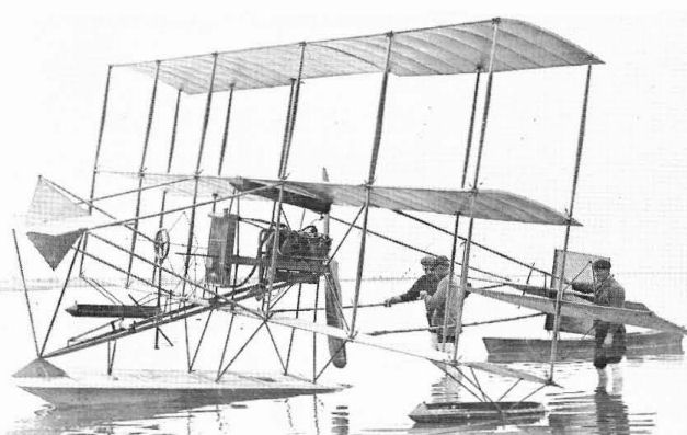
The third wing on this mid-1911 Curtiss hydro generated 200 Ib of additional lift.
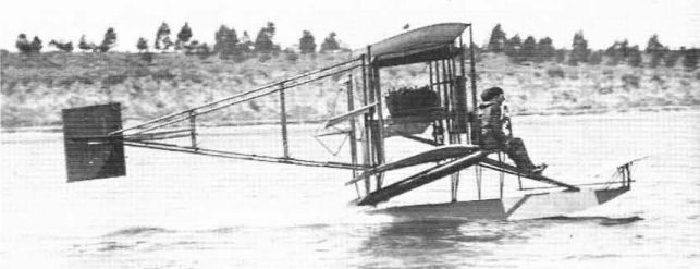
The standard Curtiss hydro of late 1911 still had the forward elevator. but the forward booms were no longer used and the elevator was mounted on the float.
A-1, Triad
Flying-boat Development
Following the perfection of the hydro aeroplane or seaplane, which was simply a landplane with floats substituted for wheels, Curtiss sought to develop a true flying-boat. The distinction lay in the fact that the boat-like hull formed an integral part of the structure rather than being an interchangeable accessory as on the hydro. Although others were working on the same idea concurrently, Glenn Curtiss is recognized as the inventor of the aeroplane configuration known as the flying-boat. The basic layout that he developed in 1912 became the world standard for single-engined flying-boats and is still being used.
Flying-boat No.1. The first Curtiss flying-boat, tried at San Diego on 10 January, 1912, was more a hydro than a true boat. A wide hull, only slightly longer than the standard Curtiss pontoon, was attached under the lower wing of the de-engined airframe of the tractor seaplane. A single 60 hp engine was mounted in the hull and drove two tractor propellers through chains in Curtiss's only deliberate adaptation of a Wright brothers' feature. There were two side-by-side seats in a cockpit behind the wing.
Although No.1 was unable to take off, the experiment did indicate that the flying-boat concept was practicable. Subsequent developments were made at Hammondsport.
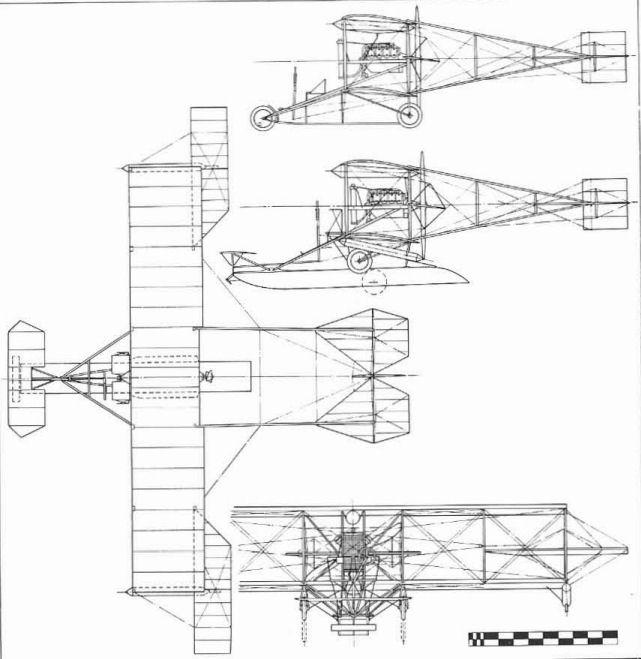
Flying-boat No.2, The Flying Fish. The first successful flying-boat, built at Hammondsport, featured a full-length flat-bottomed hull that supported both the wings and tail. To keep the horizontal tail surfaces out of the water, they were sited part-way up the long vertical fin.
The engine was a 75 hp Curtiss Model O installed between the wings as on standard pushers. An indication of the fact that Flying-boat No.2 was built quickly and cheaply to prove a concept rather than to achieve optimum performance is shown by the initial use of an old set of 1910-style single surface wings. Forward elevators were also fixed to the bow at a time when they were being omitted from production aeroplanes. Flying-boat No.2 underwent considerable modification and refinement within a short period, ending up with double surface E-75 wings and no forward elevators. In this configuration, it was widely publicized as The Flying Fish.
At first, Flying-boat No.2 would not leave the water; the hydrodynamic drag of the hull prevented it from reaching flying speed. After observing the difficulty from an accompanying motorboat, Curtiss suggested breaking the smooth line of the bottom with a step just behind the centre of gravity.
Incorporation of the hydroplane step had two beneficial effects. First, it removed nearly half the length of the hull from contact with the water at near-take off speeds; second, it permitted a degree of rotation at take off speed to allow the wings to reach the higher angle of attack needed for take off. Too much rotation, however, put the rear of the hull back in the water and the added drag killed the take off speed. The step worked so well that Curtiss patented it, along with vents that allowed air to bleed into the water cavity behind the step to further reduce drag at take off speed.
Fitted with the step, Flying-boat No.2 made its first flight in July 1912.
Following the perfection of the hydro aeroplane or seaplane, which was simply a landplane with floats substituted for wheels, Curtiss sought to develop a true flying-boat. The distinction lay in the fact that the boat-like hull formed an integral part of the structure rather than being an interchangeable accessory as on the hydro. Although others were working on the same idea concurrently, Glenn Curtiss is recognized as the inventor of the aeroplane configuration known as the flying-boat. The basic layout that he developed in 1912 became the world standard for single-engined flying-boats and is still being used.
Flying-boat No.1. The first Curtiss flying-boat, tried at San Diego on 10 January, 1912, was more a hydro than a true boat. A wide hull, only slightly longer than the standard Curtiss pontoon, was attached under the lower wing of the de-engined airframe of the tractor seaplane. A single 60 hp engine was mounted in the hull and drove two tractor propellers through chains in Curtiss's only deliberate adaptation of a Wright brothers' feature. There were two side-by-side seats in a cockpit behind the wing.
Although No.1 was unable to take off, the experiment did indicate that the flying-boat concept was practicable. Subsequent developments were made at Hammondsport.
Flying-boat No.2, The Flying Fish. The first successful flying-boat, built at Hammondsport, featured a full-length flat-bottomed hull that supported both the wings and tail. To keep the horizontal tail surfaces out of the water, they were sited part-way up the long vertical fin.
The engine was a 75 hp Curtiss Model O installed between the wings as on standard pushers. An indication of the fact that Flying-boat No.2 was built quickly and cheaply to prove a concept rather than to achieve optimum performance is shown by the initial use of an old set of 1910-style single surface wings. Forward elevators were also fixed to the bow at a time when they were being omitted from production aeroplanes. Flying-boat No.2 underwent considerable modification and refinement within a short period, ending up with double surface E-75 wings and no forward elevators. In this configuration, it was widely publicized as The Flying Fish.
At first, Flying-boat No.2 would not leave the water; the hydrodynamic drag of the hull prevented it from reaching flying speed. After observing the difficulty from an accompanying motorboat, Curtiss suggested breaking the smooth line of the bottom with a step just behind the centre of gravity.
Incorporation of the hydroplane step had two beneficial effects. First, it removed nearly half the length of the hull from contact with the water at near-take off speeds; second, it permitted a degree of rotation at take off speed to allow the wings to reach the higher angle of attack needed for take off. Too much rotation, however, put the rear of the hull back in the water and the added drag killed the take off speed. The step worked so well that Curtiss patented it, along with vents that allowed air to bleed into the water cavity behind the step to further reduce drag at take off speed.
Fitted with the step, Flying-boat No.2 made its first flight in July 1912.
The first successful Curtiss flying-boat was assembled and flown at Hammondsport using an old set of single-surface wings and a forward elevator.
Other Experimental Flying-boats
Several other flying-boats were built immediately after No.2 to try different hull designs, engine positions and other features. They carried no known designations and their constant modifications have complicated the identification problem. Three are described here.
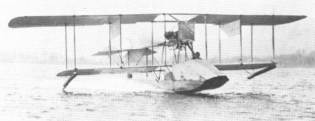
Freak Boat/C-1/AB-1. Identified only as 'Freak Boat' in later Curtiss photographic records, this 'boat had a full-length hull but the pilots were in the open as on the standard hydro. The close gap of the equal-span wings lowered the upper wing to the top of the pusher engine. The horizontal tail was mounted on struts above the hull and the square rudder was used without a vertical fin.
After extensive modification that included entirely new tail surfaces and shorter unequal-span wings, this 'boat was sold to the Navy in November 1912, and designated C-1. In March 1914, the designation was changed to AB-1. As C-1, it made the first successful catapult launch of a flying-boat on 12 December, 1912, at Washington Navy Yard. Its last flight was on 1 April, 1914.
Tadpole. Identified only as Tadpole, this flying-boat is representative of several that had their hulls built in the form of elongated main hydro floats with the area between the top of the float and the wings built up with a light fabric-covered superstructure. On Tadpole, the tail surfaces were carried above the hull on struts. The wing assembly pivoted about the rear spar to provide a variable-incidence feature; the pusher engine was stabilized by a tie rod between the end of the propeller shaft and the tail surfaces.
A-2/OWL/E-1/AX-1. The A-2 was the Navy's second aeroplane, a Curtiss Model E delivered as a landplane on 13 July, 1911. The original engine was a four-cylinder 50 hp model, soon changed to a 60 hp V-8.
The A-2 was converted to a seaplane in June 1912. It was further modified at Hammondsport in October 1912 to enclose the crew in a fabric-covered superstructure between the float and the wings, eliminating the interchangeability feature and making the A-2 a short-hull flying-boat. Further experimentation added retractable wheels to give amphibian capability; the unofficial designation of OWL was applied to signify operation 'over water and land'. The Navy designation was changed to E-1 in September 1913 and finally to AX-1 in March 1914. It was wrecked on 27 November, 1915, after 91 flights.
Testing of the experimental flying-boats of 1912 soon resulted in a marketable design. The earliest production versions, which were undesignated, had hulls with strong lower structure and a light upper superstructure filling the underwing gap and enclosing the two-man crew. Wings, with interplane ailerons, were sometimes of equal span and sometimes had extended upper wingtips. The design culminated in the Model F, which was immediately popular and enjoyed wide sale to private owners in the United States and to foreign governments.
Several other flying-boats were built immediately after No.2 to try different hull designs, engine positions and other features. They carried no known designations and their constant modifications have complicated the identification problem. Three are described here.
Freak Boat/C-1/AB-1. Identified only as 'Freak Boat' in later Curtiss photographic records, this 'boat had a full-length hull but the pilots were in the open as on the standard hydro. The close gap of the equal-span wings lowered the upper wing to the top of the pusher engine. The horizontal tail was mounted on struts above the hull and the square rudder was used without a vertical fin.
After extensive modification that included entirely new tail surfaces and shorter unequal-span wings, this 'boat was sold to the Navy in November 1912, and designated C-1. In March 1914, the designation was changed to AB-1. As C-1, it made the first successful catapult launch of a flying-boat on 12 December, 1912, at Washington Navy Yard. Its last flight was on 1 April, 1914.
Tadpole. Identified only as Tadpole, this flying-boat is representative of several that had their hulls built in the form of elongated main hydro floats with the area between the top of the float and the wings built up with a light fabric-covered superstructure. On Tadpole, the tail surfaces were carried above the hull on struts. The wing assembly pivoted about the rear spar to provide a variable-incidence feature; the pusher engine was stabilized by a tie rod between the end of the propeller shaft and the tail surfaces.
A-2/OWL/E-1/AX-1. The A-2 was the Navy's second aeroplane, a Curtiss Model E delivered as a landplane on 13 July, 1911. The original engine was a four-cylinder 50 hp model, soon changed to a 60 hp V-8.
The A-2 was converted to a seaplane in June 1912. It was further modified at Hammondsport in October 1912 to enclose the crew in a fabric-covered superstructure between the float and the wings, eliminating the interchangeability feature and making the A-2 a short-hull flying-boat. Further experimentation added retractable wheels to give amphibian capability; the unofficial designation of OWL was applied to signify operation 'over water and land'. The Navy designation was changed to E-1 in September 1913 and finally to AX-1 in March 1914. It was wrecked on 27 November, 1915, after 91 flights.
Testing of the experimental flying-boats of 1912 soon resulted in a marketable design. The earliest production versions, which were undesignated, had hulls with strong lower structure and a light upper superstructure filling the underwing gap and enclosing the two-man crew. Wings, with interplane ailerons, were sometimes of equal span and sometimes had extended upper wingtips. The design culminated in the Model F, which was immediately popular and enjoyed wide sale to private owners in the United States and to foreign governments.
The Freak Boat of 1912 had such a small wing gap that the engine had to be mounted near the upper wing. After extensive modification, this machine was sold to the US Navy as C-1.
A later and more refined Curtiss flying-boat, known only as the Tadpole, taking off at Hammondsport.
Model F
1913 Model. The 1913 Model F used the early composite hull construction and what were essentially Model E-75 wings with strut-braced extensions of the upper wing. Because of its many 'old' features relative to the 1914 F-boat, the 1913 model has sometimes (and erroneously) been referred to by historians as the E-boat in disregard of the recognized Curtiss Model E landplane and the Navy's E-designation.
Model F (1913)
Two seats.
Span 41 ft 8 in (12.69 m); length 27 ft 4 in (8.33 m).
Gross weight 1,760 lb (798 kg).
Maximum speed 54.8 mph (88.19 km/h); climb 1,200 ft (365 m) in 7.6 min; endurance 4 hr.
Powerplant 75 hp Curtiss O.
1914 Model. The standardized Model F of 1914 differed noticeably from the 1913 versions, particularly in having equal-span wings with rounded tips projecting beyond the end struts and a hull with full-depth primary structure and a rounded wood veneer foredeck. On some civil models, the foredeck hinged forward to form a gangplank for crew movement to or from a beach. An additional feature was a diagonal strut from the engine mount to the lower forward hull structure, intended to protect the crew from a falling engine in a crash. This became known as the Goodier strut since it was installed as the result of Army Lt Lewis Goodier's crash in the Army's first F-boat, S.C.15.
US Navy C-1/C-5 (AB-l/5). The Navy bought five early flying-boats from Curtiss and designated them Navy Type C. Numbering was in sequence of delivery, but the 'boats were not identical, ranging from one of the experimentals modified to near-production standard (C-1/AS-1) to the stock F-boat. On 30 August, 1913, the C-2 flew at Hammondsport under the complete control of a Sperry gyroscopic automatic pilot. The C-boats were redesignated as ABs with the same sequential numbers on 25 March, 1914.
The AB-3 became the first US military aircraft to see action. It was transported with AH-3 to Vera Cruz, Mexico, aboard the cruiser Birmingham, arriving on 21 April, 1914. On 25 April, Lt P. N. L. Bellinger piloted AB-3 on a reconnaissance mission over the city of Vera Cruz and surveyed the harbour for mines. AB-3 later had its wings shortened and was used as a non-flying 'Penguin' taxying-trainer.
US Army 15, 34, 49. The three Curtiss flying-boats delivered to the Army between November 1912 and December 1915, were identified in service only by their Signal Corps numbers. In detail they ranged from composite-hull 'E-boat' (No.15) to the standardized 1914 model mahogany-bull F-boat (Nos 34, 49).
Model F (Revised)
The basic single-engine pusher-type F-boat of 1913-14 was ordered in small numbers by the Navy to the end of 1916. After US entry into the war in 1917, orders were increased when the design was chosen as the Navy's standard primary training flying-boat; 144 were procured after April 1917 and production continued into 1918 until replaced by the MF, yet the F was overlooked in the 1935 redesignation.
The 1917-18 Model Fs were greatly improved over the 1914 model, the principal change being redesign of the control system to delete the shoulder-yoke aileron control, both Services having agreed to standardize on the Deperdussin system in August 1916. Various wing modifications were tried on a few examples, among them extension of the upper wing span to 45 ft 1 3/8 in (13,75 m) and transfer of the interplane ailerons to the upper wing. Several F-boats were fitted out as aerial ambulances, with provision for a litter to be carried on top of the hull behind the cockpit. Powerplant was the 100 hp Curtiss OXX-3.
Costing $7,500, less GFE, new, surplus F-boats came on the postwar market priced at $1,750 and saw relatively wide use by private owners. US Navy serial numbers: A145, A146, A386, A387, A390/393 (4), A408, A752/756 (5), A2279/2281 (3), A2295/2344 (50), A3328/3332 (5), A4079/4108 (30), A4349/4402 (54), A5258
Revised 1917 Model F
Trainer flying-boat. Two pilots.
100 hp Curtiss OXX-3.
Span 45 ft 1 3/8 in (13,75 m); length 27 ft 9 3/4 in (8,47 m); height 11 ft 2 13/16 in (3,42 m); wing area 387 sq ft (35,95 sq m).
Empty weight 1.860 lb (843,68 kg); gross weight 2,460 lb (1.115,83 kg).
Maximum speed 69 mph (111 km/h); climb to 2,300 ft (701 m) 10 min; service ceiling 4,500 ft (1.372 m); endurance 5,5 hr at cruising speed.
Model K (Model 4)
The Model K of 1915 was a logical development of the popular Model F flying-boat. It was larger, more refined in detail, and was powered with a 150 hp Curtiss V-X engine in the now traditional between-wings pusher location. Other than size, the distinctive differences between the F and the K were the heavy stagger of the K wings, the use of ailerons inset into the upper wing, and a V-bottom for the hull.
The K-boats did not sell well in the US but enjoyed a brisk export trade. Some, sold to Russia and delivered after many delays, were unseaworthy when set up because they had lain in their shipping crates so long that their wooden hulls had dried out and opened up numerous cracks.
Model K
Three-seat military flying-boat. 150 hp Curtiss V-X.
Span 55 ft 9 7/8 in (17,01 m); length 31 ft 5 1/4 in (9,58 m); wing area 592 sq ft (54,99 sq m).
Empty weight 2,700 lb (1,225 kg); gross weight 3,900 lb (1,769 kg) .
Maximum speed 70 mph (112,65 km/h); rate of climb 150 ft/min (0,76 m/sec); range 364 miles (586 km).
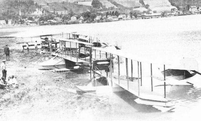
Curtiss seaplanes on Lake Keuka, Hammondsport, NY, in 1914.
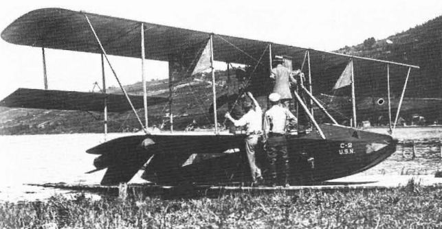
The Navy C-2 was essentially a stock Curtiss Model F flying-boat with extra span added to the top wing. This was used for early automatic pilot experiments in August 1913.

The Model K of 1915 showed the influence of both the F and J designs.

Model F
Model G Tractor. The first Curtiss aeroplane designed as a tractor was the Model G, developed late in 1912 in response to US Army interest in the type. Two were built and sold to the Army in 1913.
The first, which became Signal Corps No.21, was a side-by-side two-seater with a 75 hp Curtiss Model O engine driving a three-blade propeller through a chain reduction system. The aeroplane sat on a tricycle undercarriage and the unequal span swept-back wings used interplane ailerons. First flown at San Diego in February 1914, S.C.21 was accepted by the Army on 12 June after change to a direct-drive propeller, extended wing span, upper-wing ailerons, and conventional tailwheel undercarriage. Purchase price was $5,500. The Army later added floats for operation in Hawaii and sold the barely-adequate aeroplane out of the Service in mid-1914.
The second G, Signal Corps No.22, was similar to S.C.21 except for 90 hp direct-drive OX engine, four-wheel undercarriage, and longer equal-span wings. It was accepted by the Army on 1 December, 1913, with shorter lower wings and upper-wing ailerons. Intended as a Service type, it too was inadequate and served as a trainer until condemned in October 1914.
Model G
Two seats.
Span 41 ft (12,49 m); length 25 ft (7,62 m); wing area 390 sq ft (36,23 sq m).
Gross weight 2,400 lb (1,088 kg).
Maximum speed 53,5 mph (86 km/h).
Powerplant 90 hp Curtiss OX.
US Army serial numbers, 21, 22.
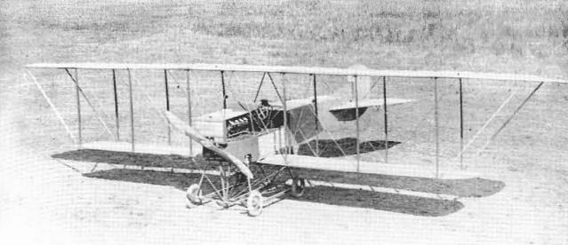
The second Curtiss Model G, built for the US Army in 1913, was a great Improvement over the first but was still not a notable success; Curtiss had no previous experience with tractor-type landplanes.
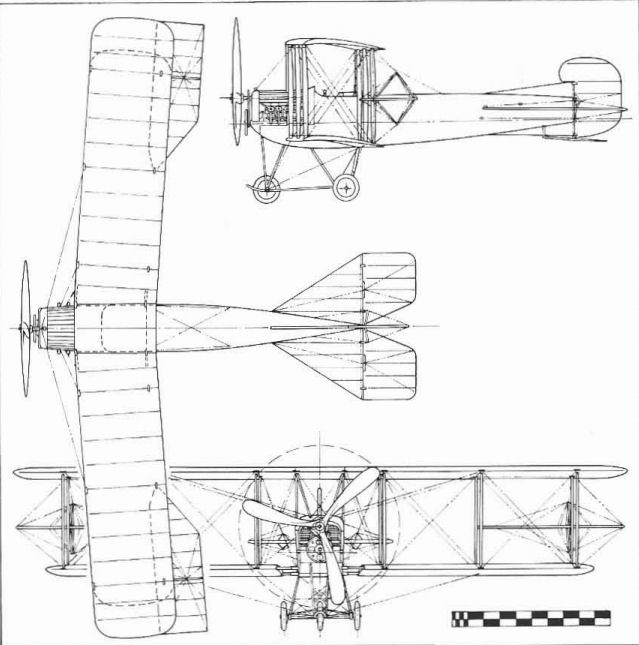
Model G No.S.C.21
Model BA (Models 13, 14)
The BA flying-boat was a logical development of the F and K models intended to replace the F as the standard US Navy trainer flying-boat in 1918. The unusual use of a third letter in the Curtiss designation, BAT and BAP, is apparently an afterthought intended to distinguish between two configurations of the same aeroplane.
The final form of the BA served as the prototype for the 1918 Model MF and the postwar Seagull series.
BAT (Model 13). In its original form, the BA used a 100 hp Curtiss OXX engine mounted as a tractor (T) in the style of the 1914 McCormick Boat and the two-man crew sat behind the wings. This arrangement was unsatisfactory and the aeroplane was converted to a pusher.
BAP (Model 14). With the engine now installed as a pusher (P) and the crew moved forward, the BA became a satisfactory design. A simplified hull and minor refinements in the production version resulted in the new designation of MF.
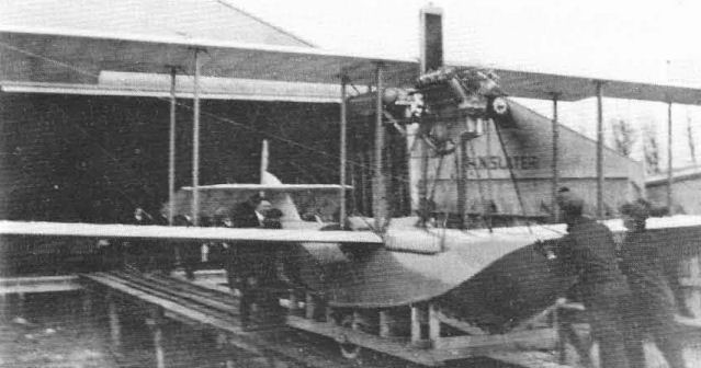
The Model BA was intended as a replacement for the F-Boat. The designation was changed to BAT to distinguish the tractor version from the later pusher (BAP) configuratIon.

The BAP was the pusher version of the BAT and became the prototype for the later Model MF.
Model H America. The Model H twin-engined flying-boat originated at the request of Rodman Wanamaker, wealthy owner of department stores in New York and Philadelphia, who sought to win the ?10,000 (then 50,000 US dollars) prize offered by the British newspaper The Daily Mail for the first aerial crossing of the Atlantic Ocean. The Curtiss organization was the logical one to develop the required aeroplane, which the patriotic Mr Wanamaker had already named America, and an order for two machines was placed in August 1913.
In form, the Model H followed the layout of previous Curtiss flying-boats, but it was enlarged in order to carry the fuel needed for a flight of 1,100 miles, the longest leg of the proposed transatlantic flight, and had two 90 hp Curtiss OX engines mounted as pushers. To increase their comfort, the two pilots and the mechanic were seated in an enclosed cabin. The wings, with two bays of struts on each outer panel, had tapered ailerons built into the upper wing, which also had a large overhang. The wings, which became the pattern for subsequent multi-engined flying-boats and their British-built counterparts for the coming war years, were designed by B. Douglas Thomas. Thomas was assisted to a considerable degree by another Briton, Lt John C. Porte, then on leave from the Royal Navy, who was selected by Wanamaker to pilot the America.
Since the Wright patent suit was active at the time, Curtiss sought to avoid duplicating certain details of the Wright system. The ailerons were hooked up so that only one worked at a time, one being pulled down by the action of the pilot's foot instead of both being moved in opposite directions by a control wheel. The wheel control was used to operate the rudder.
Following naming ceremonies on 22 June, 1914, the America began an extensive test programme. One of the early troubles was the tendency of the bow to submerge as power was applied to the engines. The high thrust-line of the engines applying forward force and the water drag on the hull acting in the opposite direction created a downward force on the bow. This phenomenon had not been significant in the past because of the relatively low power available in the smaller single-engined flying-boats.
The need for more forward buoyancy in the hull was met first by adding planing surfaces to the sides of the hull forward of the step. These were soon replaced by additional structures that Curtiss called 'fins' attached to each side of the hull, above the chines, that increased the volume and buoyancy of the hull as well as adding planing area. This Curtiss-developed feature was to be used on many other flying-boats into the 1930s but were called sponsons rather than fins.
With its take off problems solved, the America still could not carry the required fuel load for the distance, and the lifting capacity was then increased by adding a third engine to the top of the wing in a tractor position.
With the America finally considered to be ready, the oft-postponed flight was scheduled for 5 August, 1914, with Lt Porte as pilot. The starting point was to be St John's, Newfoundland, with intermediate stops at Fayal and San Miguel in the Azores and on to Portugal. Crews had actually been dispatched to some of these points when the flight was cancelled by the outbreak of what was to become the Great War, or World War 1 to later historians.
Lt Porte was recalled to duty in the United Kingdom and was able to persuade the Admiralty to purchase the America and its sister ship. These were to become the prototypes of a long line of twin-engined biplane flying-boats that would serve Britain and the US Navy well into World War II. The original America, in fact, gave its name to the class, and later developments up to H-16 sold to Britain became known as Small Americas and Large Americas.
Model H America
Three crew.
Span 74 ft (22,55 m) upper, 46 ft (14 m) lower; length 37 ft 6 in (11,43 m); height 16 ft (4,87 m).
Empty weight 3,000 lb (1,360 kg); gross weight 5,000 lb (2,268 kg).
Maximum speed 65 mph (104,6 km/h); range 1,100 miles (1,770 km).
Powerplant two 90 hp Curtiss OX.
RNAS serial numbers: 950, 951 (Curtiss prototypes), 1228/1235 (8, Aircraft Manufacturing Co, UK), 1236/1239 (4, Curtiss), 3545/3594 (50, Curtiss).
Model H Series (Model 6)
The Curtiss twin-engined flying-boat line that started with the America in 1914 continued into 1918 with designations in the H-series up to H-16. Only seven of the designations from H to H-16 are known to have been carried by existing aircraft. In the 1935 system, Model 6 applied to H-4, 6, 7,8, and 10, but details are not available.
Until the introduction of the H-12, the only customer was Britain's Royal Naval Air Service. Curtiss's lead in large flying-boat development was a notable exception to the state of American aviation in the 1915-17 period, when European designs made great advances under the stimulation of war requirements while America, isolated from these developments, fell farther and farther behind.
Even so, the design of the Curtiss hulls demonstrated notable structural and hydrodynamic deficiencies in British wartime service. Late in 1915, Lt Porte, now back in uniform, designed and built improved hulls and fitted them with standard Curtiss wings and tails. The improvements proved desirable, and the F-series of large flying-boats was produced with the new hulls and British-built Curtiss wings to become the standard patrol/bomber flying-boat of the RNAS and the later Royal Air Force. The final F-5 model was to be built in the United States by Curtiss in 1918 in parallel with Curtiss's own Model H-16.
H-4 (Model 6) - The designation H-4 was assigned to the original America after modification in Britain. Subsequent production versions were identified in RNAS service as the Small Americas. As built by Curtiss, the powerplants were two 90 hp Curtiss OX installed as tractors. These were not favoured by the RNAS, which substituted ten-cylinder 100 hp French Anzani air-cooled radial engines or two 130 hp British Clerget rotary engines for the water-cooled Curtiss types.
Curtiss built sixty-two H-4s including the prototypes and another eight were built in the United Kingdom by the Aircraft Manufacturing Company (Airco) and Saunders.
RNAS serial numbers: 882, 883, 950, 951,1232/1239 (Built by Aircraft Manufacturing Company and Saunders),3454/3594.
H-8 - No data available other than published photographs that show it to be a twin pusher slightly smaller than the America and powered with the same Curtiss OX engines.
H-14 - The H-14 was a smaller twin-engined flying-boat than the H-12 and reverted to the pusher engine arrangement of the original America. The US Army ordered sixteen examples, serial numbers 396/411, before the prototype was completed late in 1916. This did not come up to expectations and work on the Army machines was halted.
In mid-1917, the prototype was converted to a single-engined type with 200 hp Curtiss V-X-3 engine and was redesignated HS-1 (H-model with single engine). The Army having cancelled its order, the sixteen former H-14s were completed for the Navy in the HS-1 configuration and delivered with Navy serial numbers A800/A815 and new Liberty engines that resulted in the designation HS-1L.
H-14
Powerplant two 100 hp Curtiss OXX-2.
Span 55 ft 9 5/32 in (16,99 m)(upper), 45 ft 9 5/32 in (13,94 m) (lower); length 38 ft 6 5/8 in (11,75 m); wing area 576 sq ft (53,51 sq m).
Empty weight 3,130 lb (1,420 kg); gross weight 4,230 lb (1,919 kg).
Maximum speed 65 mph (104,6 km/h); climb 2,000 ft (610 m) in 10 min.
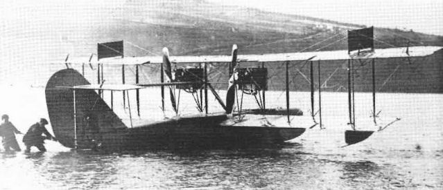
The. H-14 was a small twin-engined flying-boat that was converted to a single-engined type with a more powerful engine. The example in this photograph has also been identified as the H-8.
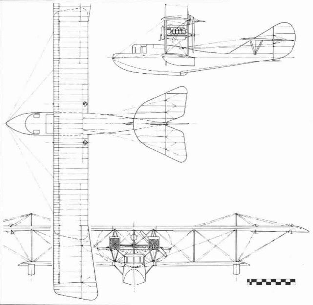
Model H, America
Model J. The Model J tractor was the first aeroplane designed for Curtiss by his imported British engineer, B. Douglas Thomas, and logically bore a great resemblance to the established British Sopwith and Avro tractor designs.
Two Js were built and demonstrated desirable characteristics from the start. The 90 hp Curtiss O engine fitted behind a new nose radiator and the crew sat in tandem cockpits equipped with shoulder-yoke aileron controls. The ailerons were built into all four panels of the original equal-span wings, which used a modified French Eiffel 36 aerofoil. In an attempt to avoid infringement of the Wright patent, the ailerons of the Model J operated independently and moved only upward from the neutral position.
Flown in the spring of 1914, the first J was tried both as a landplane and a single-float seaplane. The upper wing span was soon extended to help carry the added weight of the float and the lower wing ailerons were removed. The longer wings were retained when the US Army bought both Js for $6,725 each and assigned them Army serial numbers 29 and 30.
The key features of the Model J were combined with the Model to create the immortal JN design described later.
Model J
Two seats.
Span 40 ft 2 in (12,24 m); length 26 ft 4 in (8,02 m); wing area 340 sq ft (31,58 sq m).
Empty weight 1,075 lb (487,6 kg); gross weight 1,635 lb (741,6 kg).
Maximum speed 70 mph (112,65 km/h); climb 3,000 ft (914 m) in 10 min; endurance 4 hr.
Powerplant 90 hp Curtiss OX.
US Army serial numbers: 29, 30.
The Jenny
The Curtiss Jenny, to apply the popular name to the entire production JN series, was a design that achieved immortality through circumstances rather than by the normal criteria of competitive performance or a spectacular combat record.
The long production life of this model, its step-by-step evolution, its status as the principal American and Canadian primary trainer of World War I, and its unique position in the early postwar years of American civil aviation justify the devotion of a separate section of this book to this particular design.
The JN series began with the merging of the better features of the J and N models of 1914 into a new design. The name Jenny was an entirely logical phonetic corruption of the model designation JN. By coincidence, it was also a name eminently suited to that particular aeroplane. As with boats, aeroplanes are regarded by their crews as having feminine characteristics and Jenny was exactly right for the personality of the aeroplane.
The N series continued to develop separately but the Model J was dropped in favor of the JN. There was no officially designated JN or JN-1 model. The first JNs were ordered by the US Army late in 1914 as Service observation types; however, their successors were trainers. It has been said that over 95 per cent of the US and Canadian pilots trained during World War I flew a JN in some phase of their training. The JN-4 series became Model 1 in the 1935 designation system starting with the JN-4A.
JN-2 - Eight modified Js were ordered by the Army in December 1914. Since Curtiss considered these as having significant features of the model N, the type was eventually designated JN-2. Deliveries to the First Aero Squadron began in April 1915. The JN-2s moved with the squadron from San Diego to Fort Sill, Oklahoma, and then to the Mexican border, where early in 1916 they became the first US Army aeroplanes used in tactical operations.
The JN-2s had equal-span wings with the Eiffel 36 aerofoil and four strut-connected ailerons with shoulder-yoke control. Performance was poor and drew criticism from all levels of the Army. Curtiss improved matters somewhat in late 1915 by progressively updating the six survivors with JN-3 wings and then 100 hp OXX engines. In spite of certain obvious differences, the refurbished JN-2s were thereafter regarded as JN-3s.
US Army serial numbers: 41/48
JN-3 - The JN-3s were evolutionary improvements of the JN-2 and featured a return to the unequal-span wings of the original modified J with upper-wing ailerons only. The control system was improved by a change to Deperdussin control featuring a wheel for aileron control and a foot bar for the rudder.
Britain bought 91 JN-3s starting in March 1915 and the US Army bought two in August. To expedite production for Britain, Curtiss established a branch factory in Toronto and twelve of the estimated 99 JN-3s were built there.
RNAS serial numbers: 1362/1367, 3345/3423 (Curtiss), 8392/8403 (Canada)
US Army serial numbers: 52, 53
Production Model Ns (Models 1D, 5)
The expansion of US aerial forces in 1915-16 resulted in later versions of the Model N being produced independently of the JN series. Models designated N-1 to N-7 are not known to have been built; the known production models are the N-8 and -9 described below.
N-8 (Model 1D) - In April 1915, the Army bought four N-8s (serial numbers 60/63) that were essentially duplicates of the contemporary JN-3 except for the 90 hp OX-2 engine, RAF 6 aero foil, and retention of the shoulder-yoke aileron control. The first one had the wing span increased 10 ft (3 m) for better altitude capability by using a longer-span centre section and two 5 ft (1,52 m) extra sections for the lower wings inboard of standard-size outer panels. The increased span was soon deleted.
The N-8s were assigned to the Mexican Punitive Expedition of 1916 but were not operated over Mexican territory before being transferred to training duties.
N-8 (standard wing)
Observation aircraft. Pilot and observer. 90 hp Curtiss OX-2.
Span 43 ft (13,1 m); length 27 ft (8,22 m); wing area 350 sq ft (32,5 sq m).
Empty weight 1,335 lb (606 kg): gross weight 1,932 lb (876 kg).
Maximum speed 70 mph (112,65 km/h): endurance 4 1/2 hr at cruising speed.
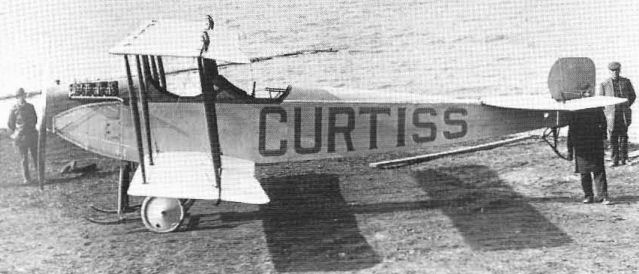
The first successful Curtiss tractor, the Model J of early 1914, was designed by B. Douglas Thomas, an experienced designer imported by Curtiss for that particular purpose.
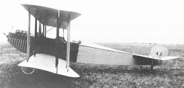
The first aeroplane with a J designation was the JN-2 of 1915. The US Army bought eight with the equal-span two-aileron wings shown. The shoulder yoke for aileron control can be seen in the rear cockpit.
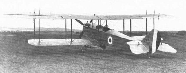
A JN-3 used by the Royal Naval Air Service in 1915-16. The four-blade propeller was not standard.
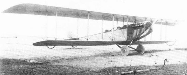
The N-8 was developed for the US Army. This is the prototype with its original long-span wings which were later removed.
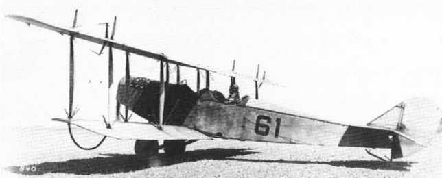
The second N-8, with standard two-bay wings. The number 61 on the fuselage is the US Army serial; no national markings were in use at the time.
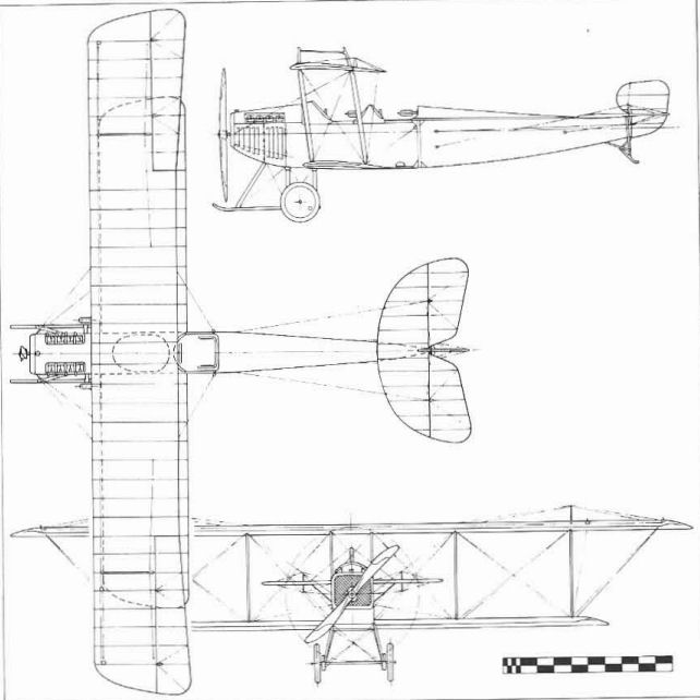
Final Model J.
Model M (Morris) Flying-boat. It is not known whether the M designation identifies the 1913 monoplane flying-boat built for Raymond V. Morris in the Curtiss letter designation system or is M-for-Morris; the 'boat, which predates both the J and N models, was referred to mostly as 'The Morris Boat'.
The high and swept-back wing was fitted to a narrow single-seat hull covered with mahogany veneer in the manner of later F-boats and the 90 hp pusher engine was carried at the level of the wing. The stabilizing floats were carried on the ends of trusses that also formed the wing bracing.
Morris took the M-boat with him to San Diego when he became Curtiss's manager there. Its performance as a monoplane was unsatisfactory so a lower wing was added at San Diego.
Monoplane specification:
Single-seat.
Span 34 ft (10.36 m); length 25 ft (7.62 m); height 10 ft 10 in (3.3 m); wing area 120 sq ft (11.14 sq m).
Powerplant 90 hp Curtiss O.
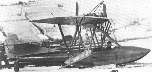
This single-seat Model M was built in 1913 for Raymond V. Morris, a Curtiss employee, to use in his work.
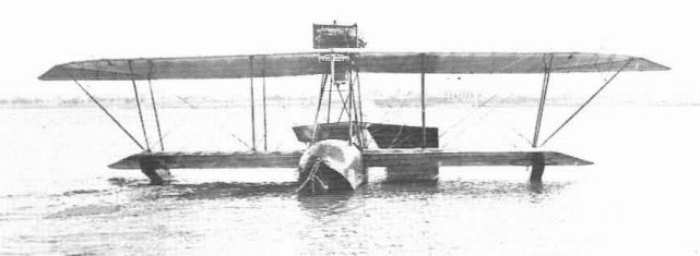
The performance of the Model M as a monoplane was marginal so it was converted to a biplane in Curtiss's San Diego shops.
While producing the standard F-boat for the open market, Curtiss also built custom-designed 'boats to special order. These were usually named to the preferences of their owner rather than being given Curtiss designation.
McCormick Boat. In 1914, Curtiss delivered a special five-seat tractor flying-boat to Harold F. McCormick, who used it for business and to commute from his Lake Michigan home to his Chicago office, a trip of 28 miles (45 km).
The McCormick 'boat was considerably larger than the F, with the cockpit behind the wing and the engine ahead of it as on the 1911 tractor hydro. McCormick's 'boat was eventually rebuilt to put the cockpit and powerplant in the standard F-boat arrangement.
Original specifications:
Span 38 ft 4 in (11.68 m); span across ailerons 41 ft 8 in (12.69 m); length 24 ft (7.31 m).
Powerplant 100 hp Curtiss OXX.
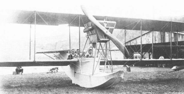
Thc Curtiss McCormick flying-boat of 1914 was built as a tractor but was soon modified to have the engine at the rear and the pilots and passengers ahead of the wings.
Model N. The Model N was a parallel design to the Model J of 1914, differing from it mainly in the use of an RAF 6 aerofoil instead of the Eiffel 36. In 1915, the best features of the J and N models were combined to produce the JN.
The original Model N was a two-seat biplane with equal-span two-bay wings and a 100 hp Curtiss OXX engine in the nose. The nose radiator duplicated the J installation but the N's ailerons were between the wings. The Curtiss shoulder-yoke aileron control system was used. The prototype N was evaluated by the US Army at North Island, was accepted at a price of $7.500, and given Army serial number 35.
During its Army trials, Curtiss repossessed the model at North Island to further his defence of the Wright patent suit. He locked the ailerons and rigged in the exceptionally high dihedral angle of seven degrees to prove that full three-axis control was not essential to safe flight.
After a period of service in the original configuration, its wings were modified to incorporate the ailerons in the upper wing.
The Model N was later rebuilt in Curtiss shops on North Island to a side-by-side two-seater and filled with a 90 hp British Beardmore engine. The greater weight of the new engine in a longer nose just compensated for the balance change of moving the former front-seat occupant aft.
Model N
Two seats.
Span 41 ft 6 in (12,64 m); length 27 ft 2 in (8,28 m); wing area 371 sq ft (34,46 sq m).
Empty weight 1,300 lb (589,6 kg); gross weight 1,800 lb (816,46 kg).
Maximum speed 82 mph (131,96 km/h); climb 4,000 ft (1,220 m) in 10 min; endurance 4 hr.
Powerplant 100 hp Curtiss OXX.
US Army serial number: 35.
Model O. Not known to be an official Curtiss designation, but seen occasionally in reference to the rebuilt Model N with side-by-side seating and Daimler engine. It is logical that such extensive changes would justify a new designation.
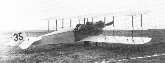
Also designed by Thomas, the Model N was identical to the J except for wing details.
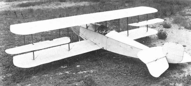
The Model O was either a new aeroplane or a redesignation of Model N when it was rebuilt as a side-by-side two·seater.
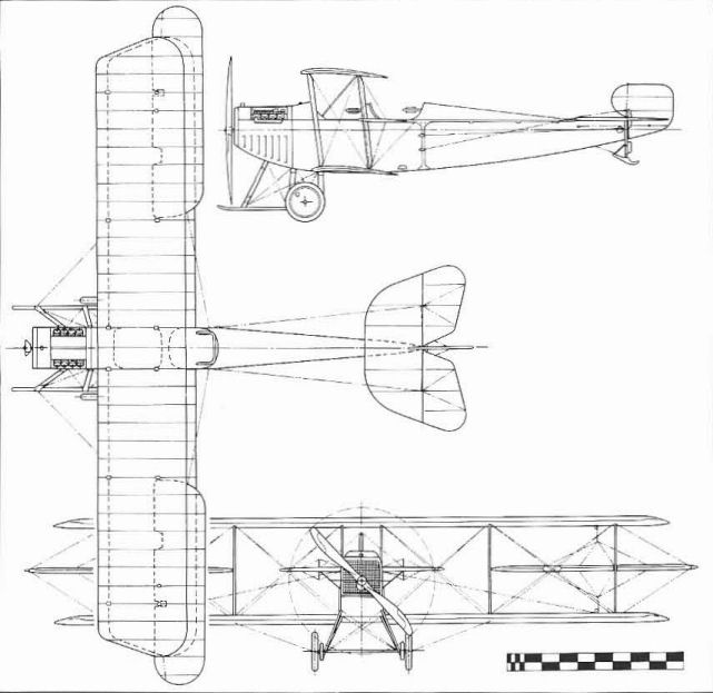
Model N.
Model C-1 Canada
The Canada of 1915 was the first twin-engined Curtiss landplane designed as such. It was an adaptation, however, as the wings and 160 hp Curtiss V-X powerplant installation were similar to those of contemporary Curtiss flying-boats. The name resulted from the fact that design and construction of this large aeroplane were entrusted to the new Curtiss plant in Toronto. The official designation was C-1.
Design work began in May 1915, and the prototype was completed in July. The early flights were made with Curtiss OX engines because the desired V-X models were not then available. Unconventional features or the three-seat Canada were the short fuselage, with the tail surfaces carried on booms, and the tandem-wheel-pair arrangement of each undercarriage unit.
The Canada showed great promise, and 102 were ordered by the RNAS. However, all but one were cancelled. The prototype was delivered to the United Kingdom in November and received RNAS serial 3700. Eleven others were built but their disposition is unknown. The prototype was based at Farnborough, where it was modified and used for test work. The wing overhang was now braced with struts instead of the original wires and the C-1 was the first aeroplane to fly with the new streamlined interplane wires (actually tie-rods), developed by the Royal Aircraft Factory, that came to be known as RAF Wires.
Span 75 ft 10 in (23,11 m)(upper), 48 ft (14,63 m)(lower); length 33 ft 4 3/4 in (10,17 m); height 15 ft 6 in (4,72 m).
Empty weight 4,700 lb (2,132 kg); gross weight 6,300 lb (2,858 kg).
Maximum speed 90 mph (144,83 km/h); range 600 miles (965 km).

The Curtiss C-1 Canada was built in Canada and America flying-boat wings were adapted for the landplane bomber. Struts bracing the upper wing overhang were added in Britain.
H-10 - A twin-engined flying-boat larger than the H-8 and having the Curtiss OX engines installed as tractors. On the H-10, two booms were used to connect the engine nacelles to the horizontal tail.
Model R Series (Model 2)
Following Curtiss's acquisition of designers experienced with tractor-type aeroplanes, the company sought to develop larger and more advanced models than the J and N for military use. The first such effort was the two-seat Model R, a tandem two-seater introduced early in 1915 and powered with the new 160 hp Curtiss V-X engine that was essentially an enlargement of the well established O and OX models. The Model R was not notably successful but, thanks to having no significant competition, enjoyed brisk sales to both the US Army and Navy from 1915 until the end of the war and remained in Navy service into 1926. Early models were also bought by Britain's Royal Flying Corps.
R - The prototype R could be regarded as an enlarged version of the original Model N, with equal-span wings, RAF 6 aerofoil, no dihedral, and shoulder-type aileron control. The most noticeable differences, other than the size, were the extremely heavy stagger of the wings and the use of a single long cockpit for both occupants. Although heavier than the N, the R was still light enough for its balance to be affected by crew location, so the pilot occupied the rear seat. The presence or absence of the observer in the front cockpit, located on the centre of gravity, did not affect the balance of the aeroplane. The single company-owned prototype was soon modified by the addition of dihedral and tested both as a land plane and as a single-float seaplane.
R-2A - The R-2A was a parallel development with the R-2 but was completed first. Again, the crew was in two separate cockpits and the tail and landing gear were redesigned, but the wings were equal-span and retained the interplane ailerons and no-dihedral rigging. In August 1915, Curtiss pilot Raymond V. Morris overloaded the R-2A and set an American altitude record of 8,105 ft (2,470 m) for pilot and three passengers.
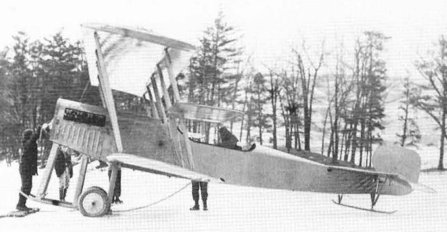
One ol the latest Curtiss military tractor biplanes with a 160 h.p. Curtiss engine. The prototype Model R was essentially an enlarged and more powerful Model N. It had a single cockpit with two seats in tandem.

The Model R was also tested as a single-float seaplane.
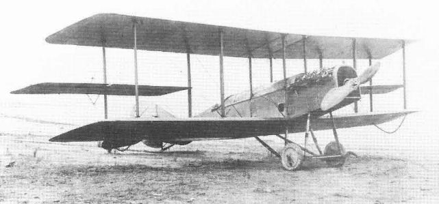
The R-2A was an improved R with two separate cockpits. The front cockpit, beneath the upper wing, is seen covered.
R-2 - The R-2 model that appeared late in 1915, was an extensive refinement of the original Model R, The crew was now accommodated in two separate and widely-spaced cockpits, the tail was redesigned to use a fixed vertical fin and unbalanced rudder, and the undercarriage was redesigned, The wings took on the appearance of the JN-3 and short-wing N-8 by having the upper wing span increased to 45 ft 11 1/2 in (14 m), having the ailerons in the upper wing, and dihedral. Experiments were conducted on one example fitted with a propeller spinner and dual radiators installed on the side of the fuselage, The production versions retained the nose radiator and had an enlarged vertical tail with balanced rudder that established the shape for subsequent R-models into 1918.
Twelve of the improved R-2s were sold to the US Army in 1916 for $12000 each and some saw service with the Mexican Punitive Expedition. One hundred others were sold to the RFC; the original Curtiss V-X engines were replaced by 200 hp Sunbeam Arab IIs,
US Army serial numbers: 64/75, RFC serial numbers 3445/3544,
R-2
Observation aircraft. Pilot and observer. 160 hp Curtiss V-X.
Span 45 ft 11 1/2 in (14 m) upper, 38 ft 4 7/8 in (11,7 m) lower; length 24 ft 4 3/8 in (7,42 m); wing area 504,88 sq ft (46,9 sq m).
Empty weight 1,822 lb (826 kg); gross weight 3,092 lb (1,402 kg).
Maximum speed 86 mph (138,4 km/h); climb 4,000 ft (1,219 m) in 10 min; endurance 6,7 hr at cruising speed.
R-4 - Fifty-three R-4s ordered by the Army in 1916 were improved versions of the Army R-2s using later 200 hp Curtiss V-2-3 engines. Two more were purchased in 1917. Except for a redesigned tailskid in a more forward position and strut-connected ailerons in both wings, the R-4s were hard to distinguish from the R-2s. Some R-4s also entered Mexico with Gen Pershing's Punitive Expedition. Additional Army R-4s were ordered after the US entered the war but most were cancelled to allow maximum delivery to the Navy.
US Army serial numbers: 177/192 (16), 218/316 (36), 469, 2157, 37932
R-4L - Late in 1917 several of the large single-engined aeroplanes on hand in the Army and Navy were used as test beds for the US Government's new twelve-cylinder Liberty engine. An Army R-4 was among these and, when it was found that the new engine improved the characteristics of the aeroplane, a number of other R-4s were fitted with the Liberty and redesignated R-4L (L for Liberty). Twelve production R-4Ls were then ordered. Principal recognition feature, other than the larger engine, was the enlarged nose radiator similar to that used on the famous de Havilland 4.
US Army serial numbers: 39362/39367 (6), 39954/39959 (6)
R-4LM - After the US Army started to fly the new US Air Mail on 15 May, 1918, a need for aeroplanes with greater load capacity than the JN-4Hs then being used became apparent. At Army request, Curtiss converted six R-4Ls to R-4LM by adapting the front cockpit to a mail compartment with a capacity of 400 lb (181 kg).
R-4
R-4 - Observation landplane. Pilot and observer. 200 hp Curtiss V-2-1
Span 48 ft 4 5/32 in (14,73 m); length 28 ft 11 3/4 in (8,83 m); height 13 ft 2 1/4 in (4,02 m): wing area 504,88 sq ft (46,9 sq m).
Empty weight 2,275 lb (1,032 kg): gross weight 3,242 lb (1,470 kg).
Maximum speed 90 mph (144,83 km/h); climb 4,000 ft (1,219 m) in 10 min.
R-4LM - Single-seat mailplane. 400 hp Liberty.
Span 48 ft 4 5/32 in (14,73 m); length 29 ft (8,83 m).
Maximum speed 120 mph (193,11 kmjh); range 350 miles (563 km).
R-7 - A long-wing landplane that appears to be a development of the R-3 because of similar strutting. Powerplant was the same 200 hp Curtiss V-2-3 used in the R-4. The designation appearing in contemporary publications was in quotation marks as though it were in doubt; Curtiss identified the machine only as 'New York Times' since the single example had been sold to that newspaper. Flown by Curtiss test pilot Victor Carlstrom, it attempted a nonstop flight from Chicago to New York City in November 1916. The flight ended just short of the half-way point due to a fuel leak but still set a new US nonstop record of 452 miles (727 km). This date puts the 'R-7' ahead of the military R-6 model chronologically.
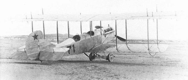
The R-2 had unequal span wings and integral ailerons. Number 71 is the US Army serial and the red star on the rudder was the earliest US Army aeroplane insignia.
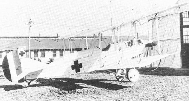
R-4s were improved R-2sand were in production from 1916 into 1918. This is a special white-painted ambulance conversion with covered litter behind the cockpit.

In 1918 a number of R-4s were re-engined with the Liberty to become R-4Ls and some others were built as such.
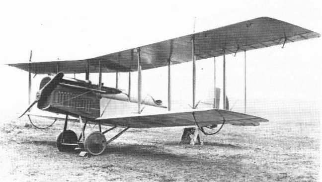
The six R-4LMs were R-4Ls converted-to single-seat mail planes for the Post Office.

R-7 Curtiss Chicago-New York machine is an unconfirmed designation applied to this special aeroplane built for the New York Times in 1916. Practically an R 4 with an extra bay added to each wing. Span, 60 feet. Engine, 160 h.p. Curtiss.
Model G (1916)
The Curtiss G designation is confusing, for it seems to have been applied to both the first Curtiss tractor model delivered to the Army in 1913 and to a nacelle-type pusher based on 1915-16 European practice and using existing Curtiss Model R wings and tail and the 150 hp Curtiss V-X engine. Curtiss photographs of this single 1916 model have been labelled both Model G and Pusher R, which see. Photographs indicate that the 1916 model originally had equal-span wings with interplane ailerons and that the upper wing was then extended and incorporated the ailerons.
Pusher R - In 1916 Curtiss made an attempt at reviving US Army interest in the landplane pusher configuration by filling a pod, containing tandem cockpits and a pusher engine, with early Model R wings and new vertical tail surfaces to create a pusher in the 1914-15 European style. Longer-span R-2 wings with inset ailerons were soon installed. While performance reportedly matched that of the contemporary R-models, there was no official support for the design. This model also appears in Curtiss records as a second Model G.
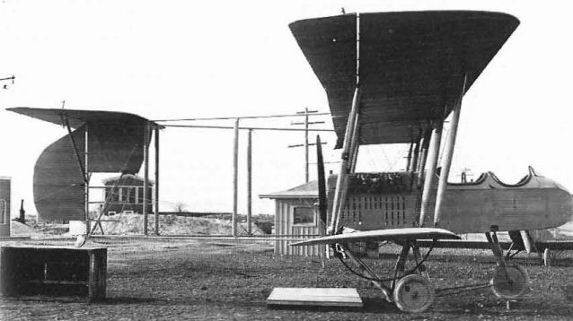
This 1916 pusher design has been identified as the Model G and has also been referred to as a Pusher R.
The Jenny
The Curtiss Jenny, to apply the popular name to the entire production JN series, was a design that achieved immortality through circumstances rather than by the normal criteria of competitive performance or a spectacular combat record.
The long production life of this model, its step-by-step evolution, its status as the principal American and Canadian primary trainer of World War I, and its unique position in the early postwar years of American civil aviation justify the devotion of a separate section of this book to this particular design.
The JN series began with the merging of the better features of the J and N models of 1914 into a new design. The name Jenny was an entirely logical phonetic corruption of the model designation JN. By coincidence, it was also a name eminently suited to that particular aeroplane. As with boats, aeroplanes are regarded by their crews as having feminine characteristics and Jenny was exactly right for the personality of the aeroplane.
The N series continued to develop separately but the Model J was dropped in favor of the JN. There was no officially designated JN or JN-1 model. The first JNs were ordered by the US Army late in 1914 as Service observation types; however, their successors were trainers. It has been said that over 95 per cent of the US and Canadian pilots trained during World War I flew a JN in some phase of their training. The JN-4 series became Model 1 in the 1935 designation system starting with the JN-4A.
With a good tractor trainer in production in America, it was logical for Britain to order the same model for its rapidly-expanding war training programme. The relatively large-scale production that followed naturally led to rapid step-by-step refinement of the basic design. By the time the United States entered World War I in April 1917, the Jenny had reached the JN-4D model. Thanks to increasing US and British military orders, plus sales to neutral nations and American private owners, the Curtiss JN-4 was built in greater numbers than any other American model up to the time the US entered the war. Increased demand from Britain resulted in the establishment of a Canadian subsidiary, Curtiss Aeroplane and Motors, Ltd, in Toronto. This plant built JN-3s for Britain prior to being taken over by the Canadian Government and being renamed Canadian Aeroplanes, Ltd. The Canadian-built JN-4s became known as Canucks to distinguish them from the American built Jennies.
When the build-up of American airpower began after the country entered the war, the JN-4 was the only proven domestic design ordered into immediate mass production. A total of 6,070 Jennies, JN-4 to JN-6H, was delivered to the US Army out of 7,166 ordered after April 1917. These orders were placed with Curtiss, which delivered 4,895, and with six other firms. While the US Navy acquired 134 Jennies during the war and others after, most of the Navy's were transferred from the Army and are presumed to be included in the Army figures.
The price of a Jenny dropped steadily as the production rate increased, but rose again when larger engines were installed. Also, costs were different for similar models built by different manufacturers in 1917-18. Direct cost comparisons between early and late models are invalid because the cost of the engines, instruments, and other government furnished equipment was not included in the contract price of Army aeroplanes ordered after the JN-4B.
The following JN-4 costs, taken from the Congressional Record, were established after the postwar investigation of aircraft procurement and the final settlement of the war contracts:
JN-4, 4A, 4B $8,160 (with engine, etc)
JN-4Can $4,250 (airframe only)
JN-4D $4,750
JN-4D-2 $3,500
JN-4H, 6H $4,750
Contrary to current belief, the era of the cheap war-surplus aeroplane did not begin right after the war. The Army and Navy did not put their surplus aircraft on the open market immediately; instead, considering the condition of some of the machines, the government invited bids for their purchase from the manufacturers and other responsible organizations with overhaul and repair facilities. Under this arrangement, Curtiss bought $20,000,000 worth of aeroplanes and engines, mostly Jennies and OX-5s, for $2,700,000, or approximately 13 cents in the dollar.
Starting in mid-1919, Curtiss launched an advertizing campaign that emphasized the skillful factory reconditioning or overhaul of these aircraft that made them safe for public use. Jennies advertized as brand-new were sold by Curtiss for $4,000 late in 1919 and new OX-5 engines were priced at $1,000. Prices quoted by other organizations selling the same items were comparable or slightly lower.
The first JNs available to the American public from sources other than Curtiss were Canadian JN-4 Canucks exported from Canada by two firms, one was John Ericson, designer of the Canuck and the other was a new sales organization established after the war by the leading Canadian war aces William A. Bishop and William G. Barker. Late 1919 prices for Canucks in as-new condition were $2,600-$3,000.
Curtiss prices dropped only slightly in mid-1920, following large-scale dumping efforts by firms disposing of British war surplus. Unused JN-4Ds were $3,250, rebuilds were $2,000 to $2,750, and Canucks reconditioned by Curtiss were $1,500. Rebuilt OX-5 engines were $750 and used OX-5 engines were $300 to $500 depending on condition. While the Jenny price was close to the original selling price, it was still relatively low compared to the only comparable postwar models then in production, the Curtiss Oriole at $8,000, down from $9,850, and the Laird Swallow at $6,500.
The day when an interested purchaser could go to a government warehouse and acquire a surplus Jenny for a few hundred dollars was still in the future and did not play a large part in the early postwar sales picture. Most of the surplus aeroplanes reached their first civilian operators through organizations that had bought in quantities with the intention of reselling. Toward the end of their days, Jennies were changing hands among the private owners for $500 to as little as $50.00. Unused OX-5s dropped to a standard price of $250 by 1928.
After the war, Jenny had two careers, one civil and one military. The military use resulted in additional designations being applied to existing aeroplanes, which are identified later in this section. The civil operations produced no new designations but did result in uses and configurations undreamed of by the original manufacturers. These two careers are described separately.
After the war the Army decided that the 90 hp Jennies were marginal even for primary training and quickly withdrew them from those military schools that were still in operation. The higher-powered JN-4H and JN-6H models with 150 hp American-built Hispano-Suiza engines were retained and few of these reached civil owners. Some 216 were transferred to or purchased by the Navy in the years 1920-23.
The Hisso Jennies remained the Army's principal primary trainer until new designs began to enter the inventory in 1925. Because funds were limited for new equipment but were available for maintenance and reconditioning, many JN-4H and 6H models were put through rebuilding programmes, conducted mainly at Army Air Depots that gave them the status of new aircraft even to the extent of sometimes receiving new Army serial numbers.
Basic differences between JN-4H and JN-6H models were eliminated during these programmes, from which they emerged with the new designation of JNS. This modification and rebuilding continued to the end of 1925, when the JNSs still formed the backbone of the National Guard Aviation Programme. The last US Army Jennies were withdrawn from service and scrapped in September 1927.
Jennies in the US Army inventory dropped from 3,285 in 1919 to 37 in 1927, their last year of service. The Navy, which had 76 in November 1919, ended 1926 with 22 examples on hand.
The most memorable reputation of the Jenny was earned at the hands of civil pilots in the years 1920-26. This was the Barnstorming period of American aviation. Former military pilots, as well as some who had learned to fly after the war, bought surplus trainers by the hundreds and set out through the country to earn money by carrying passengers, putting on aerial circuses and doing other work. Since the Jenny was the most plentiful of several similar surplus models available, this period has since been referred to as The Jenny Era. Certainly the first aeroplane that a large segment of the American public ever saw, or got close to, was a Curtiss Jenny. The term Barnstorming resulted from the close parallel between these gypsy fliers, moving from pasture to pasture in search of customers, and the old travelling theatrical troupes that held their performances in suitable barns along their route.
The Jenny, along with the similar Standard J-1, was the world's best stage for the wing-walker's act. It had a handy maze of struts, a straight-across axle between the wheels, wingtip skid bows, low airspeed, and most important, king-posts on top of the upper wing. Without these posts, moving from one aeroplane to another and most above-the-wing performances would have been impossible.
While systems of aircraft registration and airworthiness requirements were adopted by most aviation user nations in 1919, the United States did not sign the agreement. Consequently, there was no required licensing or inspection of American aircraft or pilots until 1927. Pilots who had just soloed could and did carry passengers for hire on their next flight, and in machines so decrepit that they well deserved the appellation of Crate that was frequently applied to them.
The owners had an absolutely free hand in the matter of structural modification, too, and many weird adulterations of the Jenny were to be seen. A popular one was the fitting of upper wing panels in place of the short-span lowers. This had its practical aspects; the attrition rate of lower wings in cow-pasture operations was considerable and sometimes caused local spares shortages. It was easy to reverse the strut fittings on an upper wing, add a set of struts to replace the overhang wires, and have a long-wing Jenny.
Recognizing the fact that most of the drag of the Jenny was in the wings, several small firms developed replacement wings in the early 1920s. Some of these were biplane sets that attached to the original fittings while using deeper-section aerofoils and fewer struts while others were parasol monoplane wings that were of necessity attached a little aft of the original upper wing position. Some owners took a course opposite to the Long Wing and clipped the overhang from the upper wing.
The Jenny Era began to wane in 1925, when efficient new production designs were finally able to get a foothold in the market that had long been dominated by the cheap war surplus types. The final blow was administered by the adoption of Federal licensing requirements for both aeroplanes and pilots at the beginning of 1927. The Jennies could not meet the new airworthiness requirements. Some did qualify individually for C licences while others continued to operate as unlicensed but legally registered aircraft. As the various States fell in line with the Federal regulations, the horizons of the Jenny became more and more limited until by 1930 it was downright illegal in almost every part of the country.
A handful pursued legal careers after that date in Hollywood, when they performed in period aviation films. Some of these were extensively modified to look like other models that were not available for film work.
The birth of the antique or vintage aeroplane movement in the 1950s led to a renewed life for the few surviving Jennies that were not in museums or still in the Hollywood Squadron. Four were known to be airworthy in 1976, more than half a century after the peak of Jenny production. Even though they are in far better condition now than when they were new, they are not used in the old Jenny role of trainer or sporting aeroplane; they operate under experimental licences primarily for exhibition purposes.
Starting with the JN-2, the Jennies are presented here in ascending order of JN designation concluding with the Twin JN and the JNS. Since performance of models with the OX engines is so similar, the technical data table for the JN-4D is representative of all.
<...>
JN-4 - The JN-4, virtually identical to the JN-3, appeared in July 1916. While some were used by the US Army for observation, most became trainers. Britain acquired approximately 105 JN-4s; others were sold to private owners and some equipped the Curtiss flying schools. At unit prices of $7,750, the US Army bought a total of 21 JN-4s on six contracts prior to US entry into the war in April 1917.
US Army serial numbers: 76/81, 120/125, 130/135, 318/319, 468, 2265, 2266, plus one unknown
RNAS serial numbers: 3424/3444, 8802/8880, 8901, N5670/5673
British records show a total of 160 mixed JN-3, JN-4 and JN-4A, transferred from the Royal Naval Air Service to the Royal Flying Corps. These got new RFC serial numbers as follows:
JN-3/JN-4 5404/5408, 5624/5639, 5722/5728, 5910/5915, 6121/6124, 7310, A614/625, A898/903, A1254/1260, A5160/5168, A5215/5224, A5492/5524
JN-4 A3276/3280
JN-4/JN-4A A5492/5496, B1910/1950
JN-4A A4056/4060
JN-4A (Model 1) - The JN-4A of November 1916 was a major refinement of the JNA initiated at British request that crystallized the Jenny configuration. Prominent external changes were new and enlarged tail surfaces, revised fuselage lines, six degrees downthrust for the OX-5 engine, four degrees dihedral for the wings instead of one, ailerons on both wings, and the trailing edge of the upper wing centre-section cut away to the rear spar. Two JN-4As (1262 and 1527) were fitted with 100hp Hall-ScottA-7A engines as prototypes for a re-engined series.
An estimated 87 JN-4As were built by Canadian Aeroplanes as part of US Army and British JN-4 contracts. Six hundred and one of the 781-unit JN-4A total went to the US Army for $4,753,874. The Navy acquired five.
Known US Army serial numbers: 1057/1656 (600),3925
Known Canadian serial numbers: C501/560 (60), C1015/1051 (37)
Known RNAS serial numbers: 8802/8901 (100)
Known RFC serial numbers: A4056/4060 (5)
US Navy serial numbers: A388, A389, A995/997 (5)
JN-4B (Model 1A) - The JN-4B was actually an earlier design than the JN-4A and introduced the revised fuselage and tail of the JN-4A. It had a level OX-2 engine, ailerons on upper wings only, and an uncut centre section. Introduced late in 1916, the JN-4B enjoyed brisk sales to civilians, and 76 went to the US Army for $8,000 each, including engine, propeller, and military equipment. Subsequent purchases were for airframes only, the government buying the engines, etc, separately. The US Navy acquired three direct from the factory and an additional six late in 1917 from the Curtiss Exhibition Company.
US Army serials: 141/176(36),229/264 (36), plus four in the 541/556 range.
US Navy serials: A157/159 (3), A4112/4117 (6)
JN-4C - Only two JN-4Cs were built as such by Curtiss. These were JN-4B airframes fitted with experimental wings using the RAF 6 aerofoil of the N-series in place of the JN's Eiffel 36. Both of these, fitted with Curtiss OXX-3 dual-ignition engines, went to the US Army in June 1917.
US Army serials: 471, 472
JN-4Can (Canuck) - The Canadian JN-4 evolved from the Canadian-built JN-3 independently of the Curtiss-built JN-4. Britain wanted more Canadian Curtiss trainers but was dissatisfied with certain features of the JN-3. The requested changes were made by F. G. Ericson, Chief Engineer of the newly-designated Canadian Aeroplanes Ltd, and the improved model, which flew in January 1917, was designated JN-4. Noticeable differences were a revised metal-frame empennage, strut-connected ailerons on both wings, and the use of stick for control instead of the JN-3's Deperdussin system.
Canadian JN-4 production was divided between Canada and the US Army, which acquired 680. Approximately 50 were transferred to the US Army from the winter flying schools that Canada had established in Texas in 1917. Some of these subsequently flew with a mixture of US and Canadian markings.
Because of their Canadian origin and certain structural and control system differences from the American built models, these were given the designation JN-4 (Can) when purchased by the US Army. In paperwork this was often (and incorrectly) shortened to JN-4C. However, the pilots and mechanics promptly named them Canucks and the distinction was retained by civil pilots in the postwar years.
The exact number of Canadian-built JN-4s is unknown because some unfinished Curtiss-built JN-4As were completed in Toronto and some Canadian wings were fitted to JN-4A fuselages in Canada. The accepted figure is 1,260 JN-4 aeroplanes delivered as such, to which should be added 87 JN-4As for a total of 1,347. The spare parts produced would raise the total to the equivalent of 1,611 complete aeroplanes.
A few Canucks remained in Canadian Air Force service into 1924 and surplus models served Canadian civil aviation into the 1930s. John Ericson sold approximately 120 reconditioned or assembled from spares up to 1927 and adapted some to three-seat Ericson Special Threes. Bishop-Barker sold approximately 42 Canucks and Hoffa Brothers of Vancouver converted a number to single-float seaplanes.
Canadian military serial numbers assigned to Canucks are: C-101/500 (400)***, C-501/1450* (950)***, C-1451-1500** (7)
* C-501/550 (50), C-1015/1051 (37) are reported as JN-4A
** C-1457 is highest number known to be built
*** 280 random numbers lo US Army
US Army serial numbers: 38533/38632 (100), 39062/39361 (300)
JN-4D (Model 1C) - The JN-4D was introduced in June 1917 and combined the stick control of the Canadian JN-4 with the lines and downthrust of the JN-4A. The prototype had ailerons on both wings but the production models had them on the upper wing only. A distinctive feature was the curved cut-outs of the inner trailing edges of all four wing panels.
Deliveries of 2,812 JN-4Ds to the US Army began in November 1917 and continued to January 1919. Surplus JN-4Ds were the principal JN-4 models that established The Jenny Era.
While some Army JN-4Ds were adapted to gunnery and bombing trainers, no designation changes were involved; the only designated JN-4D subtype was the JN-4D-2.
Since Curtiss could not fill the demand, Army contracts for JN-4Ds were given to six additional manufacturers, including the already-producing Canadian Aeroplanes, which delivered some JN-4Cans on JN-4D contracts. The following table shows orders, actual deliveries, and costs, and identifies the variously-built JN-4Ds by serial number.
JN-4D
Primary trainer. Two pilots. 90 hp Curtiss OX-5.
Span 43 ft 7 3/8 in (13,29 m); length 27 ft 4 in (8,33 m); height 9 ft 10 5/8 in (3,01 m); wing area 352 sq ft (32,7 sq m).
Empty weight 1,390 lb (630,49 kg); gross weight 1,920 lb (870,89 kg).
Maximum speed 75 mph (120,69 km/h); cruising speed 60 mph (96,55 km/h); climb to 2,000 ft (610 m) 7,5 min; service ceiling 6,500 ft (1,981 m).
JN-4D Production
Manufacturer Ordered Delivered Total cost Army serial numbers
Curtiss Aeroplane & 1,400 1,400 $4,417,337 2525/3924
Motor Corp 3 3 27,653 Navy A995/A997
1 1 - 12876
400* 1 4,015 47816
Fowler Airplane Corp, 50 50 $323,166 2405/2454
San Francisco
Liberty Iron Works, 100 100 $450,206 3976/4075
Sacramento 100 100 400,385 47415/47514
100 0 151,775
Springfield Aircraft Co. 400 400 $1,981,736 4976/5375
Springfield 275 185 1,086,402 44257/44531
300 0
St Louis Aircraft Co. 450 450 $2,137,500 33775/34224
St Louis 200 0
US Aircraft Corp, 50 50 $326,170 39868/39917
Redwood City
Howell & Lesser Co, 75 75 $300,000 47340/47414
San Franciseo 100 0 94,121
* JN-4D-2
JN-4D-2 - At Army request, Curtiss made many minor structural and control system improvements on the JN-4D. The only noticeable outward change was elimination of the engine down-thrust. The first JN-4D-2, US Army serial number 47816, was delivered to Dayton for Army test in September 1918. Previously, orders totalling 1,100 production aircraft had been placed with the five firms then building JN-4Ds and were to follow them. All were cancelled at the Armistice before any but the first Curtiss example were built.
Curtiss marketed a few civil JN-4D-2s immediately after the war but ended production when the new Oriole became available early in 1919.
JN-4H (Model 1E) - As a wartime production expedient, the US Army decided to re-engine the JN-4D with a more powerful engine to make it an advanced trainer rather than develop entirely new models and then build new factories for their production.
The adaptation was easy for Curtiss, and the improved model was designated JN-4H, the suffix letter indicating the 150 hp Wright-built Hispano-Suiza engine instead of sequential sub-type development. Structural strengthening was undertaken, the fuel capacity was increased from 21 to 31 US gallons (79,5 to 117,3 litres), and a larger nose radiator resembling that of the N-9C was installed. Fuel capacity was increased further on some by converting the upper wing centre-section to an auxiliary tank. The delivery of 929 JN-4Hs to the Army, all built by Curtiss, began in January 1918 and continued until the Armistice. Special-purpose variants were as follows:
JN-4HT - Four hundred and two of the JN-4Hs were delivered as dual-control JN-4HT, but this proper designation was not normally used. The Navy acquired 203 from the War Department between 1918 and 1923.
US Army serial numbers: 37933/38332, plus two from 42122/42125
US Navy serial numbers: A3205/3234, A6193/6247, A627 1/6288
JN-4HB - Bomber trainer with flight controls in the front seat and fitted with racks for up to five 25-lb (11,3 kg) bombs under the fuselage. One hundred delivered from June 1918.
US Army serial numbers: 38433/38532
JN-4HG - Single-control gunnery trainer with either machine-guns or camera guns. The pilot's single Marlin machine-gun was synchronized to fire through the propeller are while his camera gun was often mounted on the top of the wing. The gunner-observer had the standard Scarff ring around the rear cockpit and one or two Lewis machine-guns or a camera gun. Delivery of 427 JN-4Hs to the Army began simultaneously with the JN-4HBs. The Navy got 90 of these in 1918 and assembled another from spares in 1923.
US Army serial numbers: 38333/38432 (100), 41411/41735 (325), plus two
US Navy serial numbers: A4128/4217 (90), A6545
Postwar Rebuilds - After the war, at least sixty JN-4Hs were rebuilt in Army depots as JN-4Hs and were given the following new Army serial numbers: 22-529/572 (44), 23-492,557,605/650 (46 mixed JN-4H, 6H) (23-605/625 (21), 631/636 (6) rebuilt again as JNS-1 with later serials), 937 (4H or 6H), 24-152/161 (10)
JN-4HG
Gunnery trainer. Pilot and gunner. 150 hp Wright-Hispano A.
Span 43 ft 7 3/8 in (13,29 m); length 27 ft 4 in (8,33 m); height 9 ft 10 5/8 in (3,01 m); wing area 352 sq ft (32,7 sq m).
Empty weight 1,625 lb (737 kg): gross weight 2,269 lb (1,029 kg).
Maximum speed 91 mph (146,44 km/h); cruising speed 75 mph (120,69 km/h); climb to 2,000 ft (610 m) 3,3 min: service ceiling 7,500 ft (2,286 m).
Armament one fixed Marlin and one or two flexible Lewis machine-guns.
JN-5H - There were two short-term uses of the JN-5 designation. The first was an unofficial Curtiss designation for the model that came to be known as the Twin JN. The second was for an improvement of the JN-4H that would have sufficient speed and manoeuvrability to serve as a truly advanced trainer.
One JN-4H, Army serial number 38124, was taken from the Curtiss production line for conversion. Since this model was the subject of a separate contract, it was given the new serial number 41358. The aeroplane was inadvertently delivered with the JN-4H number painted on it.
As delivered in March 1918, the JN-5H had equal-span wings shortened to 30 ft (9,14 m) and a revised vertical tail shape. Two sets of wings, one with the RAF 15 aerofoil and one with the Eiffel 36, were supplied. The JN-5H was beaten by the Vought VE-7 in the fly-off competition, after which it was reconverted to JN-4H configuration and given its correct serial number.
Redesignated JN-4H, the former JN-5H served at McCook Field as a test bed, at one time being fitted with an experimental set of steel-frame wings (still with the JN-5 rudder) and later fitted with a 180 hp Wright-Hispano engine and a JN-4H rudder.
JN-6 (Model 1F) - The JN-6 designation was applied to improved versions of the special purpose JN-4H trainers instigated by the Army through the JN-5. Principal outward difference was the use of strut-connected ailerons on both wings. Altogether, 1,035 JN-6s were delivered to the Army by Curtiss. Navy records show five plain JN-6Hs transferred from the Army (Navy serial numbers A5830/5833, A5859). All Army models had the following sub-designations:
JN-6HB - Single-control bomber trainer. The first of 154 delivered from July 1918 had the R-type balanced rudder of the JN-5, all others were as JN-4H.
US Army serial numbers: 41736/41885 (150), 44243/44246 (4)
JN-6HG-1 - Dual-control gunnery trainers with a single flexible gun in the rear cockpit. Deliveries of 560 simultaneous with JN-6HB. Thirty-four went to the Navy.
US Army serial numbers: 44728/45287
US Navy serial numbers: Including A5470, A5471, A5581/5586
JN-6HG-2 - Single-control gunnery trainer with one gun each for pilot and gunner/observer. Delivery of 90 began in October 1918.
US Army serial numbers: 44153/44242
JN-6HO - Single-control observation trainer. Delivery of 106 simultaneous with JN-6HG-2.
US Army serial numbers: 41886/41985 (100), 49117/49122 (6)
JN-6HP - Single-control pursuit trainer. Delivery of 125 was simultaneous with JN-6HG-2 and HO.
US Army serial numbers: 41986/42110
Postwar Rebuilds - A number of JN-4Hs and JN-6Hs were rebuilt as such after the war in Army depots and were assigned the following new Army serial numbers: 23-554/556 (3), 23-605/650 (46 mixed JN-4H, 6H) (23-6051625 (21). 631/636 (6) rebuilt again as JNS-1 with later serials), 23-937 (IN-4H or 6H), 24-41/48 (8),164/180 (17),186/195 (10).
JN-6HG-2
Gunnery trainer. Pilot and gunner. 150 hp Wrighl-Hispano A.
Span 43 ft 7 3/8 in (13,29 m); length 27 ft 4 in (8,33 m): height 9 ft 10 5/8 in (3,01 m): wing area 352 sq ft (32,7 sq m).
Empty weight 1.886 lb (855,47 kg); gross weight 2,580 lb (1170,26 kg).
Maximum speed 81 mph (130,35 km/h); cruising speed 65 mph (104,6 km/h): service ceiling 6,000 ft (1,829 m).
Armament - one fixed Marlin and one or two flexible Lewis machine-guns.
JNS - The JNS designation appeared in 1923 and was applied to obsolescent JN-4H and 6H models modified and rebuilt by US Army Air Service Depots until 1926. The letters stood for JN Standardized and were sometimes followed by the letters A, I, or E to indicate use of the 150 hp Wright A or I engines or the 180 hp Wright E. These were all American-built versions of the French Hispano-Suiza given letter designations after Wright-Martin was reorganized as Wright Aeronautical Corporation in 1919. Outwardly, the JNS was indistinguishable from the JN-6H except that it had ailerons on the upper wing only.
The total of 247 JNS aeroplanes derived by adding up known serial numbers is only an approximation since some were rebuilt a second time and acquired new serials while others became JNS without a change of Army serial. The last JNS models in US Army service were scrapped in September 1927.
US Army serial numbers: 23-473/480 (8), 485, 486, 488/490 (3), 493, 494, 532/551 (20); 24-57/49 (3), 92,93,101/108 (8),134,135,226,227,231/245 (15), 255/274 (20); 25-1/44 (44),53,56/68 (13), 74/77 (4), 84, 90,129,134/160 (27),165/200 (36), 447; 26-1,2,4/14 (11),16/20 (5), 22/28 (7), 31/35 (5).
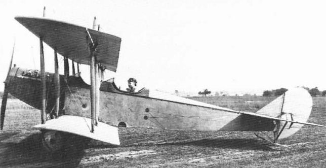
The first Curtiss JN-4 was virtually indistinguishable from the JN-3.
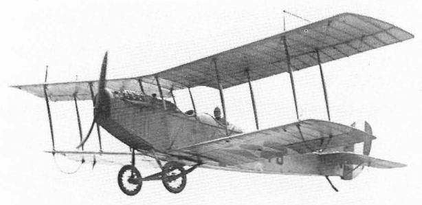
The JN-4A was a later aeroplane than the JN-4B and used B-type tail surfaces. Distinguishing features were the engine down-thrust and Increased wing dihedral.
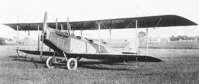
The JN-4B of 1916 was sold to both private owners and the US Army.
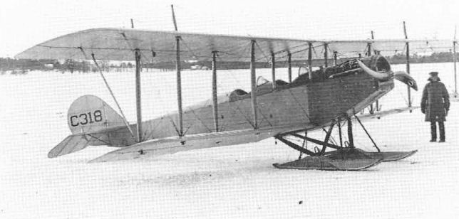
The JN-4Can Canuck follow-on to the JN-3 was developed in Canada. This one was the first aeroplane to fly on skis in Canada. The C-number on the rudder is the Royal Flying Corps Service number and should not be confused with US civil C-registrations issued from 1927.
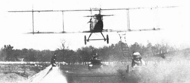
This transfer of a man from a speeding car to a JN-4C Canuck along the straight of a racetrack is representative of some of the Air Circus stunts performed during the Jenny Era of 1920-25.
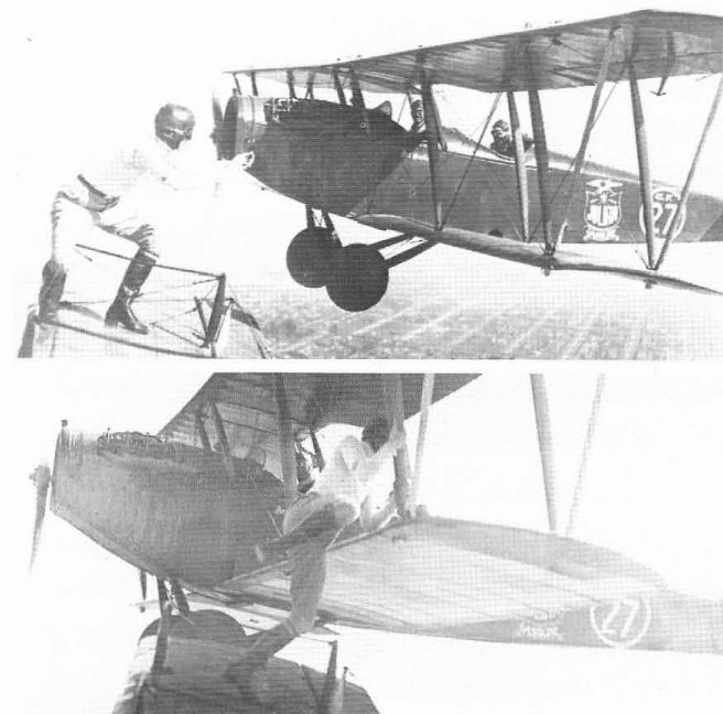
Further antics of the Jenny Era. Gladys Ingle, a lady daredevil, transfers from the upper wing of one JN·4D to the lower wing of another. The kingposts on top of the wing were essential to her stance. The other Jenny has had the kingposts removed and the upper wing overhang braced with struts instead of wires.

The prototype JN-4D of 1917 differed from the production models only in having ailerons fitted to upper and lower wings.
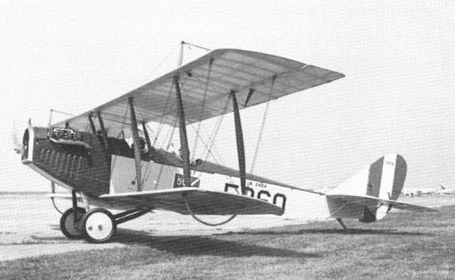
The JN-4D was the principal US Army primary trainer of 1917-18. This is a perfect restoration completed in 1967 by airline pilot Dan Neumann.
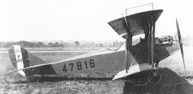
The improved JN-4D-2 was intended to replace the JN-4D, but only this single example was built before the cancellation of war orders. The only outward difference was the level position of the engine relative to the downthrust of the JN-4D.
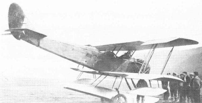
Short-span Hi-lift wings were provided for Jennies by various builders. This JN-4D operated as a seaplane in Alaska into the early 19305.
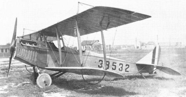
In the JN-4H series the 90 hp Curtiss OX-5 engine was replaced by the 150 hp Wright-Hispano. Note the enlarged radiator. This is the JN-4HB bomber-trainer version.
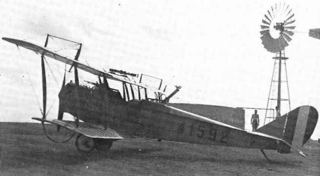
The JN-4HG was used for gunnery training. This example has a synchronized Marlin machine-gun for the pilot, two Lewis machine-guns in the rear cockpit, and a fixed camera gun on top of the upper wing.
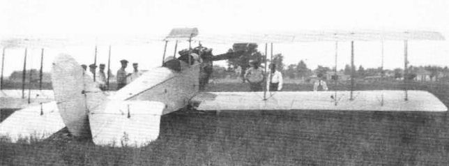
A Long Wing Jenny, a JN-4H with the standard lower wing panels replaced by upper wing panels. Such alterations were made often by ingenious private owners.
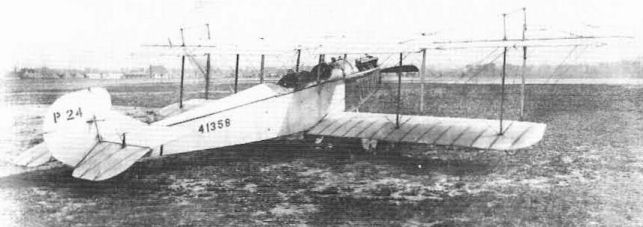
The JN-5 was a JN-4H fitted with short-span wings for improved performance but was not a success. The example illustrated is seen with experimental metalframe JN-4H wings.

The JN-5 was reconverted to a JN-4H and used for test work at McCook Field. Here it is fitted with an early controllable-pitch propeller and an experimental rudder that incorporates a steerable tailskid.
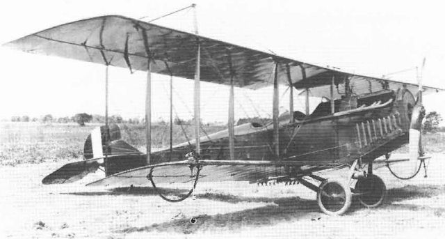
The JN-6H models could be distinguished from the JN-4Hs mainly by the addition of ailerons to the lower wing. This first JN-6HB bomber-trainer is one of a very few to use the JN-5 form of fin and rudder.
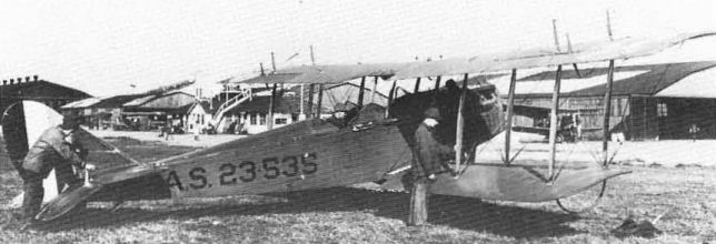
Starting. in 1923, over 200 wartime JN-4s and JN-6s were rebuilt and standardized under the designation of JNS. Absence of lower wing ailerons made them resemble JN-4H models.
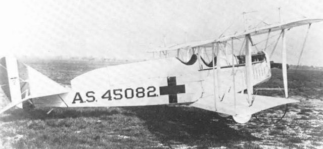
Various Jenny models were converted to ambulances with varying configurations. This one with raised housing for a stretcher case is a former JN-6HG-1 gunnery trainer.
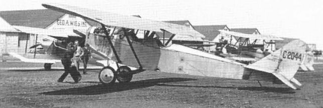
A Sikorsky monoplane wing fitted to a JN-4D. Sperry offered a similar installation. The registration's C prefix meant that the aeroplane was licensed for commercial operation but could not fly outside of the United States.
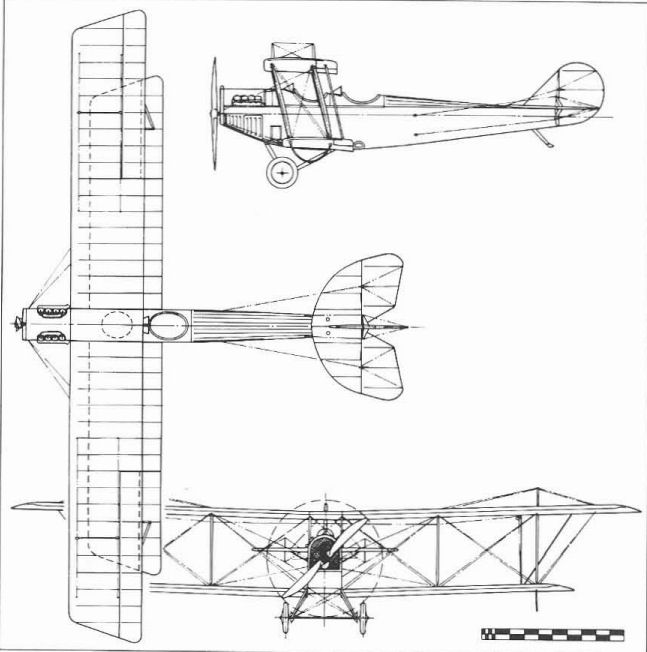
JN-4 Can (Canuck).
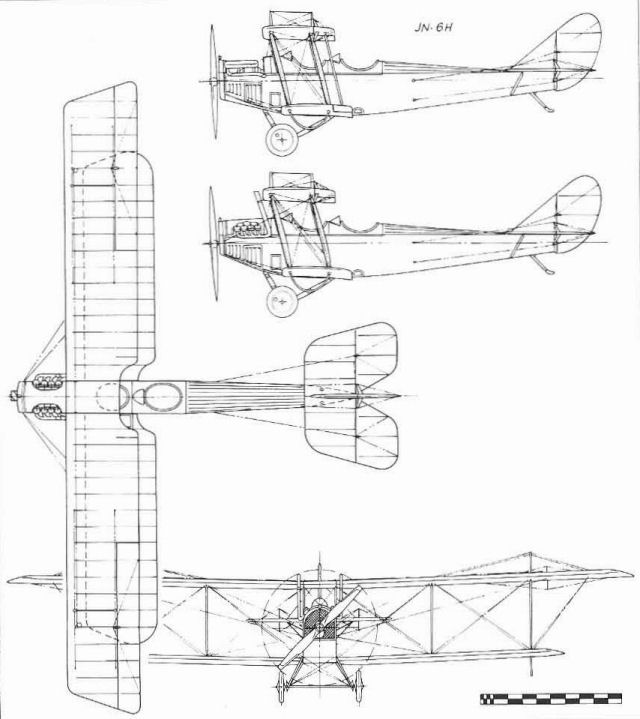
JN-4D and JN-6H.
Twin JN (Model 1B) - The Twin JN of April 1916, tentatively designated JN-5, was an enlargement of the new JN-4 model to a twin-engined type for observation work. Wing span was increased by use of an 11 ft 4 in (3,45 m) centre section for the upper wing and the installation of short panels between each lower wing and the fuselage. The standard JN-4 outer wing panels had one degree of dihedral outboard of the flat centre-sections on the prototype and 3 1/2 degrees on the production versions.
The need for increased tail area was met by installing a Curtiss R-4 rudder and an enlarged fin on the prototype and a modified R-4 fin on the production versions. Directional control was still marginal but was improved somewhat by modifying the starboard Curtiss OXX-2 engine to rotate in the opposite direction to that in the port side unit as was done on earlier Curtiss twin-engined flying-boats.
In spite of the two engines, the Twin JN was still only a two-seat machine and crew efficiency was greatly handicapped by the wide separation between the pilot's cockpit aft of the wing and the observer in the nose.
The US Army acquired eight Twin JNs in 1916 and early 1917, seven by direct purchase and one a donation to the Militia by private citizens. These saw very brief service on the Mexican border in 1916. The US Navy acquired two examples, which were operated as twin-float seaplanes.
One Army model, serial number 428, differed greatly from the other Twin JNs. It was so retrograde in both aerodynamic and structural detail that in the absence of other evidence the author believes it to be an entirely different and somewhat earlier aeroplane, possibly the rumoured 'Twin R'. Since its general configuration was similar to the Twin JN, Curtiss doubtless found it easier to sell this existing aeroplane to the Army as a modified Twin JN than as a new and entirely separate design.
US Army serial numbers: 102/107,428,470 (delivery of 470 doubtful).
US Navy serial numbers: A93, A198
Twin JN
Reconnaissance aircraft. Pilot and observer. Two 90 hp Curtiss OXX-2.
Span 52 ft 9 3/8 in (16,08 m) (upper), 43 ft 1 3/4 in (13,15 m)(lower); length 29 ft (8,83 m); height 10 ft 8 11/32 in (3,26 m): wing area 450,28 sq ft (41,83 sq m).
Empty weight 2,030 lb (921 kg): gross weight 3,110 lb (1,411 kg).
Maximum speed 80 mph (128,74 km/h); climb to 3,500 ft (1,067 m) 10 min: service ceiling 11,000 ft (3,353 m).
One example had a Lewis machine-gun.
Twin R - Early in 1916 Curtiss converted an R-2 airframe to an experimental twin-engined type. No official designation is known beyond the reference to a 'twin-engine R'.
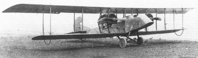
The prototype Curtiss Twin JN was essentially a JN-4 enlarged to a twin-engined type. The propellers rotated in opposite directions.
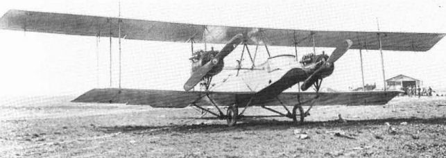
Although delivered to the US Army in 1917 under the designation Twin JN, Serial No.428 appears to be an earlier and less refined design than the other Twin JNs.
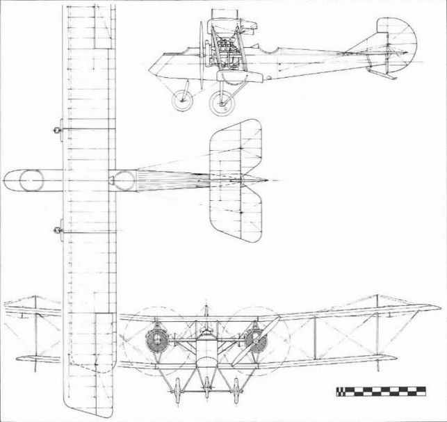
Production twin JN.
Model L (Model 9)
The Model L triplane was a late 1916 development intended as a side-by-side two-seater suitable for training and for operation by private owners. The use of three wings was not unusual for the time. However, the extremely wide gap-chord ratio of the Model L wings compared to contemporary biplanes led Curtiss to develop a different wing strut pattern. Span of the two upper wings was equal while the bottom wing was short. The wider-than-standard fuselage terminated in a horizontal rather than vertical, knife-edge at the tail.
The Model L became a production aeroplane, some being sold to individuals while others were used in the Curtiss flying schools. After the US entered the war, both the US Army and Navy bought limited quantities.
L - The original civil two-seater with 90 hp Curtiss OX engine.
L-1 - An improved L with revised tail and strut details. This was the first time that the first variant of a designated Curtiss model was given a -1 designation instead of being designated -2 for the second configuration. The US Army acquired one when it bought three different triplane models from Curtiss and assigned Army serial number 473 to the L-1.
L-2 - A single-float seaplane version with 100 hp OXX engine used by both the US Army and Navy, The first Navy model was flown with the original short bottom wing of the previous versions but this was soon enlarged to the span of the other wings to add needed lifting area to the heavier seaplane.
US Navy serial numbers: A291/293; US Army serial number: 475.
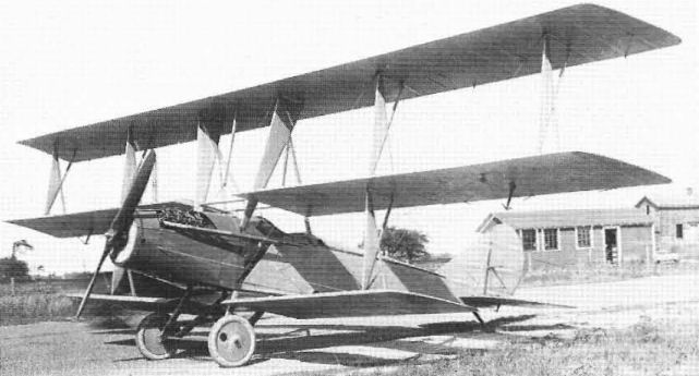
The L-1 was a refinement of the Model L.
R-3 - Two R-3s delivered to the US Navy in 1916 were fitted with twin floats and 160 hp Curtiss V-x engines, Generally similar to the production R-2s, the R-3s had their wing spans increased to 57 ft 1 1/32 in (17,39 m) by the addition of a longer-span centre section for the upper wing and the insertion of extra panels on each side of the fuselage inboard of the standard-length outboard lower wing panels in the manner of the N-9. The wings were rigged without dihedral.
The original Navy identification/serial numbers for its two R-3s were AH-62 and AH-65 in the system adopted in March 1914; after 18 May, 1917, these became A66 and A67 in the new sequential serial number system and operated under their Curtiss model designations.
Eighteen R-3s were ordered by the US Army in 1916 for delivery in 1917, but these appear to have been completed as improved R-6s and R-9s.
R-3
R-3 - Observation seaplane. Pilot and observer. 160 hp Curtiss V-X.
Span 57 ft 1 1/32 in. (17,39m); length 30 ft 11 1/2 in (9,43 m); wing area 609,7 sq ft (56,64 sq m).
Empty weight 3,000 Ib (1,361 kg); gross weight 3,837 lb (1,740 kg).
R-6 (Model 2A) - The R-6 of early 1917 was a long-wing seaplane like the R-3 and differed from it mainly in use of the 200 hp V-2-3 engine and three degrees of dihedral in the outer wing panels. All but one of the seventy-six R-6s delivered to the US Navy had twin floats, serial number A193 being fitted with a single float. Army R-6s were delivered both as landplanes and as twin-float seaplanes. The US Army ordered 18, but most are believed to have been released to the Navy before Army acceptance.
Navy R-6s became the first American-built aeroplanes to serve US forces overseas in World War I when a squadron was assigned to patrol duty in the Azores in January 1918. Average cost of the R-6 and similar R-9 was $15,200 less GFE.
US Navy serial numbers; A162/197 (36), A302/34I (40). US Army serial numbers; 504/521
R-6L - Forty of the Navy's R-6s were converted to R-6L in 1918 by the installation of 360 hp low-compression Liberty engines in the manner of the R-4Ls of the Army. R-6Ls were used for the renewal of Navy torpedo-dropping experiments in 1920 and a number as Service torpedo aircraft until replaced by later equipment. The last R-6Ls were condemned in 1926. An additional fourteen R-6Ls were created by converting the R-9s with serial numbers A919, 920, 925, 943, 956, 958, 963/966, 970, 976, 991, and 994 to R-6 configuration.
R-6L
Observation and torpedo seaplane. Pilot and observer. 360 hp Liberty.
Span 57 ft 1 3/16 in (17,4 m); length 33 ft 5 in (10,18 m); height 14 ft 2 1/32 in (4,31 m); wing area 613 sq ft (56,94 sq m).
Empty weight 3,513 lb (1,593 kg); gross weight 4,634 lb (2,102 kg), or 5,662 lb (2,568 kg) with torpedo.
Maximum speed 100 mph (160,93 km/h); climb in 10 min - 6,000 ft (1,829 m); service ceiling 12,200 ft (3,718 m): range 565 miles (909 km).
Armament - one 1,036 lb (470 kg) torpedo.
R-9 - The R-9 airframes for the Navy were bomber versions of the R-6 with the controls rearranged to place the pilot in the front seat and the observer/bombardier in the rear. Ten (A883/887, A901/905) were transferred to the US Army in February 1918.
US Navy serial numbers: A873/984 (112). US Army serial numbers: 39033/39042 (10)

The R-6 differed mainly from the R-3 in having a more powerful engine and three degrees or dihedral on the outer wing panels.
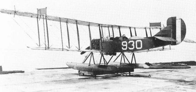
The R-9s were structurally identical to the R-6s but the pilot was in the front seat. The Navy serial number verifies this as an R-9 but the photograph shows wheel control in the rear cockpit.

The Curtiss R-6 of early 1917 was a two seat reconnaissance machines flown by both the US Navy and US Army, who ordered 76 and 18 examples, respectively. It should be noted that eight of the Army machines were transferred to the Navy prior to delivery. Powered by a 200hp Curtiss V-Z-3, the R-6, with its top level speed of 83mph was not a very vivid performer, being best remembered as being the first US aircraft to be operationally deployed overseas. This came about when the US Marines' 1st Aeronautical Company took its R-6s to Ponta Delgada in the Azores, on 21 January 1918. The machine seen here, Bu Aer A 193, is of interest in being the only R-6 to be fitted with a single, central float, plus outriggers, the rest of the R-6s using the conventional twin float arrangement.
Model S (Model 10)
The first Model S of 1916 was a single-seater built to the concepts of what European builders had called a Scout in 1914. This was a single-seat tractor biplane originally used for the work its name implied - the scouting of enemy activity. Early scouts were unarmed but new designs were soon fitted with fixed forward-firing machine-guns; even though they then became fighters or pursuit planes, the term Scout stuck to the single-seaters almost to the end of the war.
Curtiss developed several different Scout models in its S-series of 1916-17, but succeeded in selling only a few to the US Army and Navy. The inadequacy of these aeroplanes cannot be blamed on lack of skill among the Curtiss designers; rather, it showed how far the US aviation industry had fallen behind that of Europe, which was operating under the immediate requirements of the European war. American designers were almost completely cut off from the latest European advances and had to progress from the 1914 designs on their own without the stimulus and large-scale financing of a war economy.
S-1 Speed Scout - Also called Baby Scout, the original Model S-1 was the smallest aeroplane that Curtiss could build around the 90 hp OX engine. Construction was thoroughly conventional for the time, but the 20-ft (6,09 m) span of the single-bay wings was inadequate. The upper wing was lengthened and the strut arrangement was altered to two spanwise Vs. The S-1 did not sell, and Curtiss kept the modified prototype for its own use.
S-2 Wireless - The S-2 was essentially the Model S-1 fitted with new wings and a strut arrangement that eliminated the need for wing bracing wires, hence the name Wireless. The problem of fining shock absorbers in the undercarriage when the wing struts were anchored to the ends of the cross-axle was solved by using the new Ackermann Spring wheels, which featured curved spokes made of flat spring steel that served that purpose; these wheels did not have good resistance to side loads, unfortunately, and were not widely used.
Powerplant: 100 hp Curtiss OXX-2. Span 21 ft 10 in (6,65 m) (upper), 11ft 3 in (3,42 m) (lower). Aerofoil Eiffel 32. Empty Weight 805 lb (365 kg). Maximum speed 119 mph (191,5 km/h).
S-3 (Model 10) - The only 'production' models of the S-series were four S-3 triplanes sold to the US Army early in 1917 (serial numbers 322/325). These used the basic fuselage, engine, and tail of the S and S-2 fitted with single-bay triplane wings using the RAF 6 aerofoil. These were the Army's first single-seat Scouts, but they were still more than two years behind equivalent European types.
S-3
Speed Scout. Single-seat. 100 hp Curtiss OXX·3.
Span 25 ft (7,62 m); length 19 ft 6 in (5,94 m); height 8 ft 7 in (2,61 m); wing area 142,6 sq ft (13,24 sq m).
Empty weight 970 lb (440 kg); gross weight 1,320 lb (599 kg).
Maximum speed 115 mph (185 km/h); climb - 9,000 ft (2,743 m) in 10 min.
S-4 (Model 10A) - This was a triplane similar to the S-3 intended as a seaplane Scout for the US Navy (serial A149). This was Curtiss's first experience with the twin-float configuration. As with other Curtiss seaplanes, it became necessary to increase the span of the S-4 to carry the extra weight. The front float struts collapsed during a heavy alighting in January 1918 and the aircraft was struck off charge.
S-5 (Model 10B) - This was similar to the S-4 except for being fined with a single main float and small wingtip floats. Navy serial number A150, struck off on 6 August, 1919.
S-6 (Model 10C) - The S-6 was an improved version of the S-3 and was the first American Scout fitted with twin forward-firing machine-guns. This may have been only an inoperative test installation intended to check weight, balance, and location, for the guns were gas-operated Lewis models which were not used for synchronized fire through the propeller. The Army ordered twelve early in 1917 but only one, serial number 492, was delivered.
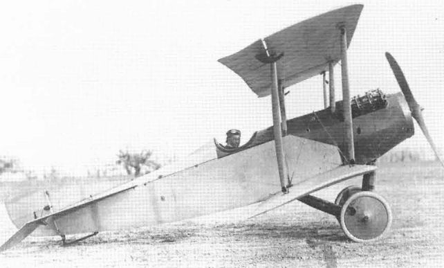
The Curtiss Model S-1 was the smallest aeroplane that could be built to accommodate the 90 hp Curtiss OX engine.

The original 20-ft wing of the Model S-1 was inadequate so the upper span was increased and braced with diagonal struts.

The Curtiss S-2 was named Wireless because the unique strut bracing system eliminated the need for conventional wires.
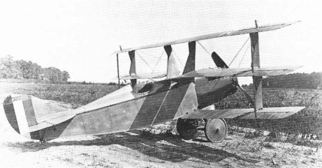
The four US Army Curtiss S-3s of early 1917 carried the new US national aeroplane markings but did not carry guns although they were classified as Scouts, which was synonymous with Pursuit at the time.
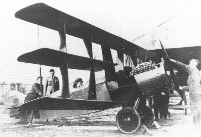
Although tested as a land plane, the S-4 was intended to be a seaplane and had longer wings than the similar S-3 to carry the weight or the floats.
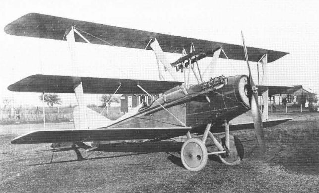
A development of the S-3, the sole Curtiss S-6 was flown in 1917 with an unusual installation of twin Lewis guns above the cockpit.
The S-6 was slightly larger than the S-3 and was the first US Army single-seater to carry machine-guns.
The S-6 was slightly larger than the S-3 and was the first US Army single-seater to carry machine-guns.
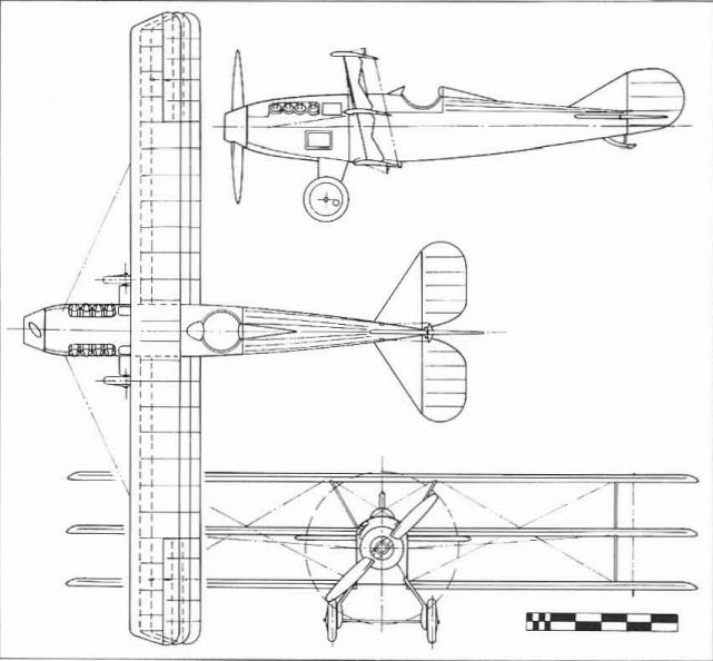
Model S-3 (Model 10).
Model T (Wanamaker Triplane, Model 3)
At the time of its construction in 1915-16, the Curtiss Model T flyingboat, which was instigated by Rodman Wanamaker of America fame, was the largest seaplane in the world. It was also the first four-engined aeroplane built in the United States. An unusual feature was the arrangement of the engines-four 250 hp Curtiss V-4 tractors in a straight line, a feature used successfully up to that time only by the Russian Sikorskys and the single German Siemens-Forsman. Because of marginal directional control under one-engine-out conditions, designers usually grouped engines as close to the aeroplane centreline as possible to minimize the turning couple of an unsymmetrical power condition. A favourite procedure was to pair two side engines in tandem installations in a single nacelle, which Curtiss did on the C-2 in 1919.
The America-type control cabin was equipped for two pilots and an engineer. The control forces were so great that an early form of power boost was provided. Small windmills installed on the wings were connected to the aileron cables by electrically-operated clutches. The power of the windmill was imparted to the cable to aid the pilot. Similar devices were used for the tail controls.
The T was designed to requirements of the British Admiralty, which ordered 20 examples, RNAS serial numbers 3073/3092. While the first T was assembled inside the Buffalo plant, it was not flown in the US because the V-4 engine was not developed in time. The aeroplane was shipped to Britain without engines and 240 hp French Renaults were installed there.
The big triplane was not put into service and the remaining 19 on order were cancelled. The basic design concept was retained, however; the Curtiss Model T was the direct predecessor of the five-engined Felixstowe Fury triplane that Cmdr Porte designed for the Admiralty.
Model T Triplane
Patrol Bomber flying-boat. Crew included two pilots, one engineer, and gunners. Four 240 hp Renault.
Span 134 ft (40,84 m) (top). 100 ft (30,48 m) (centre). 78 ft 3 in (23,85 m)(lower); length 58 ft 10 in (17,93 m); height 31 ft 4 in (9,55 m); wing area 2,812 sq ft (261,23 sq m).
Empty weight 15,645 lb (7,096 kg); gross weight 22,000 lb (9,979 kg).
Maximum speed 100 mph (160,93 km/h); climb to 4,000 ft (1,219 m) 10 min; endurance 7 hr.
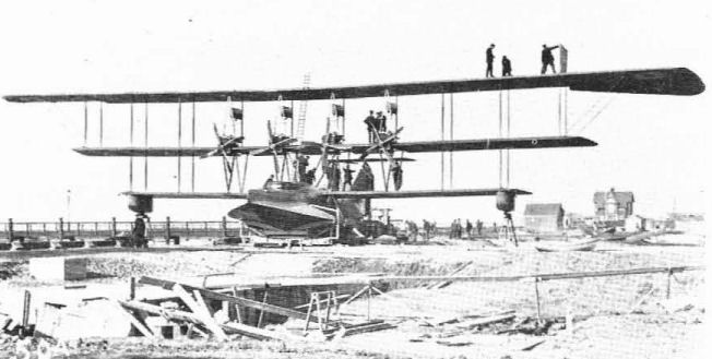
The Model T triplane was too big to be assembled and flown at the Curtiss Buffalo plant so was shipped to Britain, where it was assembled and fitted with French Renault engines.
Autoplane (Model 11)
The Autoplane, known only by that name, was a unique winged car that Curtiss developed quickly for display at the Pan-American Aeronautic Exposition of February 1917. Basically, the design consisted of a set of standard Curtiss Model L triplane wings filled to an aluminium-body three-seater motor car designed and built by Curtiss. A 100 hp Curtiss OXX engine in the standard car position turned a drive shaft to the rear; belts then turned the pusher propeller mounted on a shaft at the top of the car. The tail surfaces were carried on two wire-braced booms spaced 9 ft (2,74 m) apart to clear the propeller and a small auxiliary surface was attached at the extreme nose. The pilot-chauffeur sat in the front seat at conventional Deperdussin controls and two passengers sat side by side in the rear seat.
The unique feature of the Autoplane was that the wings and tail could he removed as a unit to permit the car component to operate as a conventional road vehicle, The Autoplane is reported to have made only a few short straight-ahead hops before development was abandoned upon US entry into the war.
Span 40 ft 6 in (12,34 m); length 27 ft (8,22 m); height 10 ft (3,04 m).
Speed range 45-65 mph (72,4-104,6 km/h).
Useful load 710 lb (322 kg).
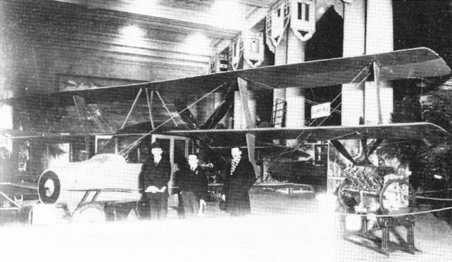
The Curtiss Autoplane of early 1917 had an automobile body with detachable wings from a Model L triplane.
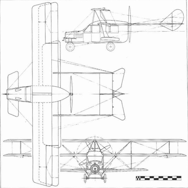
Autoplane (Model 11).
Model BT
The unique BT originated early in 1917 following discussions between Glenn Curtiss and US Coast Guard personnel concerning the possible use of aircraft to deliver lifeboats from shore stations to ships in distress beyond the breakers or at sea. Having a conventional aeroplane carry a boat was ruled impractical. Curtiss then designed what was essentially a winged lifeboat, with a hull more boat-like than on previous flying-boats.
The BT had two unconventional features. The 200 hp Curtiss V-2-3 engine was installed in the hull and drove two tractor propellers through shafts and gears, and the triplane wings and boom-mounted tail surfaces could be jettisoned if necessary to allow the hull to operate as a pure boat driven by a marine propeller and a small auxiliary motor. The pilots sat in a side-by-side cockpit behind the wings.
The power transmission system of the BT proved unworkable from the start. The engine was then installed ahead of the middle wing and turned a single direct-drive tractor propeller. The US Navy bought the modified BT in December 1917 and assigned Navy serial number A2277.
The BT was of no use to the Navy, which encountered problems of hull strength, spray protection for the crew, the proximity of the propeller to the relocated front cockpit, and the danger of hand-starting engines in seaplanes. The BT was surveyed (Surveyed is a US military term meaning written off and ordered to be scrapped) on 9 June, 1919.
Span 57 ft (17,37 m); length 40 ft (12,19 m); height 16 ft (4,87 m).
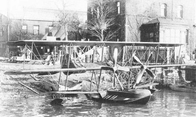
The BT was a flying lifeboat with the engine in the hull. Its wings could be jettisoned after alighting at sea, after which it proceeded as a motorboat
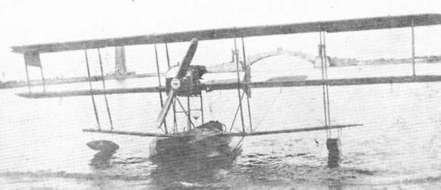
The BT was modified with external powerplant, as shown, and the jettisonable wing feature was discarded.
Model FL (Model 7)
The single FL is a good example of Curtiss innovation - the mixing of major components of two existing models to form a new one. A set of stock Model L wings on the hull and powerplant of' the Model F flying-boat resulted in the entirely logical designation of FL for the single experimental model produced in 1917. It was owned by the American Trans-Oceanic Corp and was advertized for sale in September 1919 at $6,000.
The single FL is a good example of Curtiss innovation - the mixing of major components of two existing models to form a new one. A set of stock Model L wings on the hull and powerplant of' the Model F flying-boat resulted in the entirely logical designation of FL for the single experimental model produced in 1917. It was owned by the American Trans-Oceanic Corp and was advertized for sale in September 1919 at $6,000.
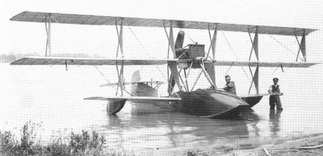
Fitting Model L wings to a Model F hull to produce the Model FL is representative of Curtiss's method or developing new models quickly.
H-12 (Model 6A) - The H-12 of late 1916 was a considerably enlarged version of earlier H-boats and was powered initially with two 160 hp Curtiss V-X-X engines. Eighty-four went to the RNAS, which named them Large Americas. Again, Britain was dissatisfied with the underpowered Curtiss engines and substituted 275 hp Rolls-Royce Eagle I engines in their H-12s, later replaced by 375 hp Eagle VIIIs.
With US participation in the war becoming imminent, funds for the expansion of Naval aviation became available and the Navy was at last able to buy twin-engined flying-boats. The first of twenty H-12s was delivered in March 1917. Engines were the 200 hp Curtiss V-2-3, later replaced with Liberties.
US Navy serial numbers: A152, A765/783
H-12A (Model 6B) - Original H-12s re-engined in Britain with 275 hp Rolls-Royce Eagle I engines and later Curtiss versions altered at the factory for engines to be installed in the United Kingdom. For the H-12A model at least, some hulls were built by the Niagara Motor Boat Company of Tonawanda, NY.
RNAS serial numbers: 8650/8699 (50), N1160/1179 cancelled (20), N1510/1519 (10).
H-12A
Patrol-bomber flying-boat. Four crew.
Two 275 hp Rolls-Royce Eagle I.
Span 92 ft 8 1/2 in (28,25 m); length 46 ft 6 in (14,17 m); height 16 ft 6 in (5,02 m); wing area 1,216 sq ft (112,96 sq m).
Empty weight 7,293 lb (3,308 kg); gross weight 10,650 lb (4.830,75 kg).
Maximum speed 85 mph (136,79 km/h) at 2,000 ft (610 m); climb to 2,000 ft (610 m) 3,3 min, to 10,000 ft (3,048 m) 29,8 min; service ceiling 10,800 ft (3,292 m); endurance 6 hr at cruising speed.
Armament - four flexible .303-in Lewis machine-guns, four 100 lb (45 kg) or two 230 lb (104 kg) bombs.
H-12B (Model 6D) - Believed to be H-12s and H-12As re-engined with 375 hp Rolls-Royce Eagle VIIIs.
RNAS serial numbers: 4330/4353 (24).
H-12L - The US Navy followed the British lead in refilling its H-12s with more powerful engines. When the 360 hp low-compression Liberty became available late in 1917, the H-12s on hand were fitted with these new V-12 engines and were redesignated H-12L. The last H-12Ls were withdrawn from squadron service in July 1920.

H-12As were H-12s with their 200 hp Curtiss engines replaced in Britain by 275 hp Rolls-Royce Eagles.
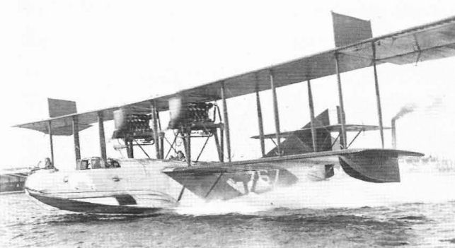
H-12Ls were US Navy production versions of the H-12 fitted with the 360 hp low-compression Liberty engine. Navy wartime colouring was grey overall.
H-16 (Model 6C) - The H-16 was the final model in the Curtiss H-boat line and was built in greater quantities than any or the other twin-engined Curtiss flying-boats.
It was a logical development of the H-12 and was originally intended to use the 200 hp Curtiss V-X-X engine. However, the Liberty became available before the first H-16 was completed so all 124 H-16 deliveries to the US Navy were made with the 360 hp low-compression Liberty. These were replaced by 400 hp Liberty 12As in postwar years. The sixty British versions were shipped without engines and were fitted with 345 hp Rolls-Royce Eagles on arrival in the United Kingdom.
In addition to 184 built by Curtiss, 150 H-16s were built at the Naval Aircraft Factory in Philadelphia. Originally, the Navy-built models were to be identified as Navy Model C, but all were operated as H-16s. The first Curtiss-built H-16 was launched on 22 June, 1918, while the first Navy-built model had come out of the factory on 27 March. H-16s were shipped overseas to US bases in Britain in 1918; H-16s remained in postwar service with the F-5Ls until May 1930. Prices for Navy-built H-16s ranged from $55,547 less engines for the first example down to $21,680 apiece for the last thirty.
Because of their great similarity, identification problems between the H-16 and the F-5L were inevitable. The distinctive features of the H-16 were originally the unbalanced ailerons with significant sweep back toward the tips as on the America and H-12, and the enclosed pilots' cockpit. The rudder was unbalanced, but could not be distinguished from early F-5L outlines because the balance area of the F-5L rudder was below the horizontal tail at that time. In postwar years, some H-16s were fitted with F-5L ailerons, had the pilots' enclosure removed, and were given added balanced area to the top or the rudder, further complicating the identity problem.
US Navy serial numbers: (Curtiss) A784/799 (16), A818/867 (50), A1030/1048 (19), A4039/4078 (40). (NAF) A1049/1098 (50), A3459/3558 (100).
RAF serial numbers: N4890/4949 (60) (4950/4999 cancelled).
H-16-1 - One H-16 had its engines turned around and was completed as a pusher. No advantage accrued; the adaptation proved to be excessively tail-heavy.
H-16-2 - A second pusher H-16 (A839) was produced by Curtiss with more consideration for the change of balance. Wings of slightly increased span were swept back 5 1/2 degrees. Straight-chord ailerons used with F-5L-type horn balance brought the revised span to 109 ft 7 in (33,27 m). The increased wing area required additional rudder area in the form of two auxiliary rudders mounted on the tailplane.
H-16
Patrol-bomber flying-boat. Four crew.
Two 400 hp Liberty 12A.
Span 95 ft 0 3/4 in (28,97 m); length 46 ft 1 1/2 in (14,05 m); height 17 ft 8t in (5,4 m); wing area 1.164 sq ft (108,13 sq m).
Empty weight 7,400 lb (3.356,58 kg); gross weight 10,900 lb (4.944,15 kg).
Maximum speed 95 mph (152,88 km/h); climb 4,700 ft (1,432 m) in 10 min; service ceiling 9,950 ft (3.03) m): range 378 miles (608 km).
Armament 5-6 flexible 0.30-in Lewis machine-guns, four 230 lb (104 kg) bombs.
Model F-5L
Although it clearly showed its ancestry in earlier Curtiss twin-engined flying-boats, the F-5L did not carry a Curtiss designation. Actually, it was not even a Curtiss design; it was one of several established European models chosen for production in the United States in 1917.
The F-5L evolved from the original America of 1914 after Lt Porte, one of its designers, returned to England after the war began. For the Royal Naval Air Service he developed improved versions of the America, the several H-boats called Small Americas, and the H-12 Large America that Curtiss supplied to the RNAS. The first of the production British-built developments was the F.2, the F standing for the government aircraft plant at Felixstowe.
The wings, empennage, and powerplant arrangement of the British F-boats were essentially Curtiss; Porte's principal contribution to the design was an improved hull. Porte's F.5 model was a parallel design to Curtiss's H-16. While the British F.5s used 345 hp Rolls-Royce Eagle engines, the American versions, redesigned to American standards by the US Navy, were built with Liberties, hence the letter L in the designation. The principal recognition points between the F-5L and the improved Liberty-engined H-16 was the horn-balanced parallel-chord aileron and balanced rudder of the former, and its noticeably different hull lines and open cockpits instead of the enclosed cabin of the H-16. Although the F-5L design belonged to the US Government, its well-known Curtiss ancestry, plus the fact that some were built by Curtiss, has caused it to be widely regarded as a Curtiss. Curtiss built sixty F-5Ls, Canadian Aeroplanes Ltd built thirty, and the US Naval Aircraft Factory built 138. After the war, redesigned vertical tail surfaces were introduced by the Navy on the two of the last three Navy-built F-5Ls which were redesignated F-6. These new tails were then retrofitted to all F-5Ls in service.
When the Navy adopted an aircraft designation system in 1922, aircraft already in service retained their original designations but the F-5Ls unofficially became PN-5 (P for Patrol, N for Navy, regardless of actual manufacturer). Two F-5L hulls were fitted with entirely new wings and 525 hp geared Wright T-2 engines in 1923 and became PN-7s. Duplicate models with the hull built of metal instead of wood were PN-8s. Further Navy-designed variants continued up to PN-12, with production versions of the PN-12 being built by Martin as PM-1 and -2, Douglas as PO-1, Keystone as PK-1, and Hall as PH-1, -2, and -3 in the late 1920s and early 1930s. The Halls served into 1943 to carry the direct descendants of the America through two World Wars.
Early in 1919 F-5L A3864 was modified by the Navy to a tandem-engine design to test the concept of one tractor and one pusher engine in a single nacelle for possible modification of the existing NC-1 and NC-2 three-engined flying-boats. This variant survived to March 1925.
A number of surplus F-5Ls were converted to 16/20-passenger transports by several overwater airlines in the 1920-24 era. Postwar price direct from the Navy was $12,400 while new prices for Navy-built F-5Ls ranged from $56,099 less engines for the first to $20,495 for the last.
F-5L
Patrol flying-boat. Four crew.
Two 400 hp Liberty 12A.
Span 103 ft 9 1/3 in (31,62 m); length 49 ft 3 3/4 in (15,03 m); height 18 ft 9 1/4 in (5,72 m); wing area 1,397 sq ft (129,78 sq m).
Empty weight 8,720 lb (3.955,3 kg); gross weight 13,600 lb (6.168,85 kg).
Maximum speed 90 mph (144,83 km/h); climb to 2,200 ft (670 m) 10 min; service ceiling 5,500 ft (1,676 m); range 830 miles (1,335 km).
Armament - 6-8 flexible 30-in machine-guns, four 230 Ib (104 kg) bombs.
Serial numbers: Canadian Aeroplanes - A3333/3362 (30); Naval Aircraft Factory A3559/4035, 4038 (343 of 480 cancelled); Curtiss - A4281/4340 (60); Naval Aircraft Factory F-6L - A4036,4037.

The single H-16-1 was a standard H-16 with the engines installed as pushers.
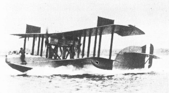
Curtiss installed tandem engines in one F-5L to test the concept before making modifications to the first two NC boats.

Model F-5L.
Model HS Series (Model 8)
In mid-1917, Curtiss converted the three-seat H-14 twin pusher flying-boat into a single-engined model and assigned the new designation of HS for Model H, Single-Engine.
With the US now involved in the war, the Navy ordered a modified version of the HS into large-scale production. Existing Curtiss plants were overloaded and Curtiss couldn't meet the Navy's requirements for the HS. Consequently, five other manufacturers were given Navy contracts to build HS-boats under licence from Curtiss. Of the 1,092-aeroplane total, Curtiss built 675. Production ended when contracts were cancelled after the Armistice; only aeroplanes in an advanced stage of construction were completed in 1919. The type remained in Navy service into 1928 and in civil use in the US and Canada for a few years longer.
HS-1 - A traditional pusher flying-boat with 200 hp Curtiss V-X-3 engine driving a three-blade propeller, converted from the unsuccessful H-14 airframe.
On 21 October, 1917, the HS-1 prototype was the test bed for the first flight of the US Government's new 360 hp twelve-cylinder Liberty engine and was later converted to HS-1L standard.
HS-1L - Significant changes were made in the production version of the HS-1, which was designated HS-1L because of the Liberty engine installation. The most noticeable difference from the prototype was the use of horn-balanced ailerons on both wings - these were the first used by Curtiss on a production aeroplane - and two degrees of dihedral in the outer wing panels. Up to 360 lb (163 kg) of bombs or depth charges could be carried on underwing racks and the defensive armament was a pair of .303-calibre Lewis machine-guns on a Scarff-ring around the front cockpit. Colouring was the new overall light grey adopted as standard Navy camouflage into 1920.
The exact number of HS-1Ls flown is not known because some ordered as HS-1L were completed as HS-2L and others were converted later. Of the six builders of HS boats, only Curtiss and L.W.F. delivered HS-1Ls. Approximately 163 HS-1Ls were delivered to France in 1918, where they operated from ten US Naval Air Stations. The first ones arrived on 24 May and the first patrol was flown on 13 June.
In 1920, the Naval Aircraft Factory fitted stock HS-1L wings to fifteen new tractor-type aeroplane fuselages to create the PT-1 torpedo seaplane (serials A6034/6048).
HS-2L - The 180-lb (82 kg) depth charges carried by the HS-1Ls proved to be ineffective against submarines; heavier charges (230 lb/l04 kg) were needed but the HS-1L could not carry them. This deficiency was overcome by the old Curtiss trick of increasing the wing span; a new centre-section 12 ft (3,65 m) wider was fitted and one 6 ft (1,82 m) panel was installed between each lower wing panel and the hull to create the longer-span HS-2L. The vertical tail was also enlarged and balance area was added to the rudder.
The contract quantities and actual deliveries of HS-boats from the six manufacturers are listed here. Average unit cost was $30,000.
Model Manufacturer Ordered Delivered US Navy serial numbers
HS-1L/HS-2L Curtiss 675 675 A800/815, A1549/2207*
HS-1L/HS-2L L.W.F. 300 250 A1099/1398**
HS-2L Standard 150 80 A1399/l548
HS-2L Gallaudet 60 60 A2211/2276
HS-2L Boeing*** 75 25 A4231/4255
HS-2L Lougheed 2 2 A4228/4229
HS-2L Assembled by 25 A5564/5569, A5615/5619,
Navy from A5787, A5808, A6506,
spare parts in A6507/6513, A6553/6556
postwar years
* HS-2Ls start at A1820.
** HS-2Ls start at A1223.
*** The Boeing-built HS-2Ls could be identified by the absence of lower wing ailerons.
At least nineteen of the 182 HS-boats delivered to France were the HS-2L model. Some HS-2Ls fitted with improved 400 hp Liberty engines remained in Navy service until September 1928. After 1920, standard colouring was grey hull with silver wings and tail and chrome yellow on top surface of upper wing and horizontal tail. Thirty surplus HS-2Ls were sold to the Canadian Air Force and eventually came into civil use into the 1930s. Others were used for short-haul airline work in the US in the late I 920s. The US Navy fitted HS-2L wings to more tractor-type fuselages to create eighteen PT-2 torpedo aircraft (A6326/6343).
HS-3 - The HS-3 was a major redesign of the HS-1L/HS-2L that fitted HS-2L wings to a completely new hull and vertical tail design developed jointly by Curtiss and the Navy. The major change was widening the hull to eliminate the sponsons. The Armistice ended official interest in the HS-3 as a Service type and only four were completed by Curtiss (A5459/5462) and two by the Naval Aircraft Factory (A5590, 5591) at $23,570 each less engines.
HS Series
Patrol f1ying-boal. Two or three seats in two cockpits. 360 hp low-compression Liberty 12.
HS-1L HS-2L HS-3
Span. 62 ft 1 in 74 ft 1 in 75 ft 6 in
(18,92 m) (22,58 m) (23,01 m)
Length 38 ft 6 in 39 ft 38 ft 7 in
(11,73m) (11,88m) (11,76 m)
Height 14 ft 7 in 14 ft 7 in 14 ft 7 in
(4,44 m) (4,44 m) (4,44 m)
Wing area 653 sq ft 803 sq ft 824 sq ft
(60,66 sq m) (74,59 sq m) (76,54 sq m)
Empty weight 4,070 lb 4,300 lb 4,550 lb
(1,846 kg) (1,950 kg) (2,064 kg)
Gross weight 5,910 lb 6,432 lb 6,432 lb
(2,680 kg) (2,917 kg) (2,917 kg)
Maximum speed 87 mph 82,5 mph 89 mph
(140 km/h) (132,76 km/h) (143,22 km/h)
Climb in 10 min 1,725 ft 2,300 ft 3,120 ft
(526 m) (701 m) (951 m)
Service ceiling 2,500 ft 5,200 ft 6,500 ft
(762 m) (1,585m) (1,981 m)
Endurance 4,2 hr 4,5 hr 5,3 hr
(full throttle)
Armament. One flexible 0.30-in Lewis machine-gun (all models), two 230 lb (104 kg) bombs (HS-2L and HS-3)
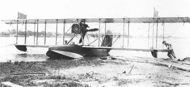
The first HS-1 was converted from twin-engined H-14; the letters HS stood foк a Model H with a single engine
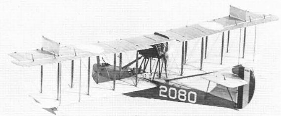
The HS-2L had 12 ft greater wingspan than the HS-1L and four bays of outer wing struts instead of three. This one is in the postwar colours of grey hull, silver wings and tail, and yellow on the top surface of the upper wing.

The HS-3 was essentially the HS-2L with redesigned hull and vertical tail surfaces.
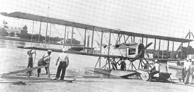
The PT-2 resulted from the US Naval Aircraft Factory fitting standard HS-2L wings to a conventional two-seat fuselage to create a twin-float torpedo plane.
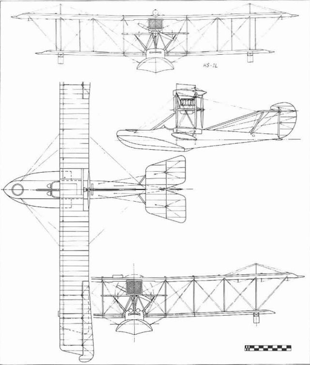
Model HS-2L.
Judson Triplane (Model 7)
This undesignated triplane is an example of several one-only aeroplanes developed by Curtiss to the specific requirements of the customer. It was built late in 1916 or early in 1917 for a Mr Judson as a slightly enlarged triplane version of the standard Curtiss F-boat using the 150 hp Curtiss V-X engine.
Refurbished after the war and fitted with a 400 hp Curtiss K-12 engine, the Judson Triplane was used for exploration in South America.
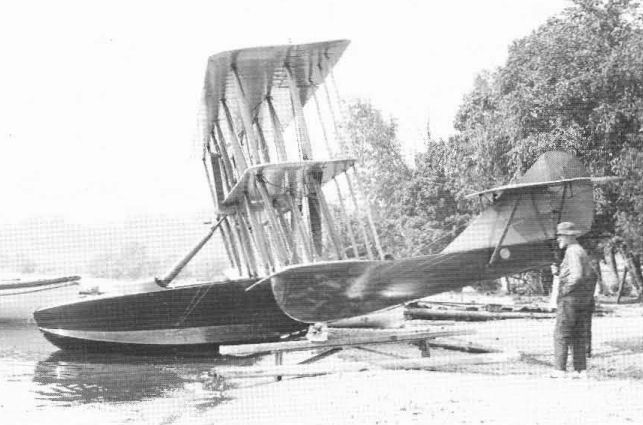
The Judson Triplane of late 1916 was a development of the Model F into a larger and more powerful flying·boat
N-9 (Model 5) - The N-9 of late 1916 was essentially a JN-4B fitted with the 100 hp Curtiss OXX engine, a single float, a lengthened centre section, and 5 ft (1,52 m) lower wing extensions on each side of the fuselage in the manner of the prototype N-8 in order to carry the additional weight of the floats. The control system was the Deperdussin type with the control wheel operating the ailerons and a foot-bar controlling the rudder. The prototype used JN-4B vertical tail surfaces and oversized ailerons; the vertical fin was enlarged on production models.
The US Army made limited use of the N-9, ordering fourteen early in 1917; the Navy was the principal user, ordering a total of 560 as primary trainers. Of these, only 100 were built by Curtiss; the rest were from Curtiss's wholly-owned subsidiary, the Burgess Co of Marblehead, Mass. Fifty additional airframes were built up at Navy bases from spare parts in the early 1920s; N-9s remained in US Navy service into 1927.
N-9C - Two designations were applied to the Navy N-9s. N-9C was not official but came into use after the later N-9H appeared in order to distinguish the original Curtiss-powered N-9s from the later versions. The principal identification point of the -9C was the exposed cylinder banks of the distinctive Curtiss OXX engine and the use of a nose radiator enlarged slightly over that of the JNs and the N-8 by having a curved area added at the bottom.
US Navy serial numbers: (Curtiss) A60/65 (6), A85/90 (6), A201 /234 (34), A294/301 (8), A342/373 (32), A2285. (Burgess) A409/438 (30), A999/1028 (30), A2351/2409 (59).
US Army serial numbers: 433/446 (14).
N-9C
Trainer seaplane. Two pilots. 100 hp Curtiss OXX.
Span 53 ft 4 in (16,25 m); length 29 ft 10 in (9,09 m); height 10 ft 10 1/2 in (3,31 m); wing area 496 sq ft (46,07 sq m).
Empty weight 1,860 lb (844 kg); gross weight 2,410 lb (1,093 kg).
Maximum speed 70 mph (112,65 km/h); climb in 10 min - 2,000 ft (610 m); range 200 miles (322 km).
N-9H - The N-9H designation was official, the letter identifying the 150 hp Wright-Hispano engine (Also known as the Wright A and the 'Hisso'). This installation differed considerably from the N-9C. The cylinder banks were exposed as on the N-9C but were different in appearance. The use of a large spinner over the propeller hub precluded the use of a nose radiator, so the cooling was done by a large column-like radiator that projected well above the wing. The Navy tested some N-9Hs with the 150 hp Curtiss K-6 engine but did not adopt the new powerplant. Cost was $10,050 less GFE.
US Navy serial numbers: (Curtiss) A2286/2290 (5). (Burgess) A2410/2572 (163), A2574/2650 (77). (NAS Pensacola postwar assembly) A6528/6542 (15), A6618/6633 (16), A6733/6742 (10), A7091/7100 (10).
N-9H
Trainer seaplane. Two pilots. 150 hp Wright A.
Span 53 ft 4 in (16,25 m); length 30 ft 10 in (9,39 m); height 10 ft 11 in (3,32 m); wing area 496 sq ft (46,07 sq m).
Empty weight 2,140 lb (971 kg); gross weight 2,750 lb (1,247 kg).
Maximum speed 78 mph (125,52 km/h); climb in 10 min - 3,240 ft (987 m); service ceiling 6,600 ft (2,012 m).
N-10 - The N-10 was not a new design in the Curtiss N-series. The two known examples were one Curtiss N-9C (A365) and one Burgess N-9H (A2473) fitted with shortened equal-span two-bay wings to produce a faster aeroplane for other than primary training duty. The Curtiss model was later refitted with the Wright-Hispano engine.
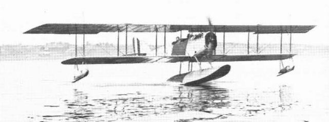
The Curtiss N-9 was the standard US Navy primary trainer of World War I and early 1920s. Early models with Curtiss engines were retroactively identified as N-9C to distinguish them from later N-9H models with Hispano-Suiza engines.
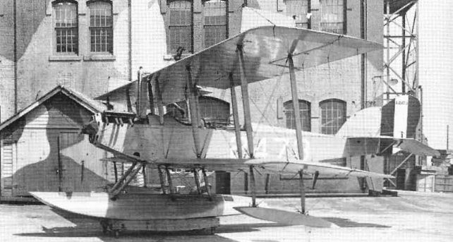
Two N-10s were standard N-9 airframes fined with shorter-span wings for livelier performance as gunnery trainers.
Stinson Special
In early 1917, before the wartime ban on private flying in the US, the famous aviatrix Katherine Stinson commissioned Curtiss to build her a single-seat exhibition aeroplane. The result was a quick adaptation of an S-model triplane fuselage to new two-bay biplane wings, a 100 hp OXX engine, and modified JN-4 tail surfaces.
Miss Stinson, exempted from the ban on civil flying because of her use of the aeroplane in fund-raising activities, gave many exhibitions in the US and Canada in 1917 and 1918. The aeroplane underwent several minor modifications at the hands of its owner as the result of repairs or desired improvements.
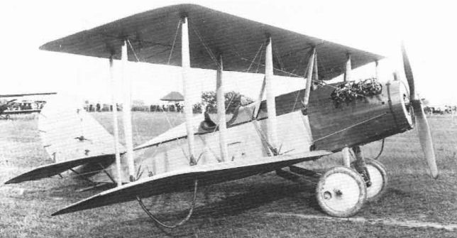
This special single·seat aerobatic aircraft was built for Katherine Stinson by fitting a Model S triplane fuselage with new biplane wings.
Model X-1
The single X-1 of early 1917 was a contemporary of the L-1 triplane, using the same wings and engine installation but a different fuselage, undercarriage, and tail. The most noticeable differences were the use of a two-cockpit tandem-seating fuselage much like that of the JN-4, with vertical tail post, and a JN-4 type vertical tail. The US Army bought one, serial number 474.
The single X-1 of early 1917 was a contemporary of the L-1 triplane, using the same wings and engine installation but a different fuselage, undercarriage, and tail. The most noticeable differences were the use of a two-cockpit tandem-seating fuselage much like that of the JN-4, with vertical tail post, and a JN-4 type vertical tail. The US Army bought one, serial number 474.

The Model X-1 was similar to the JN-4B except for nose details and the use of triplane wings.
Model 18 Series (Model 15)
In March 1918, the Navy authorized Curtiss to build two two-seat fighter triplanes designed at Garden City by Curtiss engineer Charles Kirkham, Navy serial numbers A3325 and A3326. Unit prices were $55,400 less GFE. Although these were identified in service as Model 18T (for triplane) and were also known as Curtiss-Kirkhams, they carried the Curtiss engineering designation of Experimental 502.
The 18 was designed specifically for the 400 hp Curtiss-Kirkham K-12 engine, a water-cooled geared V-12 type of somewhat unorthodox construction developed late in 1917. The K-12 gave the Model 18 world-record performance in 1918 and evolved into the C-12 and eventually into the D-12 and the Conqueror.
The fuselage was a well-streamlined structure featuring a combination of previous Curtiss flying-boat practice and German laminated wood veneer construction in a new process called Curtiss ply. The nose was kept as streamlined as possible by mounting the radiators on the sides of the fuselage. Armament was a pair of .30-calibre Marlin machine-guns on the nose, a pair of .30-calibre Lewis guns on the rear cockpit Scarff ring, and a single Lewis firing out of the belly.
18T-1 Wasp - Kirkham chose the triplane configuration for his new fighter because the shorter span would enhance the manoeuvrability. The -1 was added to the designation after alternate wings of longer span became available on a -2 version. In all configurations, the 18T was known as the Wasp but, because of the sound of its wires during landing approaches, it was known around Garden City as Whistling Benny.
For its first flight, on 5 July, 1918, the 18T had straight wings; tail heaviness was soon corrected by sweeping the wings back five degrees. The Army became interested in the design and arranged to borrow the first one from the Navy. Tests with full military load in August 1915 produced a top speed of 163 mph (262,3 km/h), making the 18T the world's fastest aeroplane at the time even though the record was not recognized. The Army then ordered two 18Ts of its own with Army serial numbers 40054 and 40059.
No Navy production orders were received for the 18T; its hand-built engine was more experimental than the aeroplane itself and the end of the war killed any requirement for it as a Service type.
The speed of the 18T-1 was put to good use, however, since the Navy entered both examples in postwar air races. Both were flown in the 1920 Pulitzer Trophy Race but dropped out because of engine trouble. As single-float seaplanes, both were entered in the 1922 Curtiss Marine Trophy Race. A3325 (painted green, Race No.5) dropped out with engine trouble and A3326 (painted yellow, Race No.4) was in the lead when it ran out of fuel just short of the finishing line. As landplanes again, both were entered in the 1923 Liberty Engine Builder's Trophy Race for Service two-seaters. A3325 crashed during a trial flight and A3326 (Race No.3) broke its crankshaft during the race and was destroyed.
The first of the two Army 18T-1s was delivered to McCook Field for static test in February 1919.
18T-2 - Since the Navy had no urgent need for both 18s after the Armistice, A3325 was left at Garden City for further testing. A longer set of wings, with two bays of struts and a span of 40 ft 7 1/2 in (12,25 m), was fitted, creating the 18T-2 designation. On 18 September, 1919, Curtiss test pilot Roland Rholfs set a new world's altitude record of 34,910 ft (10,640 m) with this aircraft. Fitted with floats, A3325 also set a world's seaplane altitude record.
In 1919, Curtiss built a fifth 18T as a civil aeroplane. Fitted with long wings, it was sold to Bolivia, where it became the first aeroplane to fly from the capital city of La Paz at an elevation of 13,500 ft (4,115 m). After consistent performance there it crashed on 19 May, 1921.
18B Hornet (Model 15A) - After introducing the 18T, Curtiss offered the same design with more conventional two-bay biplane wings and designated it 19B. This was known as Experimental 510 but was publicized as the Hornet. The Army ordered two in August 1915, with Army serial numbers 40058 and 40064. The first was delivered for static test in June 1919; the flight test aircraft crashed soon after delivery.
Model 18
Model 18T-1 - Fighter/Observation landplane. Pilot and gunner/observer. 400 hp Curtiss K-12.
Span 32 ft (9,75 m); length 23 ft 4 in (7,11 m); height 10 ft 2 in (3,09 m); wing area 288 sq ft (26,75 sq m).
Empty weight 1,980 lb (898 kg); gross weight 3,050 lb (1,383 kg).
Maximum speed 163 mph (262,31 km/h); climb in 10 min - 12,500 ft (3,810 m): service ceiling 23,000 ft (7,010 m); endurance 5,9 hr.
Armament - two fixed Marlin and three flexible Lewis machine-guns.
Model 18T-2 - Fighter/Observation seaplane. Pilot and gunner/observer. 400 hp Curtiss K-12.
Span 40 ft 7 1/2 in (12,25 m); length 28 ft 3 7/8 in (8,63 m); height 12 ft (3,65 m); wing area 400 sq ft (37,16 sq m).
Empty weight 2,417 lb (1,096 kg); gross weight 3,572 lb (1,620 kg).
Maximum speed 139 mph (223,69 km/h); climb in 10 min - 10,400 ft (3,170 m); service ceiling 21,000 ft (6,400 m).
Armament - one fixed Marlin and one flexible Lewis machine-gun.
Model 18B - Fighter/Observation landplane. Pilot and observer/gunner. 400 hp Curtiss K-12.
Span 37 ft 6 in (11,43 m); length 23 ft 4 in (7,11 m); wing area 306 sq ft (28,42 sq m).
Empty weight 1,690 lb (766 kg); gross weight 2,867 lb (1,300 kg).
Armament - two fixed Marlin and two flexible Lewis machine-guns.
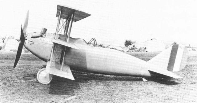
The original version of the Model 18T (for triplane) Wasp was tail heavy with the unswept wings shown.
A PROMISING AMERICAN MACHINE. - The Curtiss-Kirkham triplane, which has, we are informed, put up some very excellent performances during her preliminary trials. Over a measured course an average speed of 160 m.p.h. was attained, while in another test an altitude of 26,300 ft. was reached.
A PROMISING AMERICAN MACHINE. - The Curtiss-Kirkham triplane, which has, we are informed, put up some very excellent performances during her preliminary trials. Over a measured course an average speed of 160 m.p.h. was attained, while in another test an altitude of 26,300 ft. was reached.
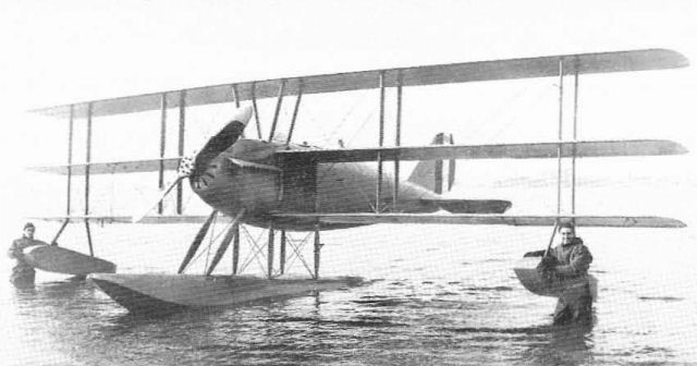
When fitted with longer wings as either a landplane or seaplane, the Curtiss Wasp was designated 18T-2. The short-wing version became 18T-1 retroactively.
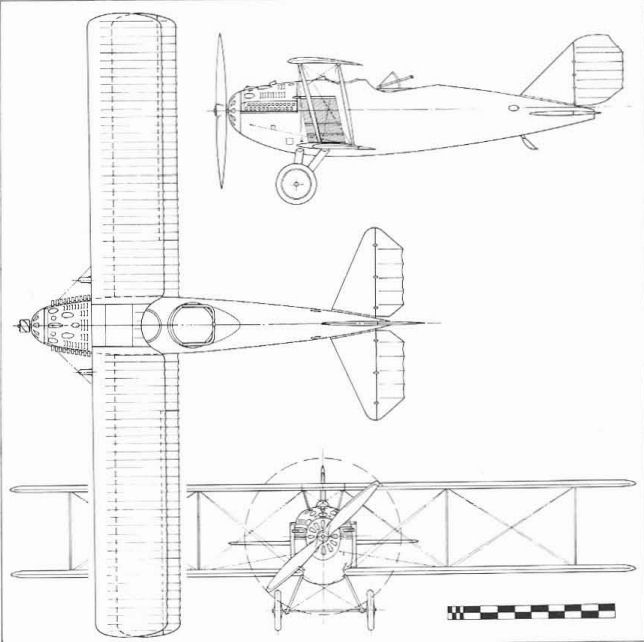
Model 18B Hornet.
Model CB
One example or the CB, the letters believed to mean Curtiss Battleplane, was built at Buffalo early in 1918. This was a two-seat fighter type intended to be Curtiss's successor to the troublesome Liberty-engined Bristol Fighter. The fuselage was an early example of Curtiss ply construction, where two layers of two-inch wide wood veneer strips were cross-laminated over a form to build up a monocoque fuselage shell.
Unusual features of the CB by contemporary practice were the installation of the radiators under the leading edges of the upper wing near the fuselage, where they had a very detrimental effect on airflow over the wing and into the tail, and the lowering of the upper wing to the top of the fuselage. While this provided the rear gunner with a fine field of fire and the pilot with good upward visibility, the pilot's view forward and down was impaired, although small windows in the side of the fuselage gave some help. The main disadvantage of the lowered wing was the aerodynamic penalty of the very narrow wing gap that resulted.
The CB crashed early in the test programme and no further development was undertaken.
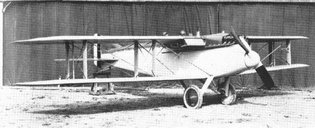
The CB Battleplane was Curtiss's attempt to replace the unsatisfactory Bristol with another Liberty-engined two-seat fighter.
Model GS
In 1917 the Navy gave Curtiss a contract for five single-seat seaplane scouts to be powered with the American-built version of the 100 hp French Gnome rotary engine. This was the first Curtiss design laid down from the start with a rotary engine and was given the designation of GS for Gnome Scout. The designation was altered to GS-1 and GS-2 when a contract for one additional GS was received,
The aeroplane designated GS-1, Navy serial number A868, was the sixth GS. It was a triplane that drew heavily on Curtiss experience with the S-3 to S-6 and other triplanes. Other than the three wings, the unusual feature of the GS-1 was the incorporation of shock absorbers in the struts between the fuselage and the main float. Seaplanes with their rigid truss between float and fuselage had always taken a beating during rough-water take-offs and alightings, but the GS-1 seems to have been the first aeroplane on record in which something has been done about it. Unfortunately, the scheme didn't work well. The flexibility m the rigging allowed the trim angle of the float to change at high speed on the water and induce undesirable porpoising of the entire aeroplane. The GS-1 was nicknamed 'Flying Door Knob Control' by Curtiss pilots because of the detail of one of the controls on the tricky carburation system of the rotary engine.
The GS-1 was delivered to the Navy in Florida on 1 January, 1918. After demonstration by a Curtiss test pilot, the Navy acceptance pilot made several flights but damaged the machine beyond repair on a landing on 1 April.
The first five Gnome Scouts, Navy serial numbers A445/449, were biplanes. These were not merely two-winged versions of the GS-1 but were entirely different designs. Little is known of these beyond photographs and Curtiss test pilots' comments on their tail heaviness. First acceptance was on 14 February, 1918, and the last was on 9 August. A447 was sold as surplus in August 1920 and A449 was struck off charge in November 1923.
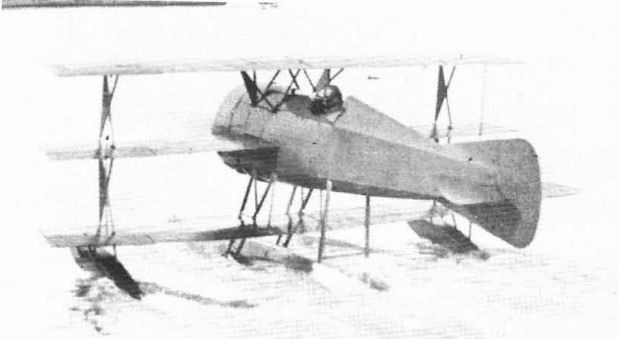
The GS-1 of late 1917 was the last of a Navy scout order and was completed as a triplane.
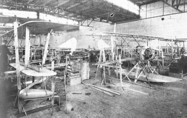
The first five Navy Gnome Scouts were completed as GS-2 biplanes; these were the only Curtiss aeroplanes designed from the start for rotary engines.
Model HA (Model 16)
The HA series of 1918 had no connection with the H-series flying-boats that originated in 1914. The HA was not even a Curtiss design; it was designed by Captain B. L. Smith of the US Marine Corps, and the Curtiss Engineering Corporation at Garden City was given a contract to build a prototype in December 1917. Two others were ordered later. Powered with the new Liberty engine, the two-seat seaplane was named Dunkirk Fighter because it was intended to establish Allied air superiority over the Belgian coastal area around Dunkirk, then held by the Germans.
Construction of the first HA, Navy serial A2278, was conventional wood and fabric, but there were several notable departures from standard configuration. The Liberty engine was entirely buried in the nose of a fat fuselage that was rounded out by formers and stringers outside of the basic rectangular structure. The nose was tipped with a large-diameter spinner. The single main float was mounted on two centreline struts and was stabilized by bracing wires running out to the inner bay of wing struts. The wing arrangement was unusual in that the upper wing, which had its roots resting on the top of the fuselage, was rigged with dihedral while the lower wing was rigged with anhedral. The pilot in the forward cockpit sat in a large cutout behind the rear spar of the upper wing while the gunner had a conventional cockpit and two-gun Scarff ring.
The first HA was ready for flight on 21 March, 1918. It was so tail heavy as to be almost unmanageable in the air and Curtiss's best pilot Roland Rohlfs managed to bring it down in a series of swoops to a crash landing that destroyed the aeroplane.
HA-1 - Curtiss was then given a contract for two additional HAs, Navy serials A4110 and 4111, and some parts of the first one were incorporated into a considerably revised second prototype designated HA-1. Main changes were redesigned vertical tail surfaces with fixed vertical fin area above and below the fuselage, a more rearward location for the wings, and deletion of the spinner in favour of a nose radiator installation. Price less GFE was $42,900.
The performance of the A4110 was greatly improved, but it caught fire in the air. Pilot Rohlfs got it down safely but A4110 was a total loss.
HA-2 - The third HA was fitted with entirely new wings and became the HA-2. The new wings were of two-bay type with no dihedral on either panel. A centre section for the upper wing was held above the fuselage on conventional struts. The Armistice ended further military development of the HA design but the speed of the surviving example encouraged the Navy to enter it in the postwar Curtiss Marine Trophy Race for Service seaplanes. Cost was $42,900 less GFE.
HA Mail - In 1919, Curtiss developed a landplane version of the HA-1 into a single-seat mailplane for the Post Office Department, which was then operating the US Air Mail service. The pilot was moved to the former rear cockpit location and the front cockpit was converted to a mail and cargo compartment. After trying one with single-bay wings, Curtiss sold three two-bay HA mailplanes to the Post Office for $12,000 each less engines.
HA-1
Fighter seaplane. Pilot and gunner.
360 hp Liberty.
Span 36 ft (10,97 m); length 30 ft 9 in (9,37 m); height 10ft 7 in (3,22 m); wing area 387 sq ft (35,95 sq m).
Empty weight 2,449 lb (1,110 kg); gross weight 3,602 lb (1,634 kg).
Maximum speed 126 mph (202,77 km/h); climb 9,000 ft (2,743 m) 10 min; service ceiling 19,000 ft (5,791 m); endurance (full throttle) 2 1/2 hr.
HA-2
Fighter seaplane. Pilot and gunner.
360 hp Liberty.
Span 42 ft (12,8 m); length 30 ft 9 in (9,37 m); height 11 ft 5 in (3,47 m); wing area 490 sq ft (45,52 sq m).
Empty weight 2,946 lb (1,336 kg); gross weight 3,907 lb (1,772 kg).
Maximum speed 118 mph (189,89 km/h); climb 7,900 ft (2,408 m) 10 min; endurance (full throttle) 2 1/2 hr.
Armament (both types) - two fixed and two flexible machine-guns.
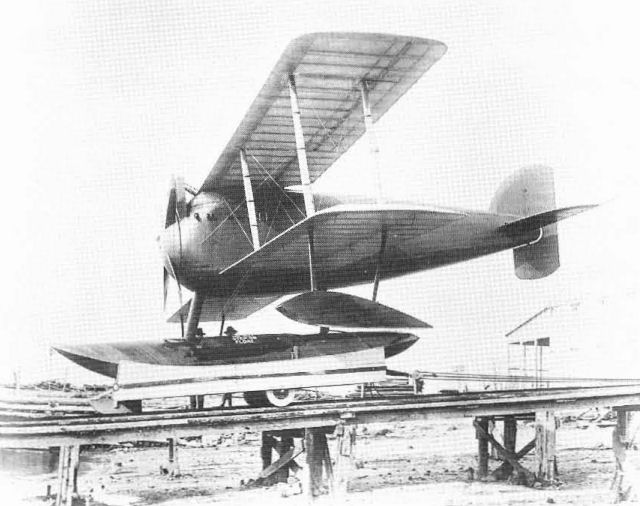
The first HA was excessively tail heavy and crashed on its first night.
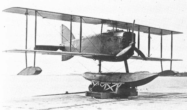
The HA·2 differed from the HA-1 mainly in wing and engine cowling detail.
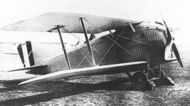
The HA was tested on wheels as a mail plane. The short wings were unsatisfaclory and two-bay wings of the HA-2 type were installed on the three sold to the US Post Office.
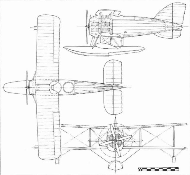
Model HA-1.
Janin Patent Boat
This aeroplane was unique in that it was built solely to prove that it would not fly. In 1917, Curtiss was involved in a continuation of the Janin patent infringement suit, To prove that the Janin patent was unworkable and should therefore be invalidated, Curtiss built a twin-engine flying-boat that was conventional in all respects except in the areas affected by Janin's patent. The special flying-boat, completed early in 1918, proved Curtiss's points of contention but the patent suit was not settled in Curtiss's favour until after the war.
This aeroplane was unique in that it was built solely to prove that it would not fly. In 1917, Curtiss was involved in a continuation of the Janin patent infringement suit, To prove that the Janin patent was unworkable and should therefore be invalidated, Curtiss built a twin-engine flying-boat that was conventional in all respects except in the areas affected by Janin's patent. The special flying-boat, completed early in 1918, proved Curtiss's points of contention but the patent suit was not settled in Curtiss's favour until after the war.
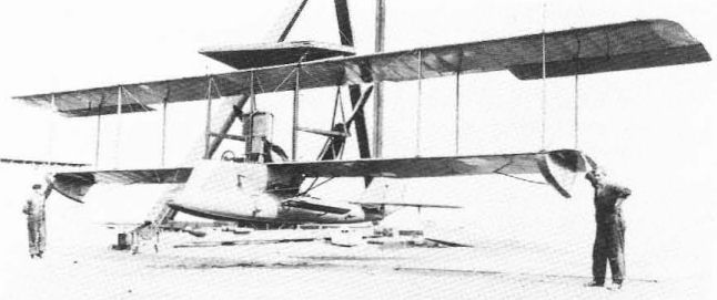
The Janin Patent Boat of 1918 was built to prove that the flying-boat patent issued to Albert Janin was unworkable.
Model MF (Model 18)
The MF was a greatly improved two-seat training flying-boat that was evolved from the Model F through the experimental BAT and BAP models. The designation stood for Modernized F. Structurally, the MF was more like the HS design than the F, but it was in the weight-power-size class of the F and was intended as a replacement for it.
A very prominent feature of the MF was the use of sponsons on each side of the forward hull as introduced on the America and used on many subsequent flying-boats. Initial powerplant was the 100 hp Curtiss OXX-3 but experimental installations were made with the 150 hp Wright-Hispano and the 150 hp Curtiss K-6, a new six-cylinder inline engine that was essentially half of the 400 hp K-12 developed for Curtiss by Charles Kirkham.
Curtiss built six MFs at Garden City on one Navy order and sixteen of 47 on a second order that was cancelled by the Armistice. The Navy built 80 more in the Naval Aircraft Factory at a cost of $5,821 each less engine for the first 20 and $3,771 each for the last 20. After the war, Curtiss continued limited production of the MF for the civil market under the name of Seagull and also converted former Naval MFs to Seagulls for civil use. Other Curtiss and Navy-built MFs that became surplus were acquired by the Cox-Klemin Aircraft Co of College Point, Long Island, which rebuilt them for the civil market in the early 1920s.
MF
Trainer flying-boat. Two pilots. 100 hp Curtiss OXX-3.
Span 49 ft 9 in (15,16 m); length 28 ft 10 in (8,78 m); height 11 ft 7 in (3,53 m): wing area 402 sq ft (37,34 sq m).
Empty weight 1,850 lb (839 kg); gross weight 2,488 lb (1,128 kg).
Maximum speed 72 mph (115,87 km/h); climb 2.400 ft (731 m) in 10 min: service ceiling 4,100 ft (1,250 m); range 345 miles (555 km).
Model 18 - Seagull
This was a refurbished wartime MF Navy flying-boat sold commercially in 1920. In spite of such improvements as the 160 hp Curtiss C-6 engine, sales were poor, approximately 16, because of direct competition from surplus Navy models and from other firms that offered their own rebuilt versions of the MF. Technical data as for MF except:
Empty weight 1,191 lb (540 kg); gross weight 2,726 lb (1,236 kg). Maximum speed 76.5 mph (123.11 km/h); cruising speed 60 mph (96.55 km/h); climb 260 ft/min (1.32 m/sec); service ceiling 5,900 ft (1,798 m); range 288 miles (463 km).
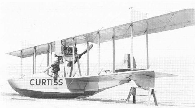
The MF was the production version of the Model BAP and the letters stood for Modernized F. The Naval Aircraft Factory also built MFs.

The Curtiss Seagull was a civil version of the wartime MF flying-boat fitted with the 160 hp Curtiss C-6 engine.
The NC Boats (Model 12)
The famous NC flying-boats were the result of a design co-operation between the US Navy and Curtiss, hence the designation NC. As the JN designation became Jenny, so the NC became Nancy but while that term was used in contemporary times, it soon died; the fame of the NC series rests on the accomplishments of a single example, the NC-4, the first aeroplane to fly across the Atlantic ocean.
The concept of the NC boats originated with Rear Admiral David W. Taylor, Chief of the Navy's Bureau of Construction and Repair, who was concerned about aeroplanes en route to France by ship being lost to German submarines. He thought that aeroplanes should be developed that could fly across and be ready for duty on arrival. Navy engineers led by Commanders G. Conrad Westervelt and Jerome Hunsaker began design studies in September 1917.
As the only experienced builder of large flying-boats in America, Glenn Curtiss was called to Washington for consultation. He returned to Buffalo and was back in a few days with two versions of a short-hull flying-boat with a wingspan of 140 ft (42,67 m). One had five of the Navy's new 360 hp Liberty engines and the other had three. The short hull was primarily a weight-saving device; Curtiss had previous experience with the type on the earliest flying-boats and the BT of 1916. Curtiss's original designation for the design was TH-1, for Taylor-Hunsaker.
Taylor's group chose the three-engined design and Commander Holden C. Richardson was called in to do the detail design of the hull. Curtiss was to design the wings, empennage, and other details, finally receiving a contract for this work on 24 November. In December, it was decided to give Curtiss a contract to build four of the new flying-boats. Later, the new Naval Aircraft Factory was ordered to build six more.
No official designation for the new type existed at the time. Suggestions to call it DWT for Admiral Taylor were vetoed and Curtiss's TH-1 was not adopted because the Navy felt that it was primarily a Navy, not a Curtiss, project. The final NC for Navy-Curtiss was a logical compromise.
Virtual flying ships, the NCs followed the Naval custom of numbering the individual ships within a class. The assigned designations of NC-1 to NC-4 were not separate model numbers; they were individual aeroplane numbers for NC-class aeroplanes. Like series-built ships, the NCs showed individual differences as a result of construction experience and different approaches to design problems, particularly powerplant arrangement. Two official variations of the NC designation appeared in 1919: NC-T - a configuration using four tandem-pair engines in two nacelles, applied only to NC-2, and NC-TA - four-engined aircraft configured in the modified form of NC-1 and equipped for the transatlantic flight of May 1919.
Under the revised Naval designation system of 1923, all the NCs became P2N-1 for the Navy's second palrol design, at least on paper. The original designations remained in common use.
With the Buffalo plant expanding for large-scale production, Curtiss's design work on the experimental NCs got low priority from the new management. Not until the project was transferred to the new Experimental plant at Garden City did work really get under way although construction of NC-1 had started in Buffalo in December 1917.
The existing Curtiss Garden City plant was too small for such an enormous construction job, so the Navy built a greatly enlarged shop area there. It also built a new hangar capable of housing two assembled NCs at the Rockaway Naval Air Station, 20 miles (32 km) from Garden City. The NCs were first assembled at the factory, then dismantled, trucked to Rockaway, and reassembled for flight there.
Curtiss also had a manpower problem. All available skilled help was already employed in other aircraft plants in the New York area, so most of the actual construction of the NCs was farmed out to established boat builders and woodworking firms in the New England area. After the first four NCs were completed, Peter Jannsen, the Garden City shop manager, was hired by the Navy to supervise construction of the final six at the Naval Aircraft Factory. Average cost of the NC boats, less GFE, was $125,000.
The war ended soon after completion of NC-1 and the requirement for transatlantic delivery vanished. For a while, it looked as if the remaining NCs would be cancelled. However, with other nations preparing to go after the renewed Daily Mail prize for the first transatlantic flight, the Navy decided to be the first to make the crossing - not for the money but for the prestige of the US Navy. The project received official status on 4 February, 1919.
Briefly, the plan was to use NC-1, 3 and 4, collectively known as Seaplane Division One, departing from Rockaway for Trepassy Bay, Newfoundland, 950 miles (1,529 km) away, in May. From there, there was a nonstop flight of 1,381 miles (2.222 km) to Horta in the Azores, a short 169-mile (272 km) hop to Ponta Delgada, then a 925-mile (1,489 km) leg to Lisbon and a 500-mile (805 km) leg lo Plymouth.
Commissioning ceremonies were held at Rockaway on 3 May, and the three departed for Trepassy on 8 May, with departure for the Azores scheduled for 16 May. A string of Navy ships was stationed along the route to provide radio communication and necessary emergency assistance. Due mainly to the problems of navigating in fog, only NC-4 completed the record 3,925-mile (6,317 km) trip, reaching Plymouth on 31 May.
NC-1 - The NC-1 (serial A2291) was a tractor three-engined aircraft powered with the 360 hp low-compression Navy version of the Liberty. Each engine was in an individual nacelle and all were at the same level and in line with each other longitudinally. Pilot and co-pilot were in a cockpit in the centre engine nacelle and a gunner was located in a nest on the upper wing above the centre engine. Other gun stations were in the extreme bow and near the rear of the hull.
The NC-1 had the only Curtiss-built hull; the wings, with the now-traditional RAF 6 aerofoil, were built by the Locke Body Company of New York City, a builder of car bodies. The first flight, with Commander Richardson as pilot, was made on 4 October, 1918. On 27 November, NC-1 carried a record load of 50 passengers and crew plus one stowaway.
Test results showed that the three-engined NC-1 could not lift enough fuel for the transatlantic flight, so an extra engine was added. This was accomplished by raising the centre nacelle and modifying it to accommodate two engines in tandem. To prevent tail-heaviness from the new rear engine, the centre forward engine was moved ahead of the unchanged side engines. The pilots were relocated from the nacelle to a conventional side-by-side cockpit in the forward hull.
On the transatlantic flight, NC-1 alighted at sea short of the Azores; the crew was taken aboard a ship and the flying-boat was sunk.
NC-2 - As launched on 3 February, 1919, NC-2 (serial A2292) was a three-engined aircraft differing from NC-1 in having the centre engine installed as a pusher. The pilots rode in the front of the centre nacelle. With no centre tractor propeller between them, the side nacelles were closer together than on NC-1. This fact complicated the subsequent conversion to four engines - the revised NC-1 arrangement could not be used without the major structural work of moving the side nacelles further outboard. The problem was solved by arranging the engines in two tandem pairs in the side nacelles, hence the NC-T designation. The pilots remained briefly in the now engineless centre nacelle, which was later removed in favour of a conventional cockpit in the hull. The hull was built by Lawley & Sons, boat builders of Boston. The NC-2 was wrecked when blown ashore in a storm and parts were used on the other three NCs.
NC-3 - The construction of NC-3 (serial A2293) was far enough behind NC-1 to benefit from its test and modification programme. As launched and flown on 23 April, it duplicated the four-engined NC-1 pattern and was the first NC-TA built as such. Like NC-2, NC-3's hull was built by Lawley. NC-3 was chosen by Commander John H. Towers, commander of the flight, to be his flagship. It made a precautionary alighting at sea some 200 miles (322 km) short of the Azores. Unable to take-off again, it taxied to Horta.
NC-4 - The NC-4 (serial A2294), with hull built by the Herrescholl Company of Bristol, Rhode Island, duplicated NC-3 and was launched on 30 April. Under the command of Lt-Commander A. C. Read, it departed with the others for Trepassy, but was forced down by engine trouble and taxied 60 miles (96 km) to the Naval Air Station at Chatham, Mass. Following an engine change, it arrived at Trepassy on 10 May.
After an uneventful flight of 19 hr 23 min, NC-4 reached Horta on 17 May. It then made the short flight to Ponta Delgada to wait for word from the missing NC-1 and NC-3. It arrived in Lisbon on 27 May and reached Plymouth on 31 May after an emergency stop at Mondego in Portugal, just north of Lisbon and an overnight stop at Ferrol in Spain, due to the delay.
The hull of NC-4 was put on display in the Smithsonian Institution. In 1969 the entire machine was rebuilt for outdoor display in Washington on the 50th anniversary of the flight. It is now to be seen fully assembled in the Naval Aviation Museum at Pensacola, Florida.
NC Flying-boats
Long-range flying-boat. Five crew. Three 400 hp Liberty 12A (NC-2), four 400 hp Liberty 12A (NC-4).
Span 126 ft (38,4 m); length 68 ft 3 in (20,8 m) NC-2, 68 ft 2 in (20,77 m) NC-4; height 24 ft 5 in (7,44 m); wing area 2,441 sq ft (226,76 sq m).
Empty weight 14,100 lb (6,396 kg) NC-2, 16,000 lb (7,257 kg) NC-4; gross weight 23,000 lb (10,433 kg) NC-2, 28,000 lb (12,700 kg) NC-4.
Maximum speed 85 mph (136,79 km/h); climb in 10 min - 2,200 ft (670 m) NC-2, 2,000 ft (610 m) NC-4; service ceiling 4,500 ft (1,372 m) NC-2, 2,500 ft (762 m) NC-4; endurance 14,8 hr at cruising speed.
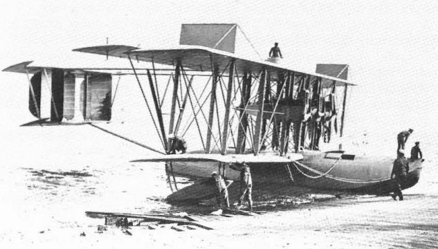
The NC-1 in its original three-engined configuration with upper wing gunner's position.

The NC-2 was also three·engined, but with the centre engine installed as a pusher and the pilots' seats in the forward part of the centre nacelle.
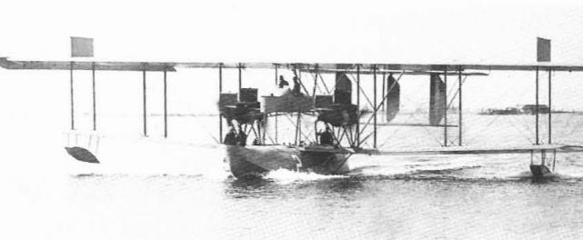
NC-2 was converted to have four engines in two tandem nacelles. The control nacelle in the centre was soon eliminated in favour of a conventional pilots' cockpit.

NC-3 and NC-4 were completed in the four-engined configuration of the modified NC-1. NC-4, illustrated, made the first aerial crossing of the Atlantic in May 1919.
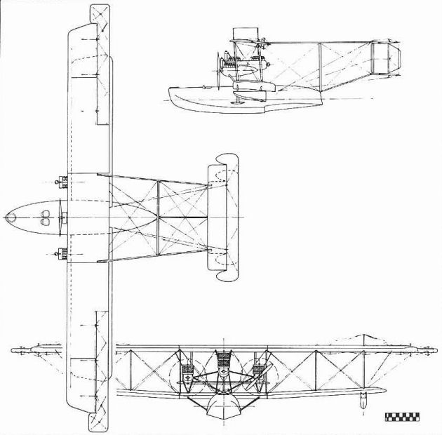
The NC-4.
Model 19 - Eagle
The Eagle was a 1919 effort to produce a potential airliner for the anticipated postwar aviation boom that never materialized. Also designed by Gilmore, the Eagle used essentially the structural concept of the earlier Oriole expanded to airliner size.
Many innovations were incorporated. Six to eight passengers were seated in a properly-designed cabin with adequate windows and built-in conveniences. The two pilots were also within the cabin, a distinct departure from the converted wartime bombers and Navy flying-boats then in use as passenger carriers. A bogie type undercarriage was used, featuring two sets of tandem wheels. An unusual feature of this gear was the use of a large streamlined metal fairing to cover most of each wheel, anticipating the use of the speed-enhancing pants that came into use in 1930.
Three-engined Eagle - The first Eagle was built as a trimotor powered with 150 hp Curtiss K-6 engines and the few production models used these or the 160 hp C-6.
Twin-engined Eagle - One twin-engined Eagle, powered with 400 hp Curtiss C-12s, was built. After the near loss of this version on its first flight due to loss of power on one engine at take-off, it was decided that 800 hp was too much for the Eagle airframe.
Single-engined Eagle - A single-engined version was developed to use the 400 hp wartime Liberty engine. The US Army Air Service bought three of these for ambulance and personnel transport work and assigned Army serial numbers 64241-64243.
Eagle I
Transport. Two pilots and six passengers. Three 150 hp Curtiss K-6 or three 160 hp Curtiss C-6.
Span 61 ft 4 in (18.69 m); length 36 ft 9 in (11.2 m); height 12 ft 4 in (3.75 m); wing area 900 sq ft (83.61 sq m).
Empty weight 5.130 lb (2.327 kg): gross weight 7.450 lb (3.379 kg).
Maximum speed 107 mph (172.19 km h); climb in 10 min 4,075 ft (1.242 m): range 475 miles (764 km).
Eagle II
Transport. Two pilots and six passengers. Two 400 hp Curtiss C-12.
Span 64 ft 4 1/8 in (19.61 m): length 36 ft 7 in (11.15 m); height 12 ft 11 in (3.93 m); wing area 937 sq ft (87.04 sq m).
Empty weight 5,310 lb (2,408 kg); gross weight 8,690 lb (3,942 kg).
Maximum speed 124 mph (199.55 km/h); range 750 miles (1,207 km).
Eagle III
Transport. Pilot and nine passengers. One 400 hp Liberty 12.
Span 64 ft 4 1/8 in (19.61 m); length 37 ft 2 9/16 in (11.34 m); height 13 ft 6 1/16 in (4.11m); wing area 937 sq ft (87.04 sq m).
Empty weight 4,245 lb (1.925 kg): gross weight 7,425 lb (3,368 kg).
Maximum speed 100 mph (160.93 km/h); climb in 10 min - 5.000 ft (1.524 m).
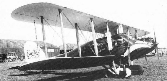
The first Curtiss Eagle was a three-engined transport with 150 hp Curtiss K-6.

The second Eagle had two 400 hp Curtiss C-12 engines but made only one flight in that configuration.

The US Army bought three Eagles each fitted with single 400 hp Liberty engines. This one was specially equipped as an ambulance.
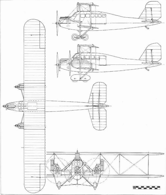
Single- and three-engined Eagle.
Model 17 - Oriole
The Oriole, also called Experimental 519 and Design L-72, was a new three-seat light commercial and sports aeroplane developed early in 1919 for the mass market that the aircraft industry optimistically expected to blossom right after the war. The Oriole was also the first of the new production Curtiss aeroplanes to be marketed under a bird's name rather than a model number, as was to be the Curtiss custom into the 1930s.
The first Oriole appeared in June 1919 and early sales seemed to bear out the builder’s optimistic expectations even at the price of $9,850. Unfortunately, as war-surplus models came on the market, their enormous price advantage easily overcame the appeal of the Oriole’s improvements and production was soon terminated. In 1921, Curtiss slashed prices to $3,000 for new OX-5 powered Orioles and $4,800 for the C-6 models to clear them out of the factory.
The Oriole was still a significant design, however. Its seating arrangement, pilot in the rear cockpit and two passengers sitting side by side in the front, with their entrance enhanced by anchoring the centre section struts ahead of the cockpit and adding a small door at the side, became the standard for practically all American three-seat biplanes built up to the mid-1930s. To achieve comfortable shoulder room without widening the fuselage unnecessarily, the front seats of the Oriole were staggered slightly. The added luxury of an electric starter, advertized as a standard feature of the Oriole, was an innovation that did not catch on with other light commercial aeroplanes for many years.
Designed by William Gilmore, the Oriole had the laminated wood veneer fuselage of the 1918 Model 18s and very JN-like two-bay wings with traditional thin aerofoil. Early Orioles were fitted with the surplus Curtiss OX-5 engine but this was quickly replaced with the 150 hp Curtiss K-6 and the 160 hp C-6. Even with this increased power the performance was short of expectations so the wing span was increased from the original 36 ft (10.97 m) to 40 ft (12.19 m). Long-wing Orioles can be recognized by the outward slope of the inner interplane struts and the rounded wingtips; the short-wing model had vertical struts and square wingtips.
Although faring poorly in sales, the Oriole achieved a degree of fame at the hands of Curtiss test pilot C. S. ‘Casey’ Jones, who won numerous prizes in early postwar air races with his personal model. He constantly refined this and it ended up with clipped wings and revised strutting.
The exact number of Orioles built is unknown and only a few survived to 1927 when US civil aircraft were required to be licensed. Although never issued an Approved Type Certificate, some Orioles were licensed for commercial operation after 1927 on the basis of individual aircraft inspection.
Oriole (short-span)
Utility aircraft. Pilot and two passengers. 90 hp Curtiss OX-5.
Span 36 ft (10.97 m): length 25 ft (7.62 m): height 10 ft 1 in (3.07 m): wing area 326 sq ft (30.28 sq m).
Empty weight 1.428 lb (648 kg): gross weight 2,036 lb (923 kg).
Maximum speed 86.3 mph (138.88 km/h); cruising speed 69 mph (111.04 km h): initial climb 500 ft min (2.54 m sec): service ceiling 8.000 ft (2.438 m); range 582 miles (937 km).
Oriole (long-span)
Utility aircraft. Pilot and two passengers. 160 hp Curtiss C-6.
Span 40 ft (1219 m): length 26 ft 1 in (7.95 m): height 10 ft 3 in (312 m): wing area 399 sq ft (37.06 sq m).
Empty weight 1,732 lb (786 kg): gross weight 2,545 lb (1.154 kg).
Maximum speed 97 mph (156.1 km/h); cruising speed 77.6 mph (124.88 km/h); initial climb 700 ft/min (3.55 m sec): service ceiling 12,850 ft (3,917 m); range 388 miles (624 km).
Oriole conversions
With the supply of cheap war-surplus aeroplanes exhausted by 1925, two firms sought to undercut the price of entirely new machines by fitting available components of unfinished short-wing Curtiss Orioles to new structure.
Curtiss-Ireland Comet-Mr G. S. Ireland, a Curtiss salesman at the time, acquired a supply of Oriole fuselages and obtained the assistance of Curtiss engineers in developing new wings for them. These used a later thick aerofoil, had the same 36-ft span but an area of 366 sq ft (34 sq m), and required only one bay of struts. This improvement raised the top speed to 99 mph (159.32 km/h) with the OX-5 engine and allowed a gross weight increase to 2,163 lb (981 kg). Alternate engines were the 150-160 hp Curtiss K-6 and C-6 and the 150-180 hp Wright-Hispano A, I, and E.
To produce this hybrid that he named Comet, Ireland established a small plant near the Curtiss Garden City factory. While the Curtiss company had nothing to do with the Comet, enough examples appeared in subsequent records as Curtiss-Ireland to establish a Curtiss identity.
Pitcairn Orowing - Harold Pitcairn, later of autogyro fame, established his own firm in 1923. In 1925 he took the opposite course to Ireland and fitted short-span Oriole wings, tail surfaces, and undercarriage to a new light-weight three-seat steel-tube fuselage and marketed the result as the Pitcairn PA-2 Orowing in open acknowledgement of the origin of the wings.
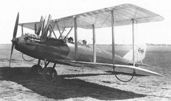
Big sales were expected for the OX-5 powered Oriole after World War I, but the new design could not compete with cheap surplus models using the same engine.
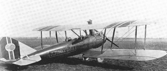
Performance of the Oriole was improved by installing the 160 hp Curtiss C-6 engine and increasing the wing span by four feet. Earlier model did not have the sloping inner struts and rounded wingtips.
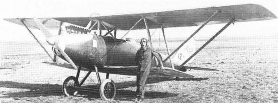
Orioles with clipped wings and uprated engines did well in stockplane races of the early 1920s. This one, flown by Curtiss Flying Service manager ‘Casey’ Jones, introduced the wing surface radiators developed by Curtiss in 1922.
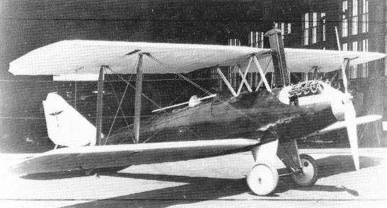
The Ireland Comet, erroneously referred to as Curtiss-Ireland Comet, was a short-wing Oriole with OX-5 engine fitted with new wings by G.S. Ireland in 1925. The wing roots were thinned to mate with the original Oriole fuselage and centre-section fittings.
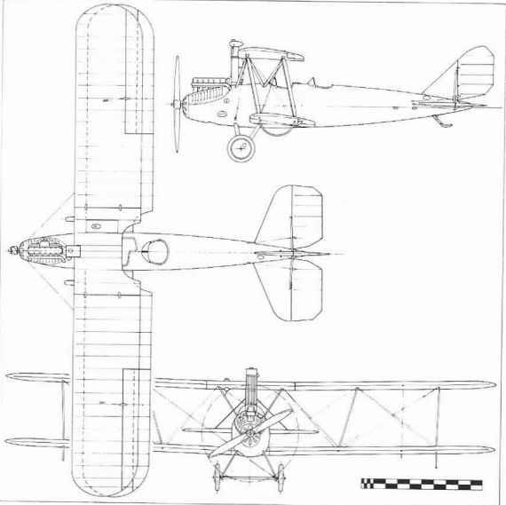
Model 17 - Oriole
Bristol Fighter
<...>
Following several serious crashes of early test models, the Curtiss contract was cancelled after 26 Bristols had been completed (US Army serial numbers 34232/34257). This did not kill off official US interest in the design, however. While Curtiss tried to develop its own version of a Bristol replacement, the CB, the Air Service Engmeenng Division at McCook Field developed lower-powered versions with 300 hp Wright-Hispano engines and new laminated wood monocoque fuselages. Thirty of these were eventually produced by the Dayton-Wright Aircraft Company under the designation of USXB-1A.
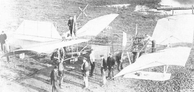
The Langley Aerodrome of 1903 as restored by Curtiss in 1914 with its original powerplant and propellers but with Curtiss-built pontoons.
Loening-Milling Tractor Biplane. Late in 1914, when the Army's pusher-type trainers were proving so unreliable, the Army's civilian engineer Grover C. Loening and Army Lt T. D. Milling jointly designed a new tractor biplane that was structurally and aerodynamically far behind the earlier Curtiss Models J and N. Since this was designed at North Island, Loening and Milling arranged for Curtiss to build it in his North Island factory.
The work was done largely by Curtiss students and the tractor was delivered on 30 December. It was unacceptable and was not purchased by the Army.
The work was done largely by Curtiss students and the tractor was delivered on 30 December. It was unacceptable and was not purchased by the Army.
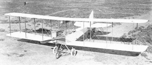
The Loening-Milling biplane was not a Curtiss design but was built in the Curtiss shops at North Island and filled with a Curtiss Model S engine.
Model 26 - Orenco D
In 1918, the Army bought four examples of an experimental fighter developed by the Ordnance Engineering Co (Orenco) of Baldwin, NY. This design, Orenco's Model D, proved desirable as a production model for the postwar Air Service, so the Army, which owned the design under prevailing policies, invited bids from the industry for a lot of 50. Curtiss won the order; Orenco was unable to sell other designs and soon shut down.
The Orenco D, modified only slightly by Curtiss to have a longer upper wing and horn-balanced ailerons, was an all-wood single-seater featuring a ply-covered fuselage and the American version of the 300 hp French Hispano-Suiza engine built by Wright as its Model H. It was, in fact, the only single-seat fighter with plywood fuselage ever to serve in the Army. Some were diverted to test work with French Lamblin 'Pineapple' radiators and turbo-superchargers, but the nose radiator installation of the prototypes was standard.
Orenco D
Single-seat Pursuit. 300 hp Wright-Hispano H.
Span 33 ft (10.05 m); length 21 ft 51 in (6.54 m); height 8 ft 4 in (2,53 m); wing area 273 sq ft (25,36 sq m).
Empty weight 1,908 Ib (865 kg); gross weight 2,820 Ib (1,279 kg).
Maximum speed 139 mph (223.69 km/h); cruising speed 133 mph (214 km/h); climb 1,140
ft/min (5,79 m/sec); service ceiling 12,450 ft (3,795 m); range 340 miles (547 km).
Armament - two .30-in Browning machine-guns.
US Army serial numbers: 40107/40110 (Orenco), 63281/63330 (Curtiss)
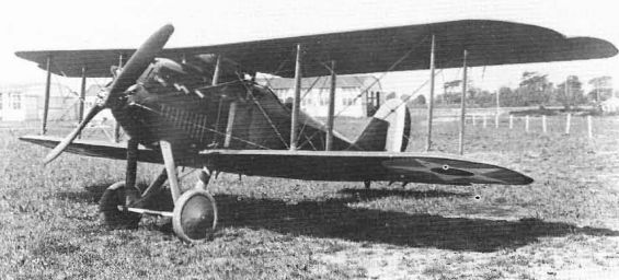
Curtiss won the 1920 order for fifty production models of the Orenco Model D that had been developed by the Ordnance Engineering Company in 1918.
Miscellaneous Aeroplanes, 1910-14
In addition to the principal pusher and flying-boat designs, Curtiss produced others within this period. While not all were designed by Curtiss, their construction provided additional experience.
Pfitzner Monoplane. Late in 1909, Alexander L. Pfitzner, who occasionally helped Curtiss with powerplant problems, undertook the building of a monoplane of his own design in the Curtiss shops at his own expense, although Curtiss employees built some of the parts. While it owed much to the layout of the contemporary Curtiss biplane, it had one unique feature. Mindful of the Wrights, Pfitzner achieved lateral control by means of telescoping wingtips, extending one tip to increase the lift on that side.
Pfitzner's monoplane was barely successful, flying on 21 December, 1909, but it did earn him the distinction of flying the first American monoplane.
Rebuilt Standard
Among the surplus aeroplanes that Curtiss bought from the US Government in 1919 were numerous model J-1s designed by the Standard Aero Corporation. These were also built under licence by the Fisher Body Division of General Motors, Wright-Martin, and Dayton-Wright. Since one of the major deficiencies of this model was the original 100 hp Hall-Scott A-7A engine, Curtiss reconditioned the J-1s to nearly-new and sold them for $3,500, approximately half the cost of a new machine. Wing area varied depending on whether the original ailerons or larger ones built by Curtiss to improve controllability were fitted.
OX-5 powered version
Trainer. Two pilots. 90 hp Curtiss OX-5.
Span 44 ft 10 21.32 in (13.68 m); length 27 ft 1 1/2 in (8.26 m): height 10 ft 4 5/8 in (3. 16m): wing area 429 sq ft (39.85 sq m).
Empty weight 1.448 lb (657 kg): gross weight 2,025 lb (918 kg).
Maximum speed 68 mph (109.43 km/h); cruising speed 54 mph (86.9 km h): climb 410 ft/min (2.08 m/sec): service ceiling 9.250 ft (2.819 m); range 344 miles (553 km).
C-6 powered version
Trainer. Two pilots. 150 hp Curtiss C-6.
Span, length and height as OX-5 version. Wing area (with large ailerons) 436 sq ft (40.5 sq m). Empty weight 1.500 lb (680 kg): gross weight 2.275 lb (1,032 kg).
Maximum speed 79.3 mph (127.61 km/h); cruising speed 63.4 mph (102.03 km/h); climb 710 ft/min (3.60 m/sec); service ceiling 9.750 ft (2.972 m): range 264 miles (425 km).

War-surplus Standard Aero Corporation Model J remodelled by Curtiss with JN-4B type nose and Curtiss OX-5 engine. The fuselage bears the former Army serial 22693 but the number on the rudder is 22677.
Goupil Duck
The odd-looking Duck of 1916-17 was the result of further Curtiss attempts to invalidate the Wright patent. The design was originated and patented in 1883 by a Frenchman, Alexander Goupil, and showed surprisingly modern lines and features. While Goupil did not build his design because of lack of a suitable powerplant, he clearly recognized the need for three axes of mechanical control. Lateral control was by means of auxiliary surfaces that functioned exactly like latter-day ailerons.
Working from Goupil's patent drawings, Curtiss Project Engineer N. W. Dalton revised the design only enough to make it structurally sound and added a conventional undercarriage in place of Goupil's skids. The Duck was powered with a Curtiss OXX engine buried in the fuselage at the centre of gravity and drove a tractor propeller through an extension shaft. Built in Buffalo, the Duck was first tried at Hammondsport on the old Langley floats. Barely able to hop off the water with their weight, it was shipped to Newport News, fitted with wheel undercarriage, and flew successfully on 19 January, 1917.
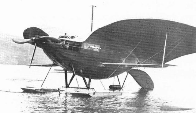
In 1916 Curtiss built this Duck from the 1883 design of Alexander Goupil in his continuing effort to invalidate the Wright patent. It was first flown as a seaplane al Hammondsport.
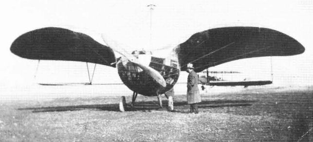
The Goupil Duck was transferred to the Curtiss facility at Newport News and continued its flights there as a landplane.