
Книги
Centennial Perspective
J.Herris
DFW Aircraft of WWI
502
J.Herris - DFW Aircraft of WWI /Centennial Perspective/ (29)

Late-production DFW C.V 4482/18 captured in the Middle East has printed camouflage fabric on all flying surfaces with the exception of the white-painted rudder. It was from the same production batch as 4475/18; both were ordered in June 1918. An F.K.8 is in the background.
DFW C.V at left and BE.2 at right in Estonian service after the war.

DFW C.V(Av) 287/18 after British cockades were painted over the German national insignia. However, the butterfly insignia was left intact. An RE.8 is in the background.
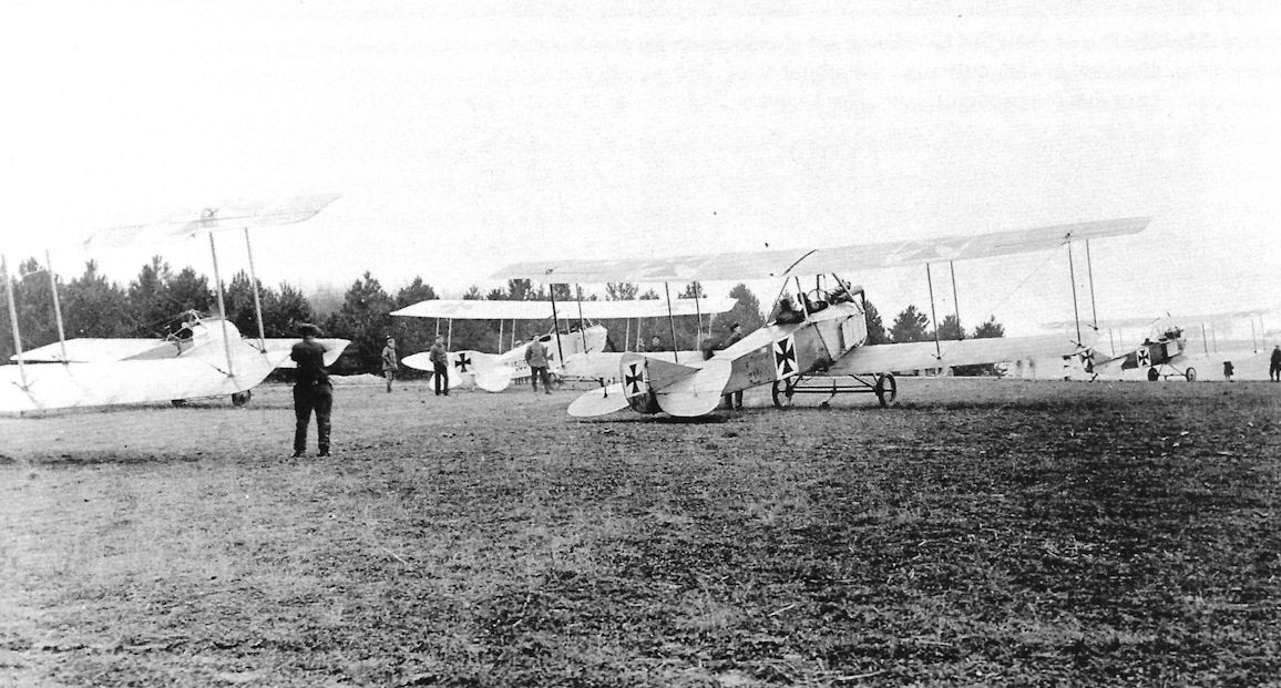
DFW C.I C.1505/15 is in the left center background in front of the Fokker Eindecker in this photo of Feld-Flieger Abteilung 61. LVG B.I and Albatros B.II aircraft form part of this motley collection. (Bruno Schmaling)

Lineup of DFW B.I trainers at the DFW flying school at Lubeck-Travemunde. The aircraft at far right is Albatros C.I C.26/15 or perhaps C.26X/15. To the left of the Albatros C.I is DFW B.I GRAF SPEE, then B.I KAISER WILHELM, B.I LUTTICH, B.I SALEM ALEIKUM, B.I TANNENBERG, B.I name illegible, B.I QUENTIN, and several other DFW B.I trainers whose names cannot be read. (Peter M. Grosz Collection/SDTB)

Early Aviatik nameplate, here from an Aviatik C.III. An identical nameplate was fastened to the front of the fuselage on licence-built DFW C.V aircraft from early Aviatik batches. ((c) Piotr Mrozowski)
DFW Mars Two-Seaters
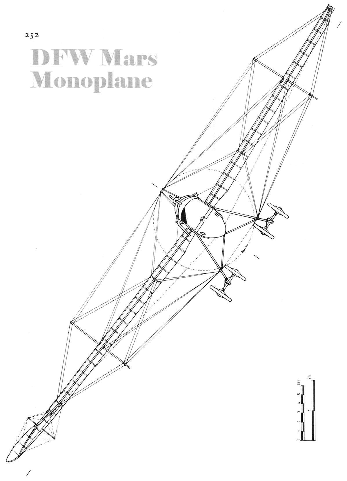
The Mars monoplane was designed and built in 1912, the same year as the Mars-Buchner biplane was built. The standard Mars biplane was developed from the Mars-Buchner biplane with a more robust wing cellule. The Mars monoplane and biplane were similar in appearance other than their wings.
The Mars monoplane originally had a four cylinder engine but most had a six-cylinder, 100 hp Argus, Daimler, or NAG engine. The wings were designed to fold. Most used wing warping for roll control although at least one had a modified wing that featured ailerons.
The Mars biplane also originally used four-cylinder engines like the 95 hp NAG, Daimler G4F, and others. Once more powerful six-cylinder engines became available the later production Mars biplanes used these more powerful engines. The wing cellule was a robust, three-and-a-half bay design that was also designed to fold the wingtips for storage in tents while in the field.
Both the Mars monoplane and biplane were two-seat aircraft that could be used for reconnaissance and training. In 1913 a Mars biplane was flown for the Turkish side in the was against Bulgaria, and a long reconnaissance flight was flown with Captain Kemal Bey, later to become president of Turkey Kemal Attaturk.
Small numbers of the Mars biplane were flown at the front during the early part of the Great War, and it is possible that Mars monoplanes were also used at the front. Certainly both types were used for training before and after the beginning of the war.
DFW Mars Specifications
Monoplane Biplane
Engine 100 hp NAG 100 hp Mercedes D.I
Span, Upper 16.8 m 17.0 m
Wing Area 35 m2 46 m2
Length 9.7 m 9 m
Height - 3.18 m
Empty Weight 560 kg 700 kg
Loaded Weight 820 kg 920 kg
Maximum Speed 120 km/h 100 km/h
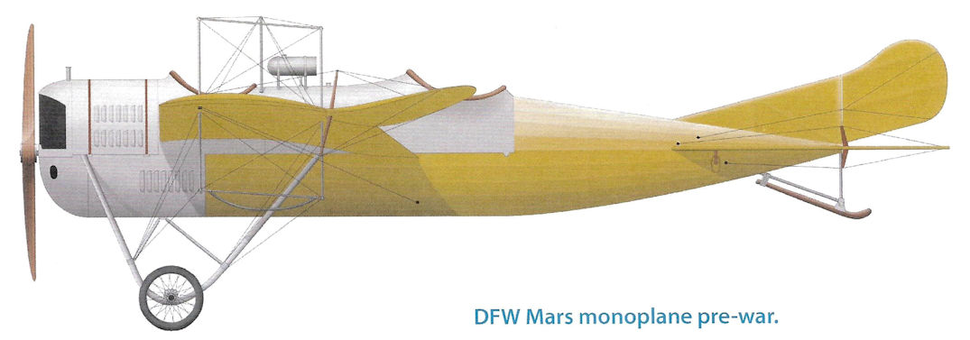
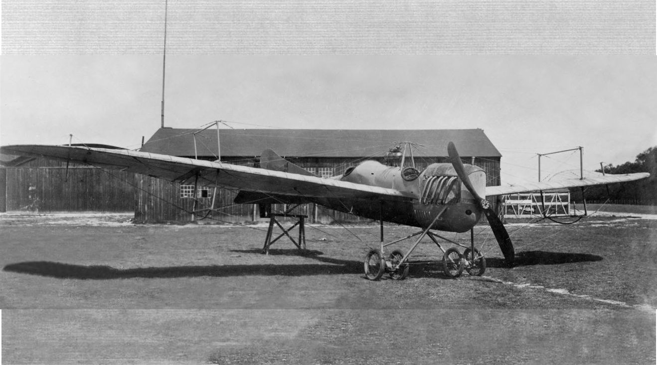
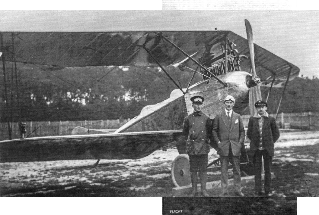
DFW Mars monoplane pre-war.
THE MILITARY COMPETITIONS. - The Mars monoplane, entered by Mr. C. E. Kny and constructed by the Deutsche Flugzeug Werke at Leipzig. It will carry the No. 23 in the Military Trials.
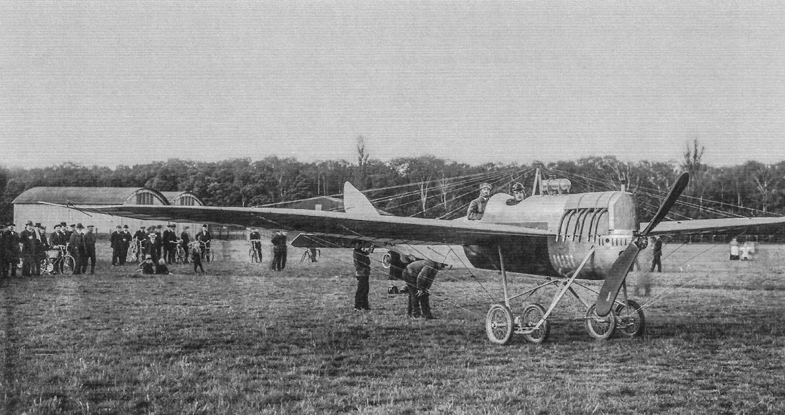
DFW Mars monoplanes powered by a six-cylinder engines; the gravity tank above the fuselage is distinctive. (Peter M. Bowers Collection/Museum of Flight)
DFW Mars monoplanes powered by a six-cylinder engines; the gravity tank above the fuselage is distinctive. (Peter M. Bowers Collection/Museum of Flight)
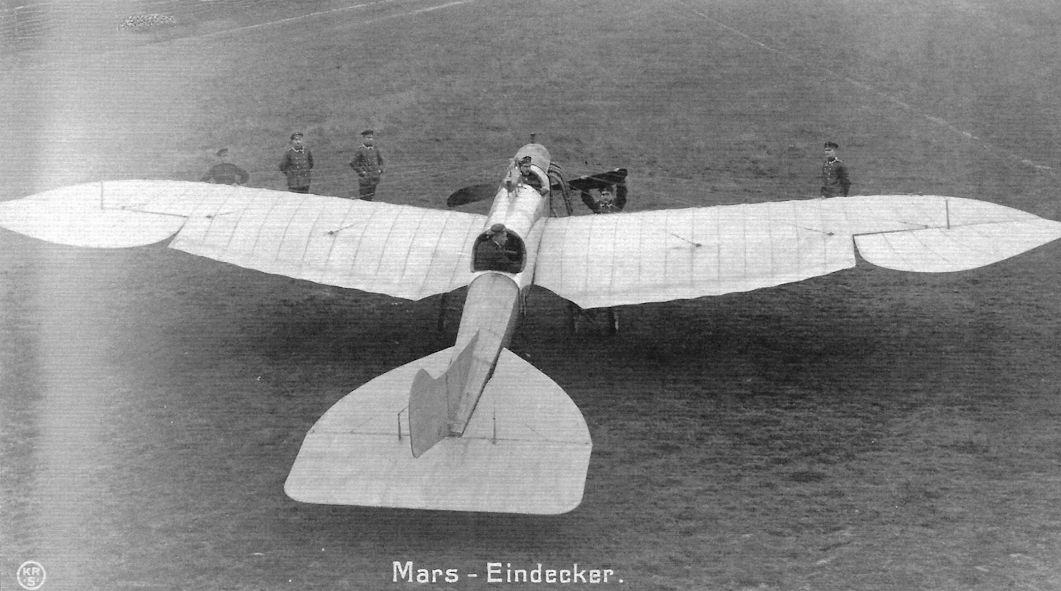
The DFW Mars monoplane had a distinctive wing planform; this one had ailerons instead of wing warping. (Peter M. Bowers Collection/Museum of Flight)
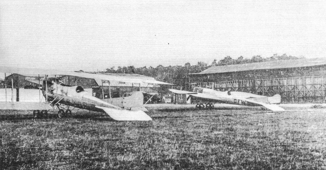
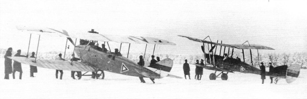
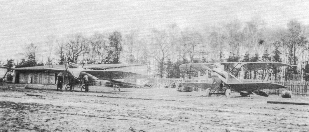
DFW Mars monoplane at right with "DFW" and Mars biplane at left. Both types were built in small numbers and used for training and reconnaissance in the opening months of the war. Their fuselage and vertical tails were very similar. (Peter M. Grosz Collection/SDTB)
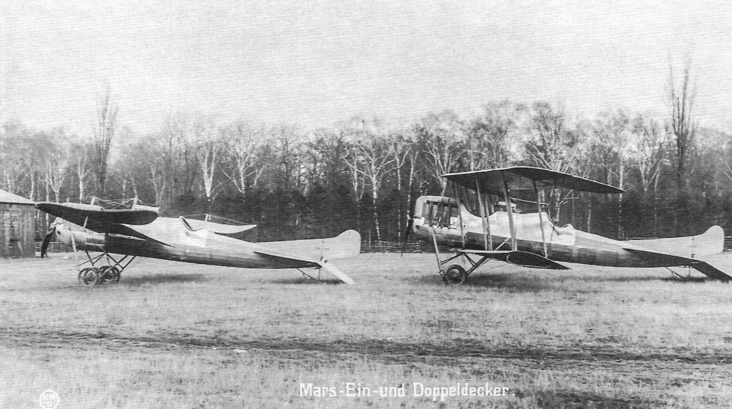
DFW Mars monoplane at left and Mars biplane at right. Both types were built in small numbers and used for training and reconnaissance in the opening months of the war. Their fuselage and vertical tails were very similar. (Peter M. Bowers Collection/Museum of Flight)
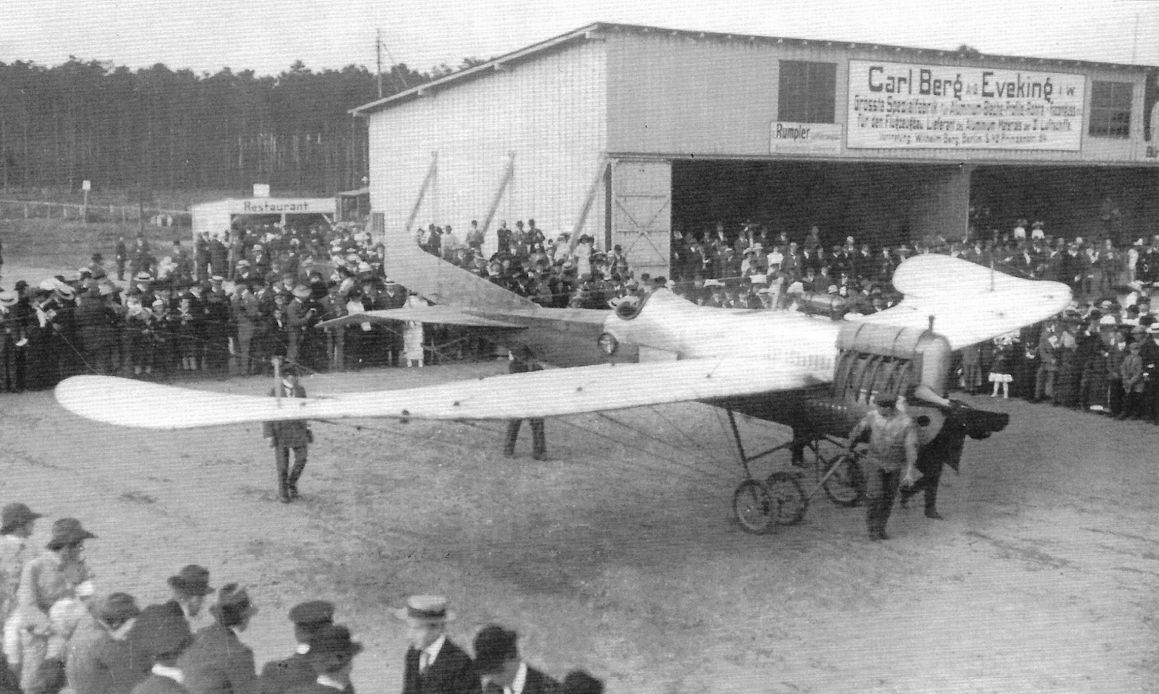
A DFW Mars monoplane at a pre-war flying exhibition. (Peter M. Grosz Collection/SDTB)
The D.F.W, monoplane on which Lieut, von Hiddesen secured the first prize in the Prince Henry Reliability Trials some time ago.
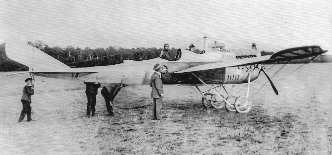
Another DFW Mars monoplane powered by a six-cylinder engine. The DFW Mars, produced in monoplane and biplane variants, was one of the miscellaneous primitive types with which Germany entered the war. These aircraft were used in small numbers during the first months of the war until replaced by more reliable aircraft of higher performance. The four-wheel undercarriage was a characteristic of the Mars monoplanes and biplanes.
Another DFW Mars monoplane powered by a six-cylinder engine. The DFW Mars, produced in monoplane and biplane variants, was one of the miscellaneous primitive types with which Germany entered the war. These aircraft were used in small numbers during the first months of the war until replaced by more reliable aircraft of higher performance. The four-wheel undercarriage was a characteristic of the Mars monoplanes and biplanes.
A DFW Mars monoplane powered by a six-cylinder engine before the war. (Peter M. Bowers Collection/Museum of Flight)
DFW Mars monoplanes powered by a six-cylinder engines; the gravity tank above the fuselage is distinctive. (Peter M. Bowers Collection/Museum of Flight)
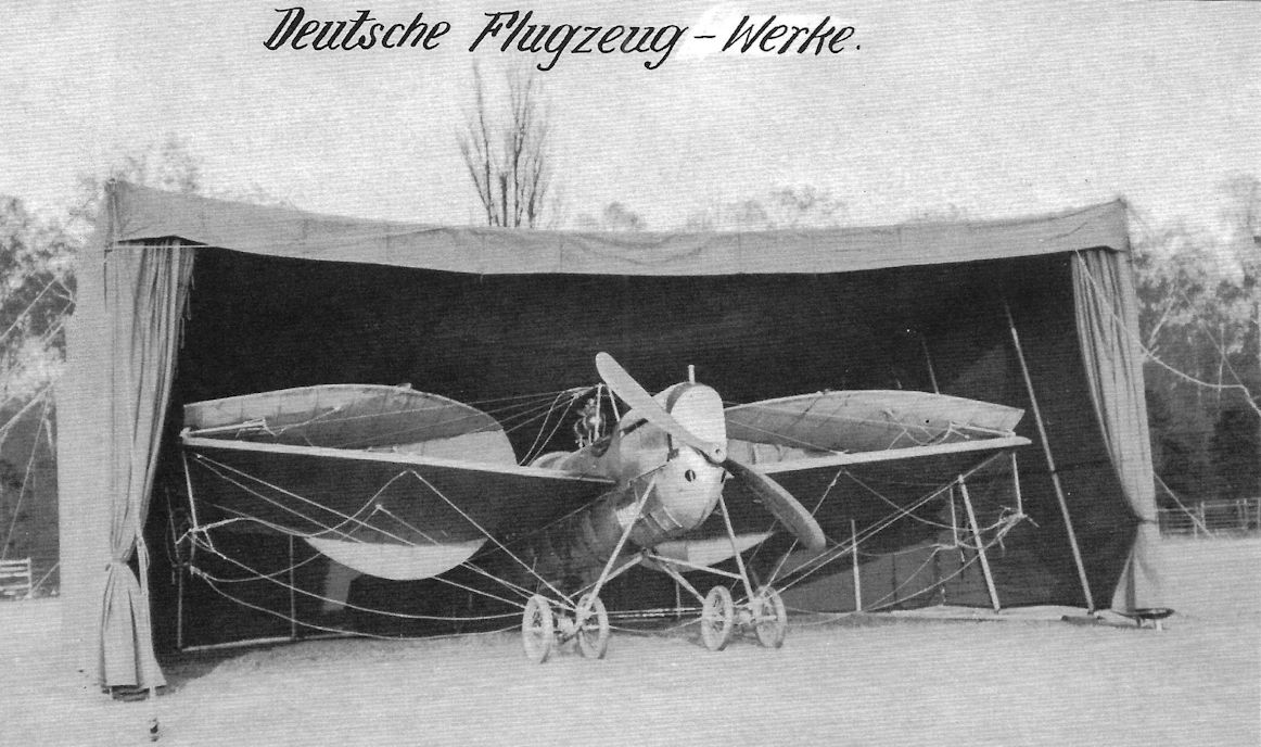
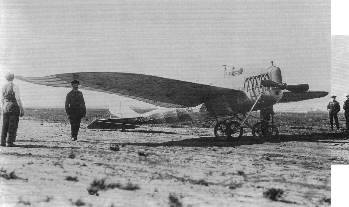
A DFW Mars monoplane demonstrates its ability to fold its wings to fit into a tent, a requirement at the time. (Peter M. Grosz Collection/SDTB)
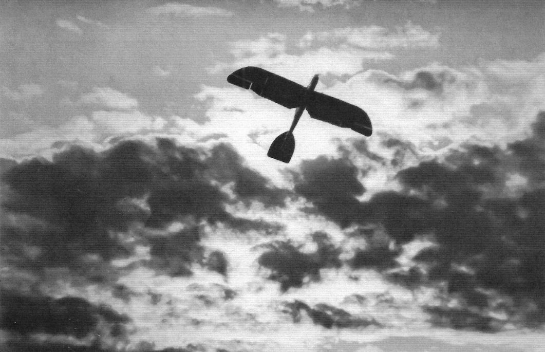
DFW Mars monoplane in flight reveals its distinctive wing and tail profiles. (Peter M. Grosz Collection/SDTB)
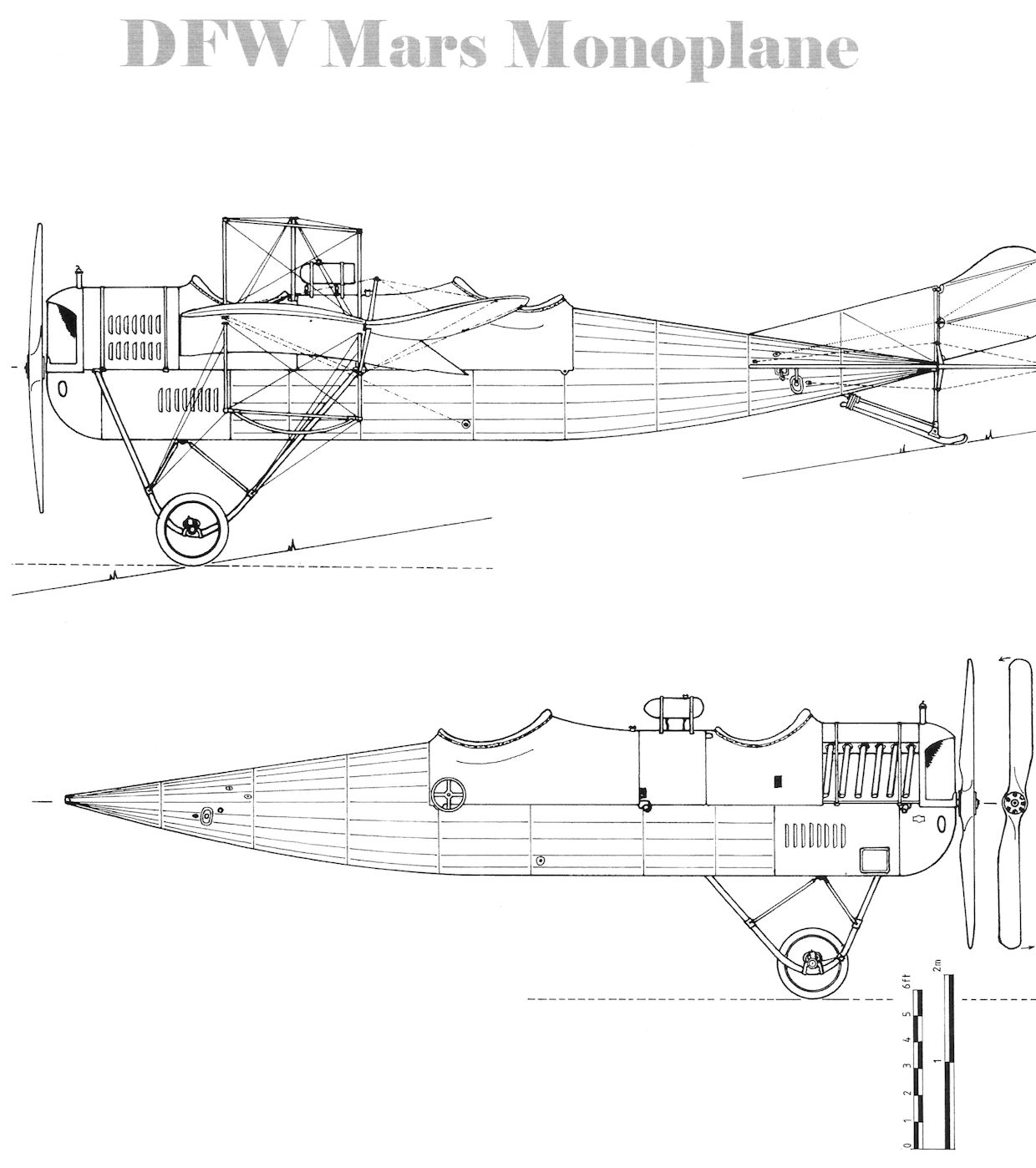
DFW Mars monoplane
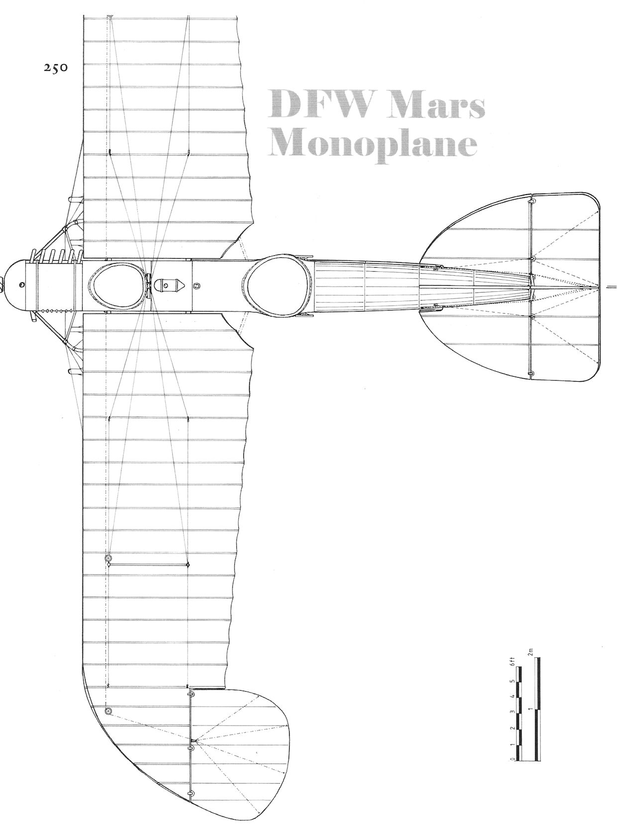
DFW Mars monoplane
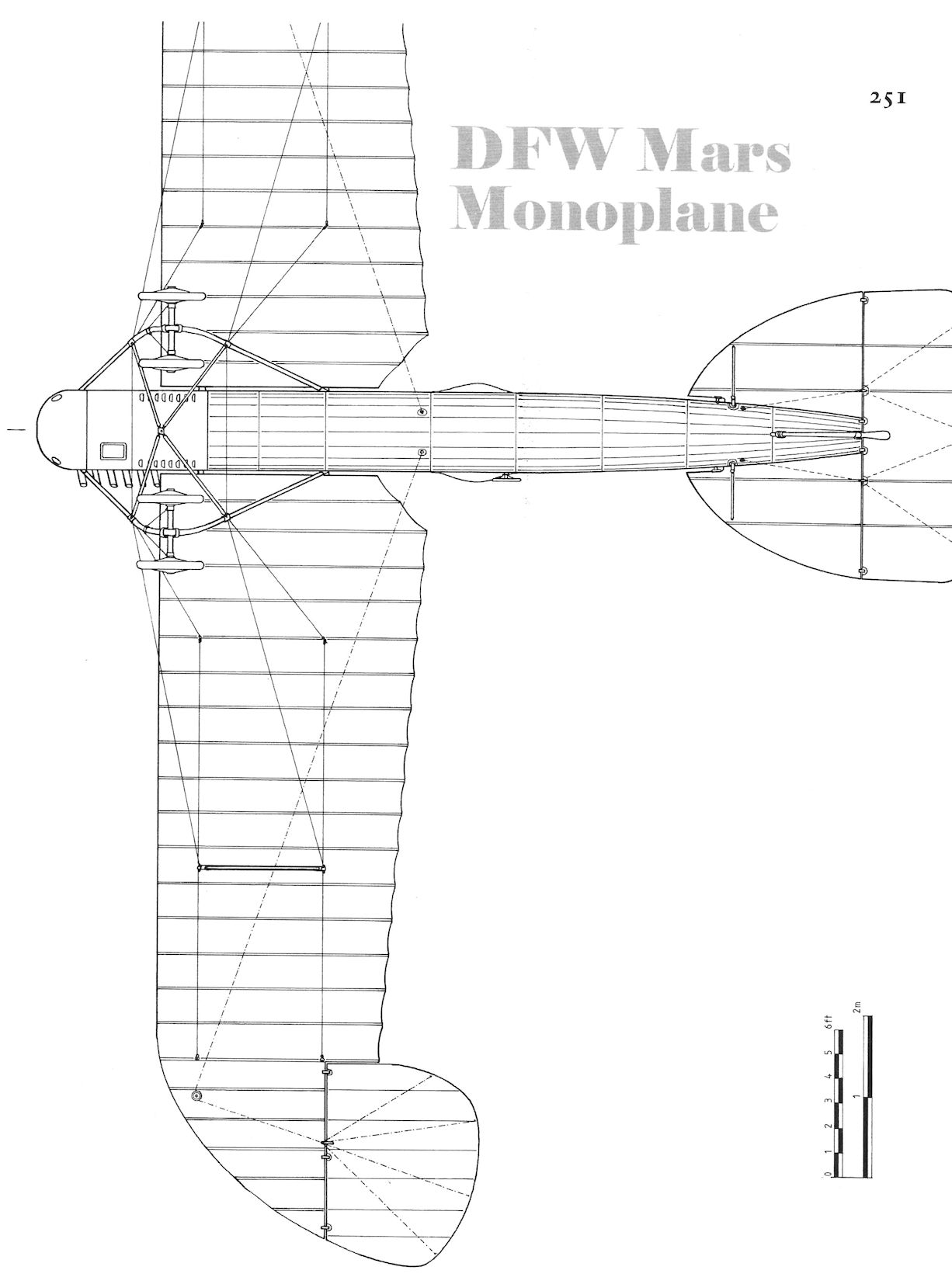
DFW Mars monoplane
DFW Mars monoplane
DFW Mars Two-Seaters
The Mars monoplane was designed and built in 1912, the same year as the Mars-Buchner biplane was built. The standard Mars biplane was developed from the Mars-Buchner biplane with a more robust wing cellule. The Mars monoplane and biplane were similar in appearance other than their wings.
The Mars monoplane originally had a four cylinder engine but most had a six-cylinder, 100 hp Argus, Daimler, or NAG engine. The wings were designed to fold. Most used wing warping for roll control although at least one had a modified wing that featured ailerons.
The Mars biplane also originally used four-cylinder engines like the 95 hp NAG, Daimler G4F, and others. Once more powerful six-cylinder engines became available the later production Mars biplanes used these more powerful engines. The wing cellule was a robust, three-and-a-half bay design that was also designed to fold the wingtips for storage in tents while in the field.
Both the Mars monoplane and biplane were two-seat aircraft that could be used for reconnaissance and training. In 1913 a Mars biplane was flown for the Turkish side in the was against Bulgaria, and a long reconnaissance flight was flown with Captain Kemal Bey, later to become president of Turkey Kemal Attaturk.
Small numbers of the Mars biplane were flown at the front during the early part of the Great War, and it is possible that Mars monoplanes were also used at the front. Certainly both types were used for training before and after the beginning of the war.
DFW Mars Specifications
Monoplane Biplane
Engine 100 hp NAG 100 hp Mercedes D.I
Span, Upper 16.8 m 17.0 m
Wing Area 35 m2 46 m2
Length 9.7 m 9 m
Height - 3.18 m
Empty Weight 560 kg 700 kg
Loaded Weight 820 kg 920 kg
Maximum Speed 120 km/h 100 km/h

DFW Mars Biplane BULLI, DFW Flying School, ca.1914.

DFW Mars Biplane DRESDEN, DFW Flying School, before the war.

DFW Mars Biplane B.88/13, unit unknown.

DFW Mars Biplane with long fin.

The DFW Mars biplanes were powered by a variety of four and six-cylinder engines such as the 95 hp NAG, etc. This later aircraft has a six-cylinder engine and two men are seated in the observer's cockpit.

An early production four-cylinder DFW Mars biplane photographed before the war in front of the Fokker hangar.

Early production DFW Mars Arrow biplanes feature different fin and rudder designs. This aircraft has a four-cylinder engine.

Ground crew and spectators surround an early four-cylinder DFW Mars biplane whose name is not quite legible. (Peter M. Bowers Collection/Museum of Flight)

Ground crew attempt to steady an early DFW Mars biplane before takeoff. The engine has four cylinders. (Peter M. Bowers Collection/Museum of Flight)

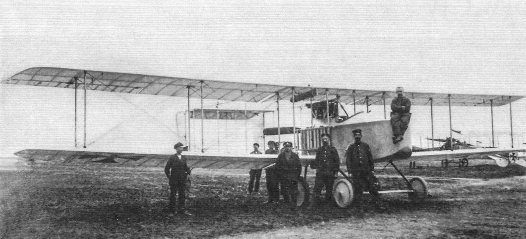
The DFW Mars biplane used as background in this group photo displays its large wingspan of 18 meters.

This DFW Mars biplane is serial B 88/13.
DFW Mars monoplane at left and Mars biplane at right. Both types were built in small numbers and used for training and reconnaissance in the opening months of the war. Their fuselage and vertical tails were very similar. (Peter M. Bowers Collection/Museum of Flight)
DFW Mars monoplane at right with "DFW" and Mars biplane at left. Both types were built in small numbers and used for training and reconnaissance in the opening months of the war. Their fuselage and vertical tails were very similar. (Peter M. Grosz Collection/SDTB)

Two DFW Mars biplanes are shown at the DFW flying school.The one in front is named BULLI. Both are carrying an early version of the German national insignia, indicating the photo was taken during the war. (Peter M. Bowers Collection/Museum of Flight)

A DFW Mars biplane in training service at Doberitz.

View of the DFW Mars biplane DRESDEN at the DFW flying school. This aircraft, powered by a six-cylinder engine, carries no national markings, so the photos were probably taken before the war.

This postcard of a DFW Mars biplane claims that it was the first aircraft to bomb Paris under command of Flieger Lt. von Hiddessen.

Early production DFW Mars Arrow biplanes feature different fin and rudder designs. This aircraft has a six-cylinder engine.

A DFW Mars biplane attracts a crowd. This later production aircraft is powered by a six-cylinder engine.

This DFW Mars biplane demonstrates its ability to fold its upper wings to fit in a tent in the field. (Peter M. Bowers Collection/Museum of Flight)

A DFW Mars biplane in flight presents a distinctive profile. The Mars Biplanes used ailerons instead of the wing warping most commonly used by the Mars monoplane.

General view of one of the three erecting shops of the German Aircraft Works, Ltd. (D.F.W.), at Lindenthal, near Leipzig, Germany.
DFW Mars biplanes under construction; the four-cylinder engines indicate these are early production aircraft.
DFW Mars biplanes under construction; the four-cylinder engines indicate these are early production aircraft.

In addition to the crashes, there were always taxi accidents, a particular hazard for these early aircraft without brakes. Here a DFW Mars biplane has experienced a close encounter of the worst kind with a Taube.

Crash of a DFW Mars biplane; landing accidents were a common occurrence with early aircraft for a number of reasons, including rough airfields and sudden gusts of wind that could overturn them.

DFW Mars biplane

DFW Mars biplane

DFW Mars biplane

DFW Mars biplane
DFW Mars-Buchner
Designed by Buchner, the 1912 DFW Mars-Buchner was a streamlined, innovative design for the time. The upper wing was supported by cabane struts and bracing wires from struts above the wing. The wing cellule was connected by bracing wires; there were no interplane struts to connect the wings.
The Mars-Buchner was powered by a 100 hp Argus engine and had a sturdy, four-wheel undercarriage. The tailplane was well streamlined although the rudder, which extended above and below the fuselage, had a somewhat primitive look. Unlike later DFW Mars biplanes, the Mars-Buchner wings had nearly straight leading edges instead of swept-back wings. The wingspan was 15 meters and the empty weight was 540 kg.
Although the Mars-Buchner was an elegant, streamlined aircraft, the later Mars biplanes that saw service were much more robust if less elegant. Only one Mars-Buchner was built.

One prototype of the unusual DFW Mars-Buchner biplane was built in 1912. The upper wing was supported by cabane struts but there were no interplane struts between the wings, only bracing wires. (Peter M. Grosz Collection/SDTB)

With its streamlined engine cowling the DFW Mars-Buchner looks like a competition version of the DFW Mars biplane. (Peter M. Bowers Collection/Museum of Flight)


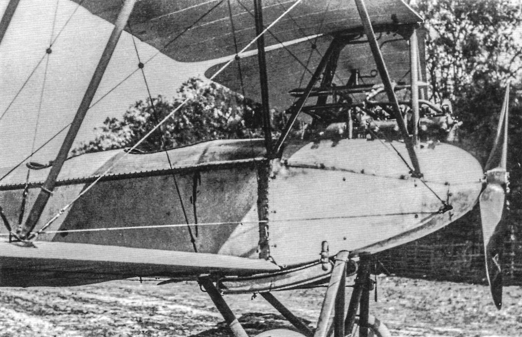
DFW flying boat in the DFW factory; the radiator on the nose is distinctive. This one-of-a-kind 1914 design had a Daimler engine in the hull driving a pusher propeller via a drive shaft. The empty weight was 820 kg. DFW owned the Lubeck-Travemunde firm which later produced a small number of floatplanes. (Peter M. Grosz Collection/SDTB)
DFW Pfeil Doppeldecker
The DFW Pfeil Doppeldecker (Arrow Biplane) followed the earlier DFW Mars biplanes with banana-shaped wing planform. The aircraft was smaller, lighter, and more streamlined than the Mars biplane for improved performance and agility.
Its compact design included a single bay of struts, greatly reducing drag compared to the three-and-a-half-bay Mars biplane. The engine was a 100 hp Daimler. The distinctive wing planform was not continued in future designs.
A DFW Arrow biplane provides a backdrop for this early photograph.
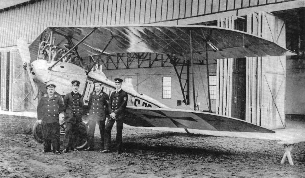
Herr Max Schuler (centre), who established a world's distance record with two passengers (seen in the photograph) by flying from Leipzig to Breslau - a distance of 205 miles - where he competed in the East German Race on his 150 h.p. D.F.W. scouting biplane. It was on the same machine, it will be remembered, that Herr Schuler won the German "Triangular" Race a short time ago.
Herr Max Schuler (centre), who established a world's distance record with two passengers (seen in the photograph) by flying from Leipzig to Breslau - a distance of 205 miles - where he competed in the East German Race on his 150 h.p. D.F.W. scouting biplane. It was on the same machine, it will be remembered, that Herr Schuler won the German "Triangular" Race a short time ago.
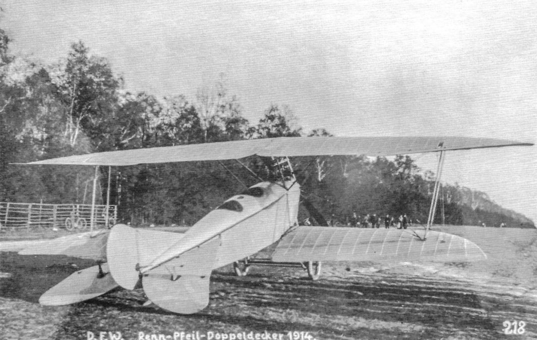
A DFW Renn Pfeil Doppeldecker (arrow biplane) seen from the rear. (Peter M. Grosz Collection/SDTB)
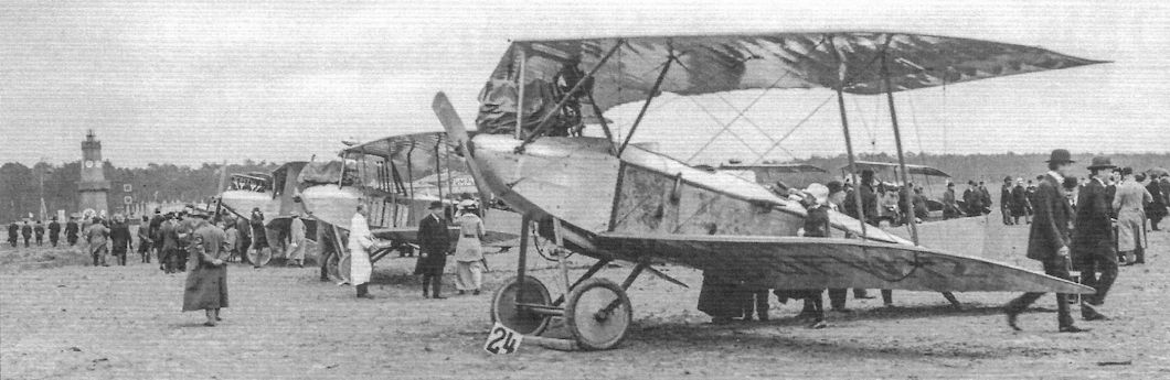
A DFW Pfeil Doppeldecker (arrow biplane) at a pre-war flight competition; the competition number is "24". (Peter M. Grosz Collection/SDTB)
A DFW Pfeil Doppeldecker with early national insignia on a white background under the wing. This is indicative of the photo being taken during the war. (Peter M. Grosz Collection/SDTB)
A DFW Pfeil Doppeldecker (arrow biplane) with pre-war registration under the lower wing.
A DFW Pfeil Doppeldecker (arrow biplane) ready for flight. (Peter M. Grosz Collection/SDTB)
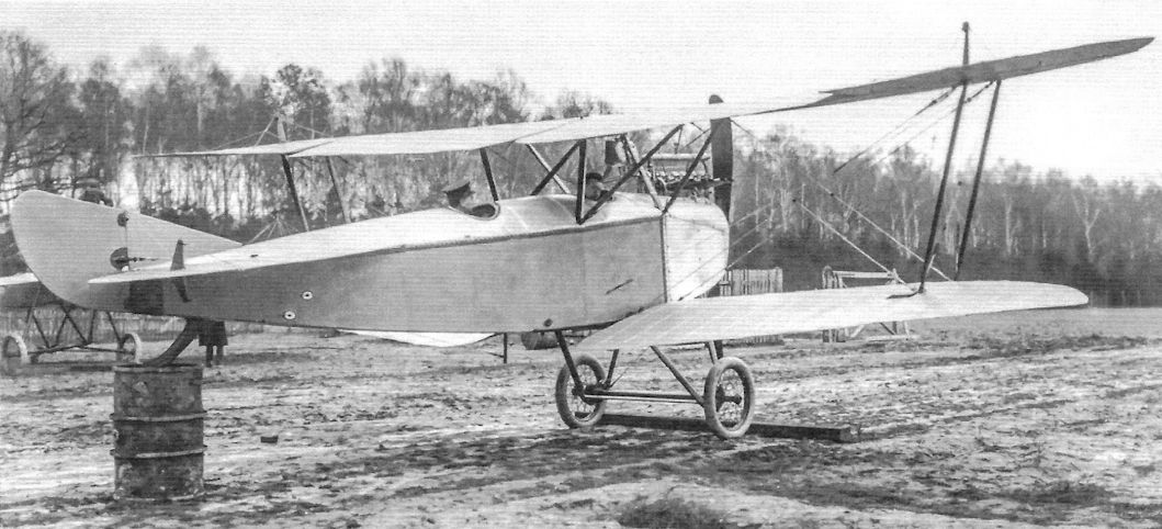
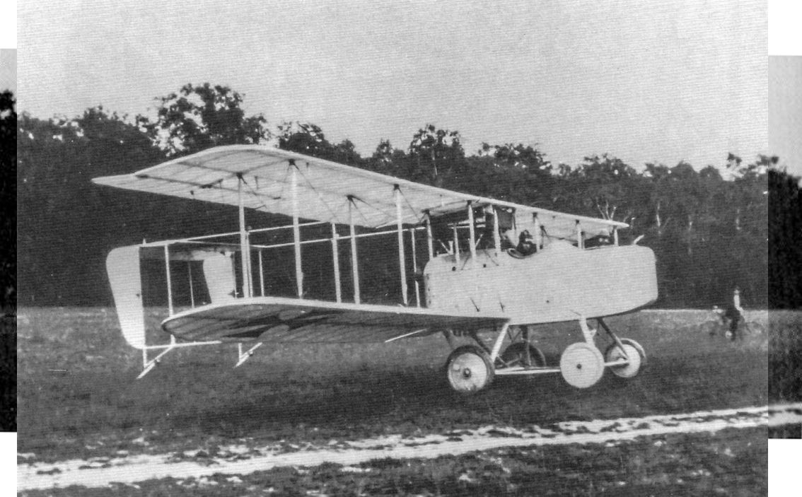
By 1914 the DFW company was producing elegant biplanes like this small two-seater. A production licence was agreed with Beardmore in the UK, but the war brought the scheme to an end.
By 1914 the DFW company was producing elegant biplanes like this small two-seater. A production licence was agreed with Beardmore in the UK, but the war brought the scheme to an end.
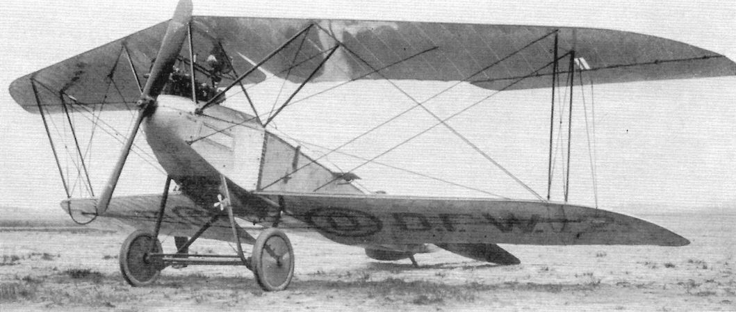
This DFW biplane appears to be the same type as that shown in the beginning of the section on page 9. The wings have a straight leading edge in contrast to the swept-back wings of the DFW Pfeil Doppeldecker although they retain the single-bay bracing. The engine appears to be a 100 hp Daimler.
A "D.F.W." scouting biplane, which is credited with a maximum speed of 106 to 110 miles per hour, and a minimum speed of 51 miles per hour. She will climb to an altitude of 3,500 ft. in about 6 mins.
A "D.F.W." scouting biplane, which is credited with a maximum speed of 106 to 110 miles per hour, and a minimum speed of 51 miles per hour. She will climb to an altitude of 3,500 ft. in about 6 mins.
Early DFW biplane at right with a Taube at left ready for another sortie early in the fighting. (Peter M. Grosz Collection/SDTB)
A DFW Pfeil Doppeldecker with crew aboard. (Peter M. Grosz Collection/SDTB)
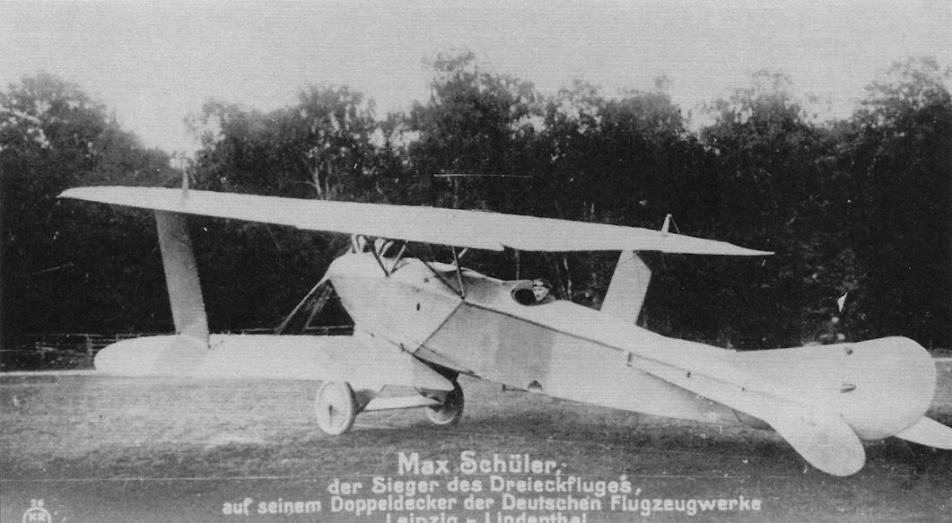
The DFW speed scout of 1914 was a single-seat, single-bay biplane with streamlined interplane and undercarriage struts designed for racing. The wings were shorter span than other DFWs and the tail resembled the DFW B.I. The engine was a 150 hp Benz Bz.III. This aircraft won the "Berliner Dreiecksflug 1914" competition. (Peter M. Bowers Collection/Museum of Flight)
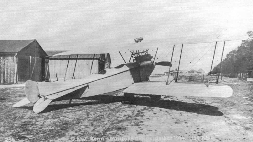
This DFW biplane appears to be a two-bay derivative of the biplane. The caption written on the photo indicates it was designed for the military and has a 150 hp engine. (Peter M. Grosz Collection/SDTB)
A DFW Arrow biplane with low-drag radiator under the wing. It is not known how many of these aircraft were built before the war.
DFW Tauben
The DFW Stahltaube (Iron Dove) was one of many derivatives of the Jeannin Taube (Dove) configuration. The DFW Military Taube was another that had its streamlined radiator mounted under the nose. Built in various versions in 1913-1914, these aircraft had a variety of six-cylinder engines like the 100 hp Mercedes. Empty weight was 820 kg.
The DFW Stahltaube (Iron Dove) was one of many derivatives of the Jeannin Taube (Dove) configuration. The DFW Military Taube was another that had its streamlined radiator mounted under the nose. Built in various versions in 1913-1914, these aircraft had a variety of six-cylinder engines like the 100 hp Mercedes. Empty weight was 820 kg.


DFW Stahltaube (Steel Dove) ready for another sortie; it had a 100 hp Mercedes and a simpler undercarriage than most Taube designs. The exhaust pipe was directed downward to exhaust under the fuselage. (Peter M. Bowers Collection/Museum of Flight)

The DFW Stahltaube (Steel Dove) had a 100 hp Mercedes or 95 hp Daimler and a simpler undercarriage than most Taube designs.The exhaust pipe was directed downward to exhaust under the fuselage. (Peter M. Grosz Collection/SDTB)

DFW military Taube with radiator mounted under the engine. This low-drag radiator was unique to DFW Taubes. (Peter M. Bowers Collection/Museum of Flight)

DFW military Taube A.5/14 (DFW works number 84) with streamlined radiator mounted under the engine. The photos were taken in the summer of 1914 right after the pristine aircraft left the factory. (Peter M. Grosz Collection/SDTB)

DFW military Taube A.5/14 (DFW works number 84) with streamlined radiator mounted under the engine. The photos were taken in the summer of 1914 right after the pristine aircraft left the factory. (Peter M. Grosz Collection/SDTB)

DFW military Taube with radiator mounted under the engine. (Peter M. Grosz Collection/SDTB)

This DFW Stahltaube (Steel Dove) was photographed at the DFW factory with DFW Chief Pilot Heinrich Oelerich. (Peter M. Grosz Collection/SDTB)

DFW military Taube with iron cross national insignia. (Peter M. Grosz Collection/SDTB)

This DFW military Taube was photographed at the DFW factory. (Peter M. Grosz Collection/SDTB)
Early DFW biplane at right with a Taube at left ready for another sortie early in the fighting. (Peter M. Grosz Collection/SDTB)

DFW trainers at the DFW flying school at Lubeck-Travemunde; a B.I at left with a lineup of Taubes. DFW also owned the Lubeck-Travemunde floatplane production factory; those floatplanes are covered in German Seaplanes of WWI.

DFW В-I на выставке трофейных вооружений в Париже, 1915 год
DFW B.I B.451/14 on display in Paris after being captured; a captured Taube is in the right background. The early national insignia on the rudder and both sides of all wings are well shown from this angle.
DFW B.I B.451/14 on display in Paris after being captured; a captured Taube is in the right background. The early national insignia on the rudder and both sides of all wings are well shown from this angle.

This refined DFW Taube with modernized tail design with elevators, rudder, and fixed fin was the next and final step in DFW Taube evolution, but the wings still used warping and not ailerons. The Taube configuration was obsolete. The fin and rudder design was similar to the Mars monoplanes and biplanes. (Peter M. Grosz Collection/SDTB)

In addition to the crashes, there were always taxi accidents, a particular hazard for these early aircraft without brakes. Here a DFW Mars biplane has experienced a close encounter of the worst kind with a Taube.

Crash of DFW military Taube A.183/13. Early national insignia are carried. This aircraft was assigned to Flieger Bataillon 1 in March 1913. (Peter M. Grosz Collection/SDTB)
DFW B-Types
Despite the fact that some DFW Mars biplanes served operationally early in the war, the only DFW B-type in the Frontbestand is the DFW B.I.
Many of the modest number of DFW B.I aircraft built were used for training in addition to frontline service early in the war. The DFW B.I was distinguished by its curved, 'banana-wing' planform.
An unknown number of DFW B.I aircraft were modified to give the observer a flexible machine gun, bridging the gap between B-types and C-types. The gun ring was position well above the fuselage, requiring the observer to stand to fire the gun. This
position gave the gunner a 360° field of fire above the horizontal. All these conversions look the same, indicating they were either modified at the factory or converted using a factory-supplied kit in the field.
Less well known is the DFW B.II, which featured a more common rectangular wing planform that was much less distinctive. The B.II served primarily, and perhaps solely, as a trainer.
Although the armed B.I conversion saw service, the follow-on DFW C.I was derived from the DFW B.II and the C.I armament mounting differed significantly from the armed B.I.
DFW B.I
The DFW B.I was a fairly typical unarmed two-seat reconnaissance airplane and trainer of its time with steel tube fuselage structure covered by fabric. The DFW factory designation was MD14 for Militar Doppeldecker (military biplane) 1914; DFW B.I was the military designation. The unusual curved 'banana wing' planform make the type distinctive, especially in flight where the wing planform was more visible.
A common engine was a 100 hp Mercedes D.I, although other early engines were also fitted in these early airframes, including 100-150 hp Argus and Benz engines. Side radiators were the 1914 state of the art in Germany and were installed on the B.I. On July 14, 1914, DFW chief pilot Heinrich Oelerich flew the MD14 to a height record of 8,150 m.
The DFW B.I was flown at the front in small numbers early in the war and was used to train pilots at the DFW flying school and the Lubeck-Travemunde flying school throughout the war.
The wingspan was 14 meters, length 8.40 meters, empty weight 650 kg, maximum flying weight 1,015 kg, and top speed 120 km/h.
DFW Armed B.I
According to the late historian Peter M. Grosz there was an order from November 1915 for conversion of DFW B-types to armed biplanes. The fact the gun mountings for these conversions all appear the same is consistent with the complex mounting being a factory design.

DFW B.I prototype.

DFW B.I TANNENBERG of the DFW flying school.

DFW B.I WARSCHAU of the DFW flying school.

DFW B.I aircraft in flight are easily identified by their distinctive wing planform.This one carries national insignia on both sides of all wings.

This DFW B.I carries national insignia on both sides of all wings. (Peter M. Bowers Collection/Museum of Flight)


The prototype DFW B.I in flight shows its distinctive banana-shaped wings. This photograph was used as the inset in the next photo. (Peter M. Grosz Collection/SDTB)

The prototype DFW B.I; the pilot sat in the rear cockpit. An inset shows it in flight.
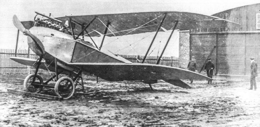
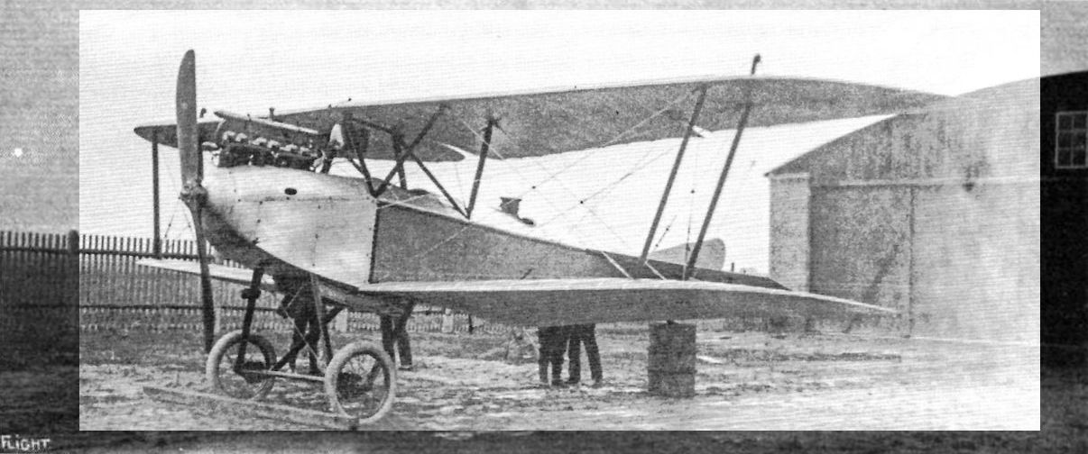
A "D.F.W." all-steel biplane, in which the only wood employed is that of the propeller. This machine, which was designed by Mr. Cecil Kny, the Technical Director, will be built in this country as soon as the new works at Richmond are completed. With a full load, including fuel for 5 1/2 hours and two passengers, the machine has climbed to a height of 3,500 ft. in 4 mins. The engine is a 100 h.p. Mercedes, and the speed is 78.4 miles per hour. Inset is a view of the machine in flight.
A "D.F.W." all-steel biplane, in which the only wood employed is that of the propeller. This machine, which was designed by Mr. Cecil Kny, the Technical Director, will be built in this country as soon as the new works at Richmond are completed. With a full load, including fuel for 5 1/2 hours and two passengers, the machine has climbed to a height of 3,500 ft. in 4 mins. The engine is a 100 h.p. Mercedes, and the speed is 78.4 miles per hour. Inset is a view of the machine in flight.

Closeup of the prototype DFW B.I. (Peter M. Grosz Collection/SDTB)

DFW chief pilot Heinrich Oelerich and a DFW MD14. Oelerich set a world altitude record in an MD14 on July 1914, and this photograph may have been in commemoration of that event.

DFW B.I DRESDEN was likely one of the trainers at the DFW flying school. (Peter M. Grosz Collection/SDTB)

Front view of a DFW B.I showing its three-bay wing cellule. (Peter M. Grosz Collection/SDTB)

DFW B.I WARSCHAU. The interesting thing about this aircraft is the wood vaneer used to cover the fuselage. This appears to be made from the Larch tree; this is very flexible before it is dry, but is like steel after it was dry. However, it was too expensive for general use. Very probably pilot Antoni Wroniecki, future member of Jasta 64w, is in the cockpit. He was shot down, wounded, and taken prisoner 14 April 1918 by 1/Lt Douglas Campbell from the 94th Aero Squadron, USAS.
Below: A closeup view of the side of DFW B.I WARSCHAU showing the wood grain and stenciling under the name.
Below: A closeup view of the side of DFW B.I WARSCHAU showing the wood grain and stenciling under the name.

The prototype DFW B.I displays its clean lines. (Peter M. Grosz Collection/SDTB)

DFW B.I at the DFW factory. It carries later national insignia on the rudder and both sides of all wings. (Peter M. Grosz Collection/SDTB)
Back view of D.F.W. B.I biplane, Reconnaissance and School type, nicknamed the "Banana" type owing to the wing shape.
Back view of D.F.W. B.I biplane, Reconnaissance and School type, nicknamed the "Banana" type owing to the wing shape.

DFW B.I carrying early national insignia on the rudder at the DFW factory. The tail is supported to bring the aircraft to level flight attitude while the crew familiarizes themselves with the aircraft. (Peter M. Grosz Collection/SDTB)

DFW B.I with a barely-visible crewman standing over the cockpits.

DFW B.I TANNENBERG was one of the trainers at the DFW flying school. (Peter M. Grosz Collection/SDTB)

DFW B.I at right at the DFW factory with national insignia on the rudder. The ground crew is positioning the aircraft. (Peter M. Grosz Collection/SDTB)
DFW В-I на выставке трофейных вооружений в Париже, 1915 год
DFW B.I B.451/14 on display in Paris after being captured; a captured Taube is in the right background. The early national insignia on the rudder and both sides of all wings are well shown from this angle.
DFW B.I B.451/14 on display in Paris after being captured; a captured Taube is in the right background. The early national insignia on the rudder and both sides of all wings are well shown from this angle.

DFW B.I B.451/14 on display at Les Invalides in Paris during September 1914.The early national insignia on the rudder and both sides of all wings are clearly shown. The insignia on the wings are painted well inboard.


DFW trainers at the DFW flying school at Lubeck-Travemunde; a B.I at left with a lineup of Taubes. DFW also owned the Lubeck-Travemunde floatplane production factory; those floatplanes are covered in German Seaplanes of WWI.

DFW B.I QUENTIN (left foreground) and DFW B.II ALICE (right foreground) share the DFW flight school lineup at Lindenthal with a DFW Stahltaube (far right) and other DFW B-types. From right to left in the background, the first three aircraft of DFW B.I, then a DFW B.II, another DFW B.I, and another DFW B.II. The seventh aircraft in the lineup at far left is likely a B.I although it is not clear enough for positive identification. A DFW B.I is in front of the hangar in the middle background and the tail visible to the left of that hangar belongs to a DFW B.II. The 'banana' wing planform of the DFW B.I contrasts clearly with the rectangular wing planform of the DFW B.II. The leading edge of the fin is straight in the B.I but curved in the B.II, the opposite of their wings.

DFW B.I and B.II trainers at Lindenthal as shown in issue Nr.3865 of the Illustrirte Zeitung. The aircraft types are indicated in hand printing under the photograph. (Peter M. Grosz Collection/SDTB)
Lineup of DFW B.I trainers at the DFW flying school at Lubeck-Travemunde. The aircraft at far right is Albatros C.I C.26/15 or perhaps C.26X/15. To the left of the Albatros C.I is DFW B.I GRAF SPEE, then B.I KAISER WILHELM, B.I LUTTICH, B.I SALEM ALEIKUM, B.I TANNENBERG, B.I name illegible, B.I QUENTIN, and several other DFW B.I trainers whose names cannot be read. (Peter M. Grosz Collection/SDTB)

To taxi the prototype Floh the pilot had to stand up to see over the high wing and fuselage. In addition to being highly streamlined, the DFW T 28 was very small, both factors contributing to its speed. DFW B.I trainers are in the background at DFW's Lubeck-Travemunde facility. (Peter M. Bowers Collection/Museum of Flight)

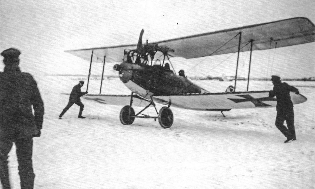
This DFW B.I carries early national insignia on the rudder and both sides of all wings. It is waiting in the snow while being prepared for its next mission. (Peter M. Grosz Collection/SDTB)

Ground crewmen steady the wings of a DFW B.I before take off. Early national insignia are on both sides of all wings. (Peter M. Grosz Collection/SDTB)

DFW B.I B.449/14 carries a white band on the fuselage and an early version of the national insignia on its rudder. (Peter M. Grosz Collection/SDTB)

This DFW B.I carries national insignia on both sides of all wings indicating it was used during the war. (Peter M. Grosz Collection/SDTB)

DFW B.I X38/14 carries early national insignia on the rudder. (Peter M. Grosz Collection/SDTB)

DFW B.I after capture by French forces. The serial is not visible but it is likely B.451/14.

DFW B.I B.451/14 after capture by French forces.This aircraft is marked with early national insignia on the rudder and both surfaces of all wings.

DFW B.I B.490/14 in the field carries early national insignia on the rudder and both sides of all wings.

Photo of armed DFW C.80/15.

Photo of armed DFW C.80/15. Although this appears to be a modified DFW B.I, the serial starts with 'C', not 'B', indicating the aircraft was designed to be armed at the DFW factory. Other than the gun and mounting, this aircraft was a standard DFW B.I with side radiators and 150 hp Benz Bz.III engine. Was C.80/15 the prototype conversion, or was the prototype conversion the aircraft without serial number shown on the previous pages? In any case, C.80/15 appears to be a transitional aircraft between the unarmed DFW B.I and the later DFW C.I.

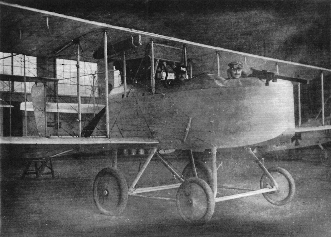
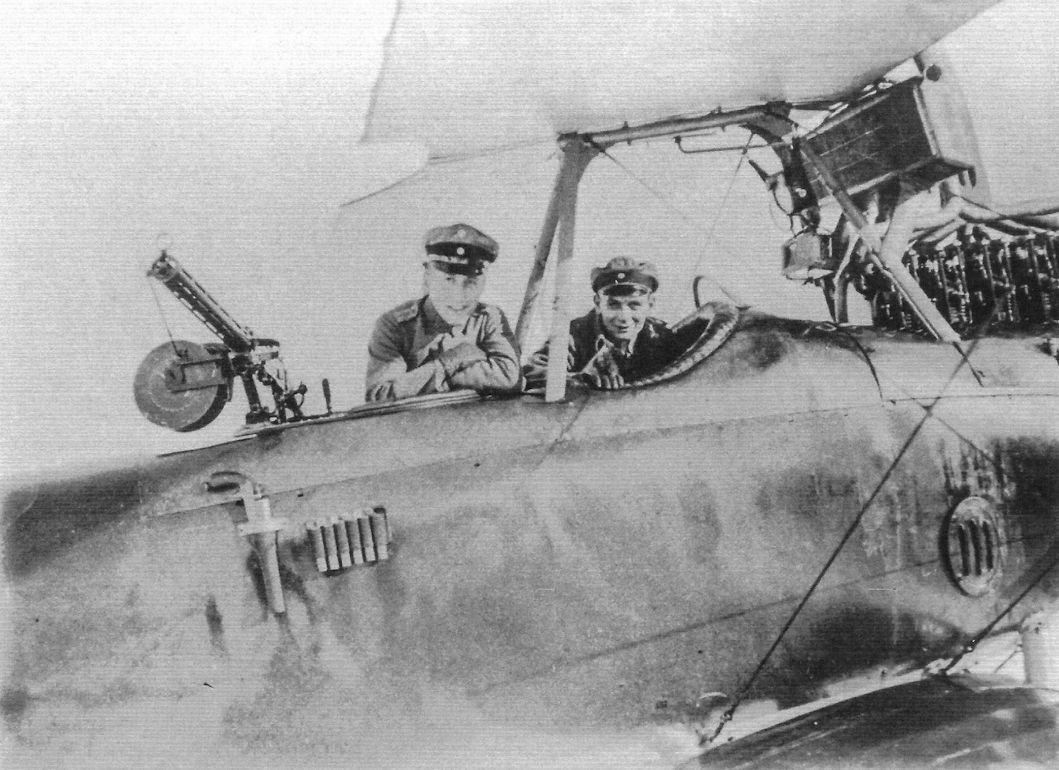
Armed DFW B.I. Although initially unarmed, some B-types were later modified to have a flexible gun for the observer. The elevated gun ring above the observer's cockpit on this DFW B.I gave a 360° field of fire above the upper wing. (Peter M. Bowers Collection/Museum of Flight)

This closeup shot of the aircraft at the top of the facing page shows that the 'gun' being used was a wooden mockup. (Peter M. Grosz Collection/SDTB)

Armed DFW B.I; the side radiators and 150 hp Benz Bz.III engine are well shown. This photo is likely of the same aircraft shown above. (Peter M. Grosz Collection/SDTB)

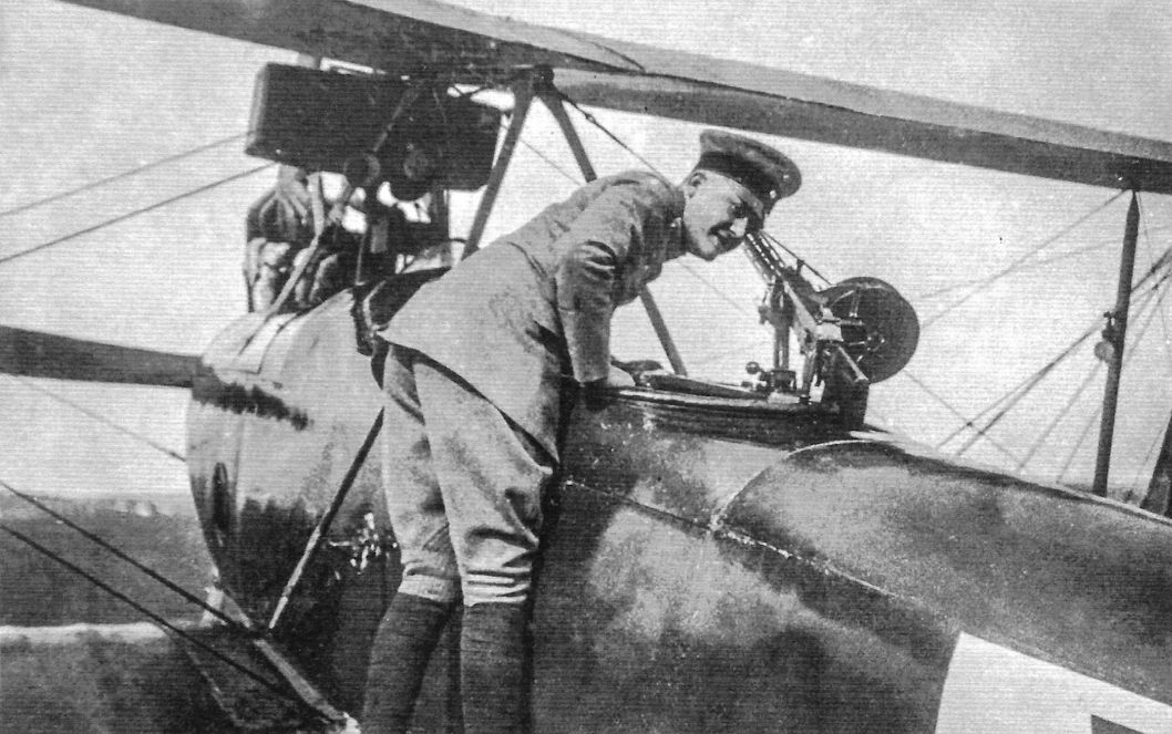
Armed DFW B type being inspected by officers. This photograph may be of C.80/15 on the facing page from a different angle. (Peter M. Grosz Collection/SDTB)

The observer occupied the front cockpit in DFW B-types, resulting in the complex gun mounting shown that enabled the observer to have a 360° field of fire above the aircraft. Were all these conversions performed at the factory, or were factory-designed and built kits supplied to the field for the conversions?
DFW B.I with Dr. Hochstetter at left.

DFW B.I of FFA 23 with Oblt. Willy Meyer on left and Hptm. Eberhard Bohnstedt at right.

DFW B.I aircraft B.620/14 and B.621/14 under construction in the DFW factory.

This DFW B.I carries a carbine for the crew. The carbine could provide limited self-defence for the aircraft and could also be used for self-defence after being forced down and possibly for hunting. (Peter M. Grosz Collection/SDTB)

This DFW B.I carries Imperial Russian Air Service cockades after being captured.

DFW B.I MACKENSEN on its nose. MACKENSEN was likely one of the trainers at the DFW flying school. (Peter M. Grosz Collection/SDTB)

DFW B.I WEDDINGEN after an incident at Leipzig-Lindenthal on 27 October 1915. WEDDINGEN was in training service at the DFW flying school there.

DFW B.I B.290/14 after a rough landing. An early version of the national insignia is on its rudder, indicating the photo was taken during the war.

Armed DFW B.I after a bad landing. Although this aircraft might be C.80/15, the two photos of C.80/15 show it with the entire rudder painted white. This aircraft has a white background for the national insignia on the rudder, which is otherwise in comparatively dark finish.

DFW B.I

DFW B.I

DFW B.I

DFW B.I

DFW B.I Armed Version

DFW B.I Armed Version

DFW B.I Armed Version

DFW B.I Armed Version
DFW B.II
The DFW B.II differed from the earlier B.I mainly in its wing design. The B.II wing abandoned the curved wing planform of the B.I for a rectangular planform with straight leading edges, and a two-bay design replaced the three-bay design of the B.I. The tail surfaces of the B.II were curved instead of straight like those of the B.I. The engine remained a 100 hp Mercedes D.I and side radiators were retained. The upper fuselage of the B.II was more contoured then that of the B.I. Photos show the B.II in service as a trainer. The Frontbestand does not show the B.II served at the front although that is not definitive; the DFW C.II and C.IV both served at the front and neither are listed in the Frontbestand.
DFW C-Types
<...>
In contrast to the excellent C.V, the other DFW C-types made no significant impact on the air war. The earlier production types, the C.I, C.II, and C.IV, were built and operated in very small numbers and made only a minor contribution to German aviation, being inferior to their competitors from Albatros and Rumpler. Their production orders and operational service was little-noted at the time, leaving only a sketchy record.
<...>
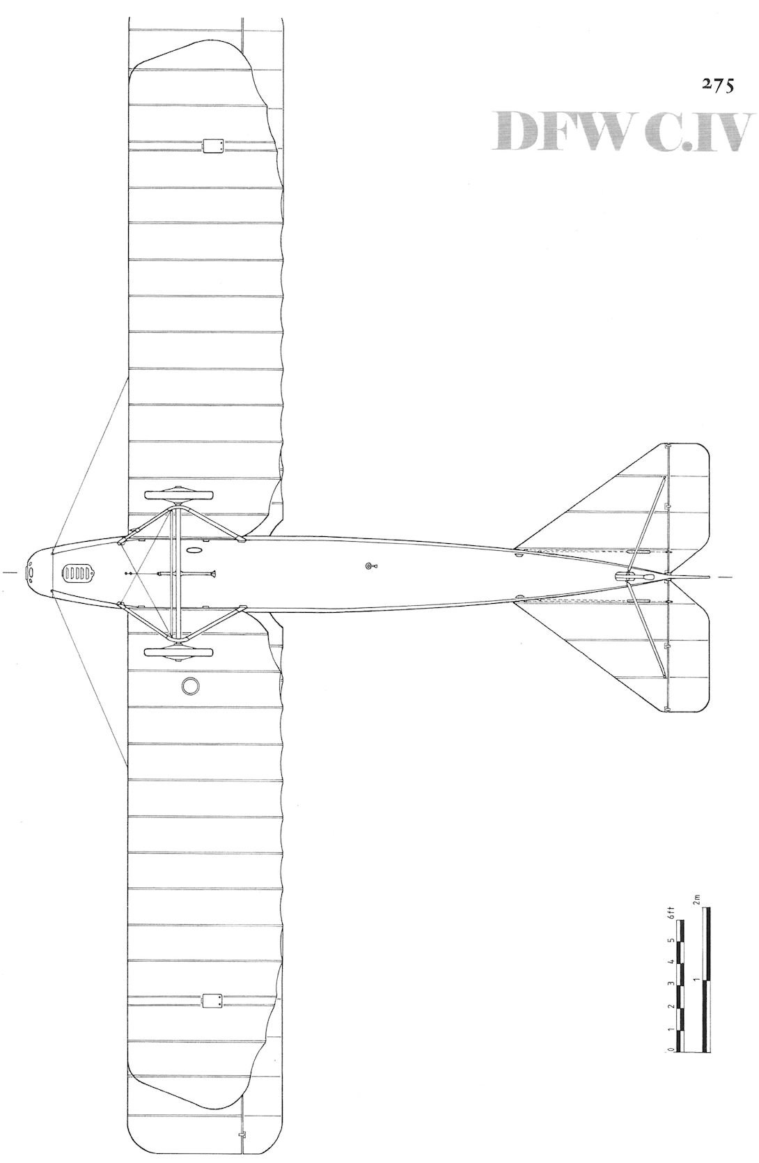
DFW C.I
DFW's first two-seater designed from the outset to be armed was the C.I. The C.I appears to be derived from the DFW B.II; the C.I had a more conventional, rectangular wing planform that abandoned the banana shape of the B.I. The superstructure for the observer's flexible gun used in the earlier armed B-types was eliminated to reduce drag; instead, the gunner, still in the front seat, had a gun ring with flexible machine gun. Curved steel tubes fitted on both sides of the aircraft between the forward cabane struts and the fuselage blocked the gunner from firing through the propeller arc.
The engine installed in the C.I was the reliable 150 hp Benz Bz.III that was more powerful than the 100 hp Mercedes used in most DFW B-types. Initially side radiators were used, but later C.I aircraft used a more modern leading edge radiator that had
lower drag than the side radiators. The leading edge radiator was also less prone to leaking and, in event of damage, offered more time before the cylinder heads were drained of water, enabling the engine to run a little longer after the water started leaking.
Two small batches of the DFW C.I are known, C.1500/15 - C.1528/15 (29 aircraft) and C.1975/15 - C.1985/15 (11 aircraft). Apparently fitting of leading edge radiators started in the first batch.
The late Peter M. Grosz indicated the DFW C.I was removed from the front due to weak wing spars. It is noted that three C.I aircraft completed the type test January 15, 1916, well after the C.I reached the front, and at a time when no C.I aircraft are shown in the Frontbeststand inventory. This may be the second type test for the DFW C.I confirming that the strengthened wing spars were satisfactory. The C.I returned to the front in small numbers a couple of months later, likely after the aircraft removed from the front were rebuilt with stronger wings.
The DFW C.I is known to have served with Bavarian FFA 1b in at least November/December 1915, and FFA 32 is also known to have used at least one DFW C.I. Documentation also shows the DFW C.I served with a number of schools, including FEA 6, FEA 8, FEA 10, FEA 11, FEA 1b, and Beobachterschule Thorn from at least July 1916 to February 1918.
DFW C.II
The DFW C.II was a simple development of the C.I. The observer, together with his flexible gun, was moved to the rear cockpit and the curved steel tubes fitted on both sides of the aircraft between the forward cabane struts and the fuselage on the C.I were eliminated as no longer necessary to block the gunner from firing through the propeller arc.
The engine installed in the C.II was the same reliable 150 hp Benz Bz.III that was installed in the C.I. The C.II also used the leading edge radiator that had been installed in later production C.I aircraft.
Known production of the DFW C.II was very small, a total of 12 aircraft with serials C.4200/15 - C.4211/15.
Based on photographs a small number of DFW C.II reconnaissance planes are thought to have been used operationally, but documentation is not available and they do not appear in the Frontbeststand inventory, so their service must have been brief.
Known DFW C.I, C.II, & C.IV Production Orders
Type Qty Serials Notes
C.I 29 C.1500-1528/15 Probably the full serial number range
C.I 11 C.1975-1985/15 Probably the full serial number range
C.II 12 C.4200-4211/15
These serial numbers are based on secondary data like photographs and strength reports, not primary sources like Idflieg orders. The highest serial numbers given for each type are the highest known.
DFW B & C-Type Specifications
DFW B.I DFW C.I DFW C.II DFW C.III
Engine 100 hp Mercedes D.I 150 hp Benz Bz.III 150 hp Benz Bz.III 160 hp Mercedes D.III 150 hp Benz Bz.III
Span, Upper 14.0 m 14.0 m - -
Span, Lower - - - -
Chord, Upper - - - -
Chord, Lower - - - -
Gap - - - -
Wing Area - 40 tn2 - -
Length 8.4 m 8.4 m - -
Height 3.18 m 3.18 m - -
Empty Weight 650 kg 800 kg 725 kg -
Loaded Weight 1,015 kg 1,140 kg 1,235 kg -
Maximum Speed 120 km/h 130 km/h 140 km/h -
Climb to 1,000m - - - -
Climb to 2,000m - - - -
Climb to 3,000m - - - -
Climb to 4,000m - - - -
The DFW B.II differed from the earlier B.I mainly in its wing design. The B.II wing abandoned the curved wing planform of the B.I for a rectangular planform with straight leading edges, and a two-bay design replaced the three-bay design of the B.I. The tail surfaces of the B.II were curved instead of straight like those of the B.I. The engine remained a 100 hp Mercedes D.I and side radiators were retained. The upper fuselage of the B.II was more contoured then that of the B.I. Photos show the B.II in service as a trainer. The Frontbestand does not show the B.II served at the front although that is not definitive; the DFW C.II and C.IV both served at the front and neither are listed in the Frontbestand.
DFW C-Types
<...>
In contrast to the excellent C.V, the other DFW C-types made no significant impact on the air war. The earlier production types, the C.I, C.II, and C.IV, were built and operated in very small numbers and made only a minor contribution to German aviation, being inferior to their competitors from Albatros and Rumpler. Their production orders and operational service was little-noted at the time, leaving only a sketchy record.
<...>
DFW C.I
DFW's first two-seater designed from the outset to be armed was the C.I. The C.I appears to be derived from the DFW B.II; the C.I had a more conventional, rectangular wing planform that abandoned the banana shape of the B.I. The superstructure for the observer's flexible gun used in the earlier armed B-types was eliminated to reduce drag; instead, the gunner, still in the front seat, had a gun ring with flexible machine gun. Curved steel tubes fitted on both sides of the aircraft between the forward cabane struts and the fuselage blocked the gunner from firing through the propeller arc.
The engine installed in the C.I was the reliable 150 hp Benz Bz.III that was more powerful than the 100 hp Mercedes used in most DFW B-types. Initially side radiators were used, but later C.I aircraft used a more modern leading edge radiator that had
lower drag than the side radiators. The leading edge radiator was also less prone to leaking and, in event of damage, offered more time before the cylinder heads were drained of water, enabling the engine to run a little longer after the water started leaking.
Two small batches of the DFW C.I are known, C.1500/15 - C.1528/15 (29 aircraft) and C.1975/15 - C.1985/15 (11 aircraft). Apparently fitting of leading edge radiators started in the first batch.
The late Peter M. Grosz indicated the DFW C.I was removed from the front due to weak wing spars. It is noted that three C.I aircraft completed the type test January 15, 1916, well after the C.I reached the front, and at a time when no C.I aircraft are shown in the Frontbeststand inventory. This may be the second type test for the DFW C.I confirming that the strengthened wing spars were satisfactory. The C.I returned to the front in small numbers a couple of months later, likely after the aircraft removed from the front were rebuilt with stronger wings.
The DFW C.I is known to have served with Bavarian FFA 1b in at least November/December 1915, and FFA 32 is also known to have used at least one DFW C.I. Documentation also shows the DFW C.I served with a number of schools, including FEA 6, FEA 8, FEA 10, FEA 11, FEA 1b, and Beobachterschule Thorn from at least July 1916 to February 1918.
DFW C.II
The DFW C.II was a simple development of the C.I. The observer, together with his flexible gun, was moved to the rear cockpit and the curved steel tubes fitted on both sides of the aircraft between the forward cabane struts and the fuselage on the C.I were eliminated as no longer necessary to block the gunner from firing through the propeller arc.
The engine installed in the C.II was the same reliable 150 hp Benz Bz.III that was installed in the C.I. The C.II also used the leading edge radiator that had been installed in later production C.I aircraft.
Known production of the DFW C.II was very small, a total of 12 aircraft with serials C.4200/15 - C.4211/15.
Based on photographs a small number of DFW C.II reconnaissance planes are thought to have been used operationally, but documentation is not available and they do not appear in the Frontbeststand inventory, so their service must have been brief.
Known DFW C.I, C.II, & C.IV Production Orders
Type Qty Serials Notes
C.I 29 C.1500-1528/15 Probably the full serial number range
C.I 11 C.1975-1985/15 Probably the full serial number range
C.II 12 C.4200-4211/15
These serial numbers are based on secondary data like photographs and strength reports, not primary sources like Idflieg orders. The highest serial numbers given for each type are the highest known.
DFW B & C-Type Specifications
DFW B.I DFW C.I DFW C.II DFW C.III
Engine 100 hp Mercedes D.I 150 hp Benz Bz.III 150 hp Benz Bz.III 160 hp Mercedes D.III 150 hp Benz Bz.III
Span, Upper 14.0 m 14.0 m - -
Span, Lower - - - -
Chord, Upper - - - -
Chord, Lower - - - -
Gap - - - -
Wing Area - 40 tn2 - -
Length 8.4 m 8.4 m - -
Height 3.18 m 3.18 m - -
Empty Weight 650 kg 800 kg 725 kg -
Loaded Weight 1,015 kg 1,140 kg 1,235 kg -
Maximum Speed 120 km/h 130 km/h 140 km/h -
Climb to 1,000m - - - -
Climb to 2,000m - - - -
Climb to 3,000m - - - -
Climb to 4,000m - - - -

DFW C.I C.1501/15 of Feld-Flieger-Abteilung 1b, November-December 1915.

DFW C.I C1512/15 (or C.1513/15; the final digit is not fully legible in the reference photo). This C.I has the leading edge radiator that was standard on the C.II. Unit unknown.

DFW C.II C.4207/15, unit unknown.


DFW B.II, perhaps B.641/14. (Peter M. Grosz Collection/SDTB)

DFW B.II B.655/14. (Peter M. Grosz Collection/SDTB)

DFW B.II in pristine condition but with no serial number. (Peter M. Grosz Collection/SDTB)

This DFW B.II trainer was still flying in 1918; the old-style insignia remain on the wings but the new-style insignia have been applied to the fuselage. (Peter M. Grosz Collection/SDTB)

A DFW B.II trainer with student in front and instructor in the back cockpit. The dual controls are connected by rods that protrude outside the fuselage.

A DFW B.II trainer forms the backdrop for this portrait of aviators taken at DFW's Leipzig-Lindenthal flying school on 3 September 1915. The flight student in the center is Kurt Wusthoff; Wusthoff became a fighter ace with 27 victories who was awarded the Pour le Merits and survived the war. (Peter M. Grosz Collection/SDTB)
DFW B.I QUENTIN (left foreground) and DFW B.II ALICE (right foreground) share the DFW flight school lineup at Lindenthal with a DFW Stahltaube (far right) and other DFW B-types. From right to left in the background, the first three aircraft of DFW B.I, then a DFW B.II, another DFW B.I, and another DFW B.II. The seventh aircraft in the lineup at far left is likely a B.I although it is not clear enough for positive identification. A DFW B.I is in front of the hangar in the middle background and the tail visible to the left of that hangar belongs to a DFW B.II. The 'banana' wing planform of the DFW B.I contrasts clearly with the rectangular wing planform of the DFW B.II. The leading edge of the fin is straight in the B.I but curved in the B.II, the opposite of their wings.
DFW B.I and B.II trainers at Lindenthal as shown in issue Nr.3865 of the Illustrirte Zeitung. The aircraft types are indicated in hand printing under the photograph. (Peter M. Grosz Collection/SDTB)

This DFW C.I carries national markings but no serial number. It has the early side radiators and a machine gun, or mockup gun, is also carried. The standard curved steel tubs to prevent the observer from firing through the propeller arc are not fitted. Photographed at the DFW factory, it may be the DFW C.I prototype. (Peter M. Grosz Collection/SDTB)

The DFW C.I with the observer's flexible machine gun mounted on the gun ring in the front cockpit and the curved steel tubes from the forward cabane struts to the fuselage fitted to prevent the observer from firing through the propeller arc. Side radiators are fitted. (Peter M. Grosz Collection/SDTB)

An early DFW C.I is the background for this portrait.

Ground crew load a 10 kg Carbonit bomb in DFW C.I C.1501/15 of Bavarian FFA 1b. This was the largest bomb that observers could reasonably drop by hand. This high explosive bomb was made by the Sptrngstoff AG Carbonit - Schlebusch company. The aircraft has such an overall light color that no white backgrounds are needed for the national insignia.

This unidentified DFW C.I carries identification streamers and differently-shaped steel guardrails to prevent the observer from firing through the propeller arc. (Peter M. Grosz Collection/SDTB)

This unidentified DFW C.I carries identification streamers and differently-shaped steel guardrails to prevent the observer from firing through the propeller arc. The presence of a pilot without observer may indicate it is in training service or that the pilot is preparing for a training flight. (Peter M. Grosz Collection/SDTB)

The DFW C.I was developed from the earlier DFW B-types and retained the pilot in the aft cockpit. The observer occupied the front cockpit and the curved steel tubes from the forward cabane struts to the fuselage were fitted to prevent the observer from firing through the propeller arc. The C.I was powered by a 150 hp Benz Bz.III. Uffz. F. Decker was photographed in front of this DFW C.I used as a trainer at Flieger Ersatz Abteilung 6. (Peter M. Grosz Collection/SDTB)

Ground crew check the rigging on DFW C.I C.15XX/15. (Peter M. Grosz Collection/SDTB)

Pristine DFW C.I C.1508/15 shows its overall light coloring. (Peter M. Grosz Collection/SDTB)

DFW C.I C.1511/15 heads this DFW C.I lineup.
DFW C.I C.1505/15 is in the left center background in front of the Fokker Eindecker in this photo of Feld-Flieger Abteilung 61. LVG B.I and Albatros B.II aircraft form part of this motley collection. (Bruno Schmaling)

DFW C.I C.1512/15 or C.1513/15; the curved steel tube from the forward port cabane strut to the fuselage fitted to prevent the observer from firing through the propeller arc is clearly visible. This aircraft has a leading edge radiator instead of the side radiators of earlier C.I aircraft.

This DFW C.I carries national markings but no visible serial number. The cooling system has been improved with a leading edge radiator instead of the early side radiators. (Peter M. Grosz Collection/SDTB)

Another view of DFW C.I C.1527/15 in flight. (Peter M. Grosz Collection/SDTB)

DFW C.I C.1527/15 in flight.

DFW C.I C.1507/15 of Bavarian FFA 1b in flight.

The DFW C.II used the engine and airframe of the C.I but the pilot was moved to the front cockpit. The observer occupied the rear cockpit and had a flexible machine gun. The curved steel tubes from the forward cabane strut to the fuselage fitted to the C.I to prevent the observer from firing through the propeller arc was no longer needed on the C.II. A leading edge radiator was used in place of the side radiators used on the C.I aircraft. (Peter M. Grosz Collection/SDTB)

The DFW C.II used the engine and airframe of the C.I but the pilot was moved to the front cockpit and the observer occupied the rear cockpit and had a flexible machine gun. (Peter M. Grosz Collection/SDTB)

DFW C.II C.4207/15 in the factory. The observer in the rear cockpit is the key identifying feature of the DFW C.II compared to the C.I. Also, the C.II did not use the side radiators used on early C.I aircraft.

Portrait of a proud pilot in his DFW C.II. (Peter M. Grosz Collection/SDTB)

Observer Erhler proudly stands in front of a DFW C.II for his portrait. The lack of the C.I's curved steel tubes from the forward cabane strut to the fuselage fitted to prevent the observer from firing through the propeller arc identifies this aircraft as a DFW C.II.

A DFW C.II in flight. The leading edge radiator and lack of the curved steel tubes attached to the front cabane struts differentiate the C.II from the C.I that used the same basic airframe.

DFW C.II C.4204/15 in flight. (Peter M. Grosz Collection/SDTB)

DFW C.II C.2733/15 in flight; interestingly, this serial does not appear in the lists. (Peter M. Grosz Collection/SDTB)

DFW C.II C.4207/15 in flight. (Peter M. Grosz Collection/SDTB)

DFW C.II C.4203/15 in flight. (Bruno Schmaling)

DFW C.II C.420X/15 after a bad landing. The overall finish is very light. (Peter M. Grosz Collection/SDTB)

DFW C.II C.4200/15 after a crash. No white insignia backgrounds are needed over the light finish. (Peter M. Grosz Collection/SDTB)

This single-bay biplane with I-strut bracing was clearly a predecessor of the DFW C.V, but its exact role is not known. It may have been the C.III as indicated by one document, but the C.III is generally thought to be the DFW pusher.

DFW C.I

DFW C.I

DFW C.I

DFW C.I, DFW C.II

DFW C.II

DFW C.II

DFW C.II
DFW C.III
DFW built a prototype pusher two-seater shown in the photograph. This aircraft, thought to be designated the DFW C.III, may have remained a single prototype but was photographed with two significantly different radiator arrangements so more than one prototype may have been built. The engine installed in the C.III was the same 150 hp Benz Bz.III that was used in the DFW C.I and C.II.
Pushers were not popular in Germany and few pusher designs were built. Although pushers had the advantage of unobstructed forward view and field of fire for the observer, the extensive structure supporting the tail created excessive drag, limiting speed and climb. Worse, a gunner in the front cockpit had a limited field of fire to the rear, and none to the rear and below, making pusher aircraft very vulnerable to fighter attack.
The C.III appears to have been built using the same engine as the tractor C.I and C.II to compare the two configurations. The limitations of the pusher arrangement clearly made the success of such an experiment unlikely, and no production of the pusher was undertaken.
DFW B & C-Type Specifications
DFW C.III
Engine 150 hp Benz Bz.III
This two-seat DFW pusher is thought to be the C.III but this is not confirmed. Like the C.I and C.II, the engine was a 150 hp Benz Bz.III. The pusher configuration was not popular in Germany due to its high drag, which limited performance and the observer's field of fire to the rear, increasing the difficulty in defending the aircraft from rear attack.
This view of the DFW C.III shows the 3-bay wing cellule to advantage. This aircraft has side radiators and was likely the first configuration of the C.III. (Peter M. Grosz Collection/SDTB)
Two crewmen pose in the DFW C.III with block radiator under the leading edge of the upper wing, a more advanced configuration than side radiators. It is not known if this was a modification of the prototype or a second prototype. The observer/gunner has a wooden mockup of a machine gun. (Peter M. Grosz Collection/SDTB)
DFW Floh (Flea)
For some reason the T 28 Floh was designed and built at DFW's facility at Lubeck-Travemunde where the DFW flight school was located. Diplom-Ingenieur Hermann Dorner, DFW's new lead engineer, proposed the aircraft in 1915 and Ingenieur Theo Rockenfeller led the detail design and construction.
The motivation for the T 28 was to produce a much faster fighter than the Fokker Eindeckers then in combat, and great attention to streamlining to minimize drag coupled with light weight was seen as the solution. An airfoil radiator was fitted in the upper left wing and gravity fuel tanks in both upper wings. The airfoil was comparatively thick and the leading edge was covered in thin plywood as was the fuselage. Control cables were internal to the structure. The pilot had an excellent field of view upward but not downward and forward, which made landing difficult.
When the Floh was demonstrated to the Army, the officials decided it was too fast (!) and especially that the landing speed was too high.
DFW Fighter Specifications
DFW Floh DFW D.l DFW Dr.I DFW D.II
Engine 100 hp Mercedes D.l 160 hp Mercedes D.III 160 hp Mercedes D.III 170 hp Mercedes D.IIIa
Span, Upper 6.5 m - - 9.08 m
Wing Area - - - 23.00 m2
Length 4.5 m - - 5.5 m
Empty Weight 352 kg - - 639 kg
Loaded Weight 596 kg - - 819 kg
Maximum Speed 180 km/h - - 177 km/h
Climb to 4,000m - - - 10 minutes
Armament One gun Two guns Two guns Two guns

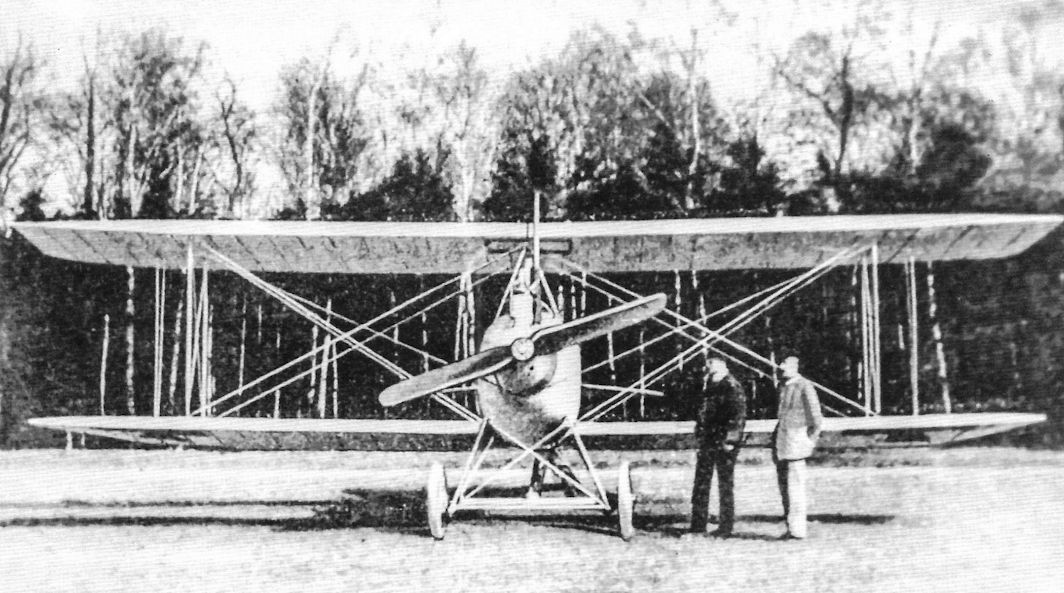
The designer of the DFW T 28 Floh photographed with his creation. This photo emphasizes the small size of the aircraft. Only one synchronized machine gun was fitted. Despite extraordinary appearance, the T 28 Floh achieved a respectable performance. (Peter M. Bowers Collection/Museum of Flight)

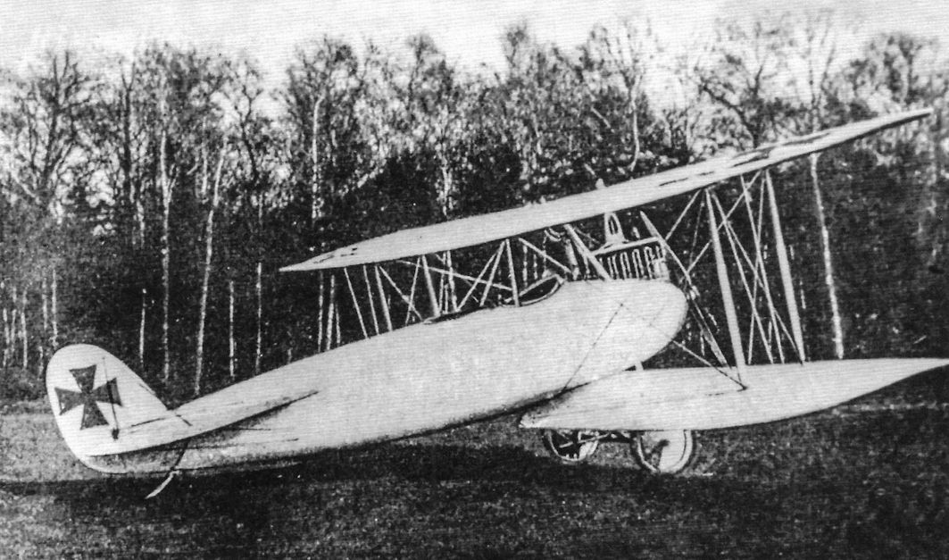
The DFW T 28 Floh had a very unusual configuration. The pilot had an excellent field of view upward but the wings obstructed the view forward and downward that made landing problematic. (Peter M. Grosz Collection/SDTB)
To taxi the prototype Floh the pilot had to stand up to see over the high wing and fuselage. In addition to being highly streamlined, the DFW T 28 was very small, both factors contributing to its speed. DFW B.I trainers are in the background at DFW's Lubeck-Travemunde facility. (Peter M. Bowers Collection/Museum of Flight)

The bizarre DFW T 28 Floh was fast for its 100 hp Mercedes D.I due to its excellent streamlining, achieving 180 km/h on its maiden flight, but Idflieg had little interest in the type. It featured conventional wood, wire, and fabric wings with plywood-wrapped fuselage over a wooden frame like the DFW C.IV that was designed at nearly the same time. An exhaust header was omitted to minimize weight and drag.

The original tail design of the DFW T 28 Floh without aerodynamic balances on the elevators. There was no fixed fin and no bracing for the tail surfaces. (Peter M. Bowers Collection/Museum of Flight)

The initial tail design of the DFW T 28 Floh is shown in this rear view. (Peter M. Grosz Collection/SDTB)

The final tail design of the DFW T 28 Floh with aerodynamic horn balances on the elevators is shown here. (Peter M. Bowers Collection/ Museum of Flight)

DFW T28 Floh (Flea)

DFW T28 Floh (Flea)
Known DFW C.I, C.II, & C.IV Production Orders
Type Qty Serials Notes
C.IV 6 C.2374-2379/16 Probably not the full serial number range
These serial numbers are based on secondary data like photographs and strength reports, not primary sources like Idflieg orders. The highest serial numbers given for each type are the highest known.
DFW C-Type Specifications
DFW C.IV DFW C.V DFW C.VI DFW C.VII
Engine 150 hp Benz Bz.III 200 hp Benz Bz.IV 220 hp Benz Bz.IVa 220 hp Benz Bz.IVa
Span, Upper 13.30 m 13.27 m 13.60 m 13.60 m
Span, Lower - 12.80 m - -
Chord, Upper - 1.75 m - -
Chord, Lower - 1.75 m - -
Gap - 1.80 m - -
Wing Area 42.2 m2 41.52 m2 - 38.0 m2
Length 7.90 m 7.88 m 7.50 m 7.0 m
Height 3.3 m 3.26 m - 2.8 m
Empty Weight 720 kg 1,027 kg - 800 kg
Loaded Weight 1,230 kg 1,477 kg - 1,230 kg
Maximum Speed 135 km/h 155 km/h - 160 km/h
Climb to 1,000m - 4.0 minutes - 3.0 minutes
Climb to 2,000m - 7.0 minutes - -
Climb to 3,000m - 15.0 minutes - -
Climb to 4,000m - 25.0 minutes - -
Climb to 5,000m - 40.0 minutes - -
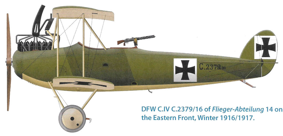
DFW C.IV C.2379/16 of Flieger-Abteilung 14 on the Eastern Front, Winter 1916/1917.
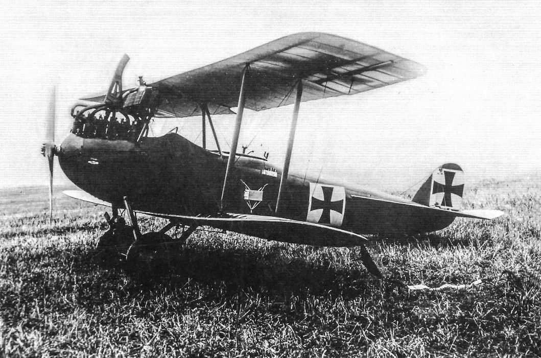
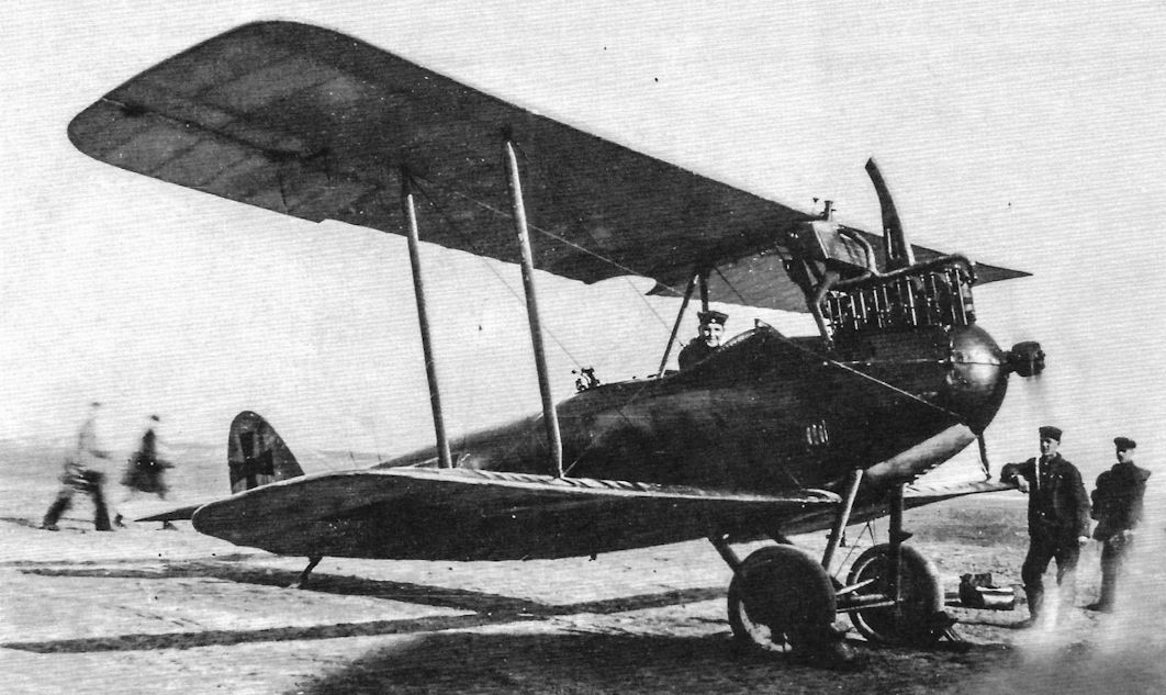
The DFW T 25 was the factory designation for the production DFW C.IV; this aircraft appears to be a prototype for the C.IV. Although the streamlined plywood fuselage presented a more modern appearance than the DFW C.I and C.II, the engine remained a 150 hp Benz Bz.III as used in those earlier designs. (Peter M. Grosz Collection/SDTB)
Ground crew steady a DFW C.IV of Flieger Abteilung 14 before it starts accelerating for take-off. (Peter M. Grosz Collection/SDTB)
With its rounded plywood fuselage and single-bay bracing the DFW C.IV was a complete departure from earlier DFW C-types. However, the engine remained a 150 hp Benz Bz.III. A leading edge radiator was fitted. An identification streamer is attached to the lower left wing tip and a barograph is suspended between the wings. (Peter M. Grosz Collection/SDTB)
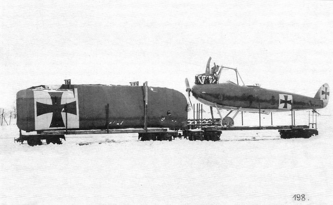
The full photograph shows a DFW C.IV on its way to the front during the winter on a pair of railroad cars, the fuselage on one car and the wings on another. The circle on the wing root is likely the magnetic compass housing.

A DFW C.IV on its way to the front on a train. This view shows the dark green upper camouflage and light undersurface camouflage applied to the streamlined fuselage to advantage. The national insignia require white backgrounds over these colors. No individual or unit markings are applied. The weight for the wireless antenna hanging below the fuselage is clearly visible. The serial is difficult to read but appears to be C.2375/16.
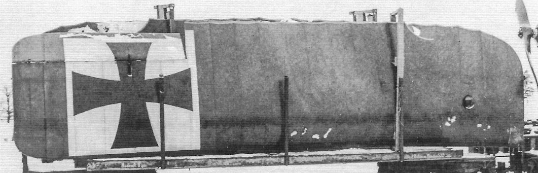
The wings of the DFW C.IV shown opposite on its way to the front on a train; the propeller is at far right.
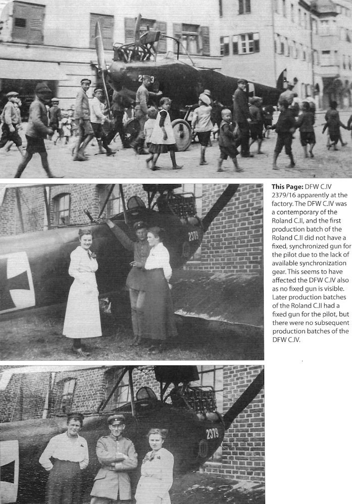
DFW C.IV 2379/16 apparently at the factory. The DFW C.IV was a contemporary of the Roland C.II, and the first production batch of the Roland C.II did not have a fixed, synchronized gun for the pilot due to the lack of available synchronization gear. This seems to have affected the DFW C.IV also as no fixed gun is visible. Later production batches of the Roland C.II had a fixed gun for the pilot, but there were no subsequent production batches of the DFW C.IV.
A ground crewman warms up a DFW C.IV. The rounded plywood fuselage was carefully streamlined and well-finished to minimize drag. (Peter M. Grosz Collection/SDTB)
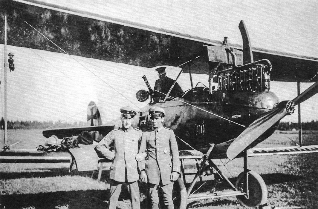
DFW C.IV and ground crew assigned to FliegerAbteilung 15 on the Eastern Front. (Peter M. Grosz Collection/SDTB)
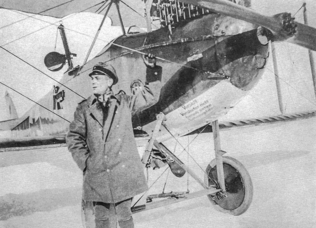
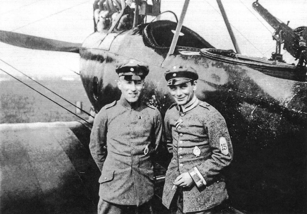
Vzfw. Karl Reum with a DFW C.IV of FliegerAbteilung 15, Eastern Front. The stenciling on the lower cowling reads: Vorsicht - Vorstecker nicht - herausziehen - Lebensgefahr!, meaning: Attention - Safety pin do not - pull out - Risk of death! (Peter M. Grosz Collection/SDTB)
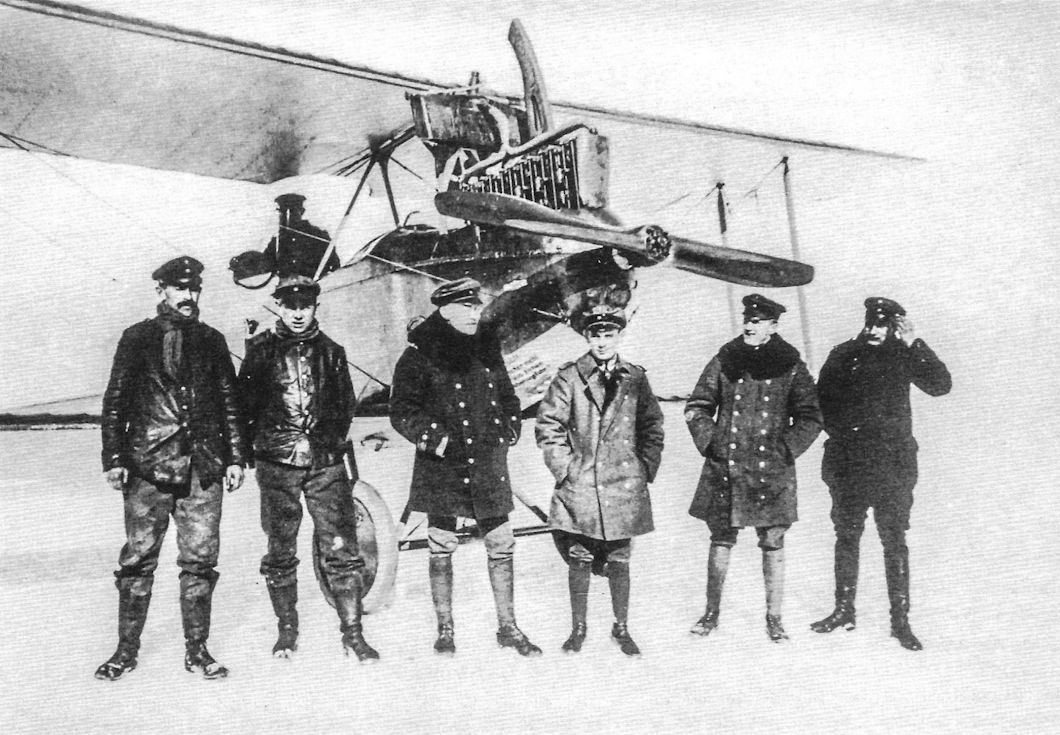
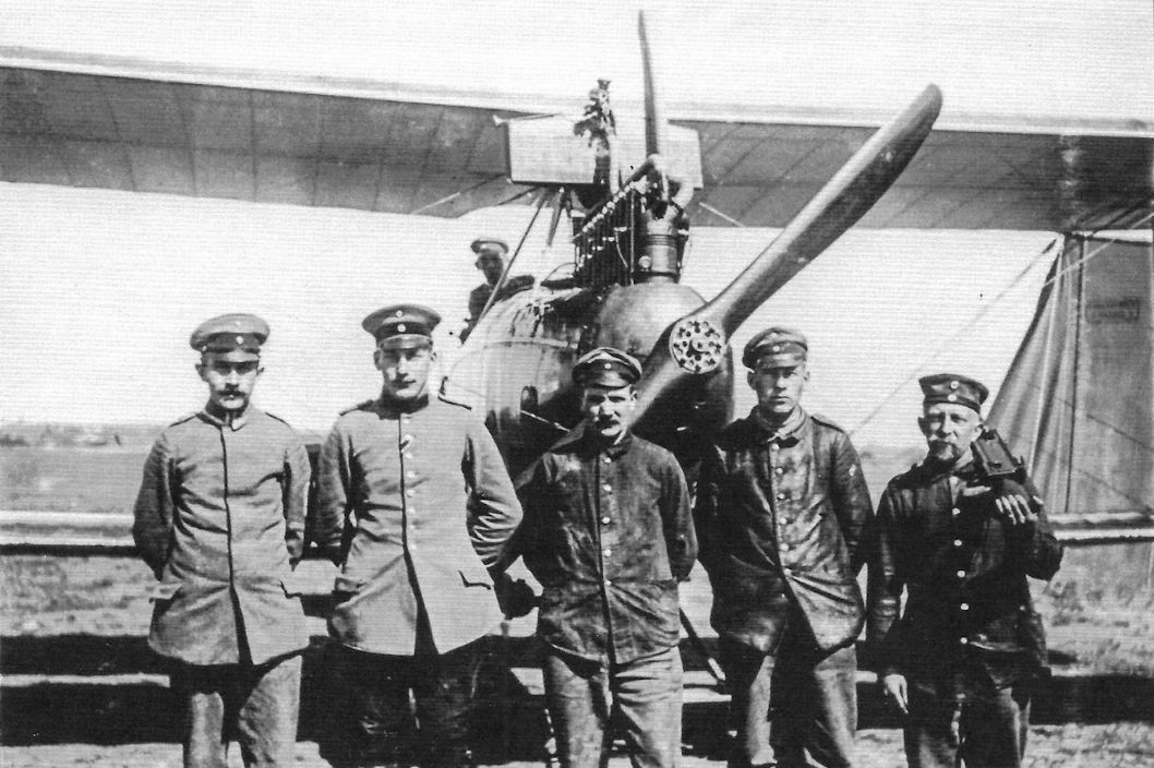
Men of Flieger Abteilung 14 on the Eastern Front pose for their portrait with a DFW C.IV in winter. From left the men are Uffz. Sonntag, Gefr. Gerber, Uffz. Reum, Gefr. Schickel, Werkm. Grube, unknown. (Peter M. Grosz Collection/SDTB)
Crewman and a DFW C.IV of FliegerAbteilung 15, Eastern Front. (Peter M. Grosz Collection/SDTB)
The crew of a DFW C.IV of FliegerAbteilung 14 (or 15?) poses for their portrait. (Peter M. Grosz Collection/SDTB)
Crew of Flieger Abteilung 15 on the Eastern Front pose for their portrait with a DFW C.IV. The man on the right has a Flieger Abteilung 15 patch on the sleeve of his tunic. (Peter M. Grosz Collection/SDTB)
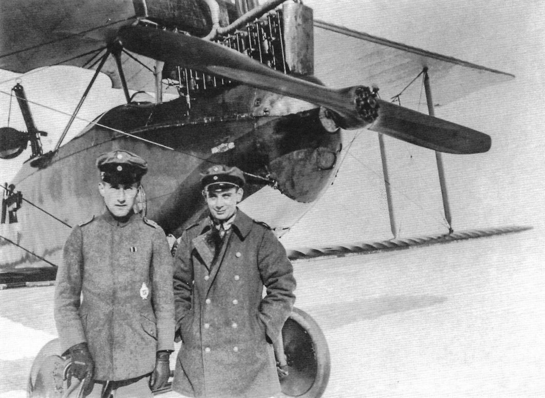
The crew of a DFW C.IV poses for their portrait; Lt. Hermann is the observer and Uffz. Reims is the pilot. The rounded plywood fuselage was carefully streamlined and well-finished to minimize drag. The C.IV carried a flexible gun for the observer but no fixed gun for the pilot; the first production batch of the Roland C.II was similarly armed. Later production batches of the Roland C.II provided a fixed, synchronized gun for the pilot; however, there was no second production batch for the DFW C.IV, whose performance did not justify greater production. A flare gun and belt of signal flares are attached to the fuselage outside the observer's cockpit. (Peter M. Grosz Collection/SDTB)
A DFW C.IV of Flieger Abteilung 15 on the Eastern Front. (Peter M. Grosz Collection/SDTB)
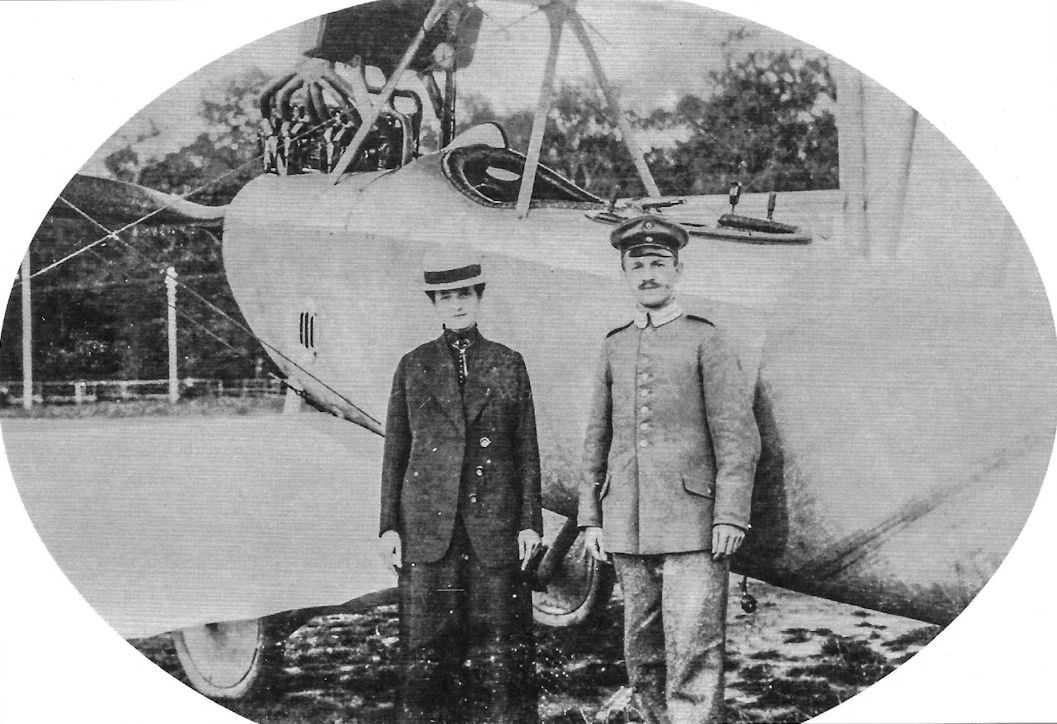
A couple pose with a DFW C.IV; the locale favors a training aircraft. (Peter M. Grosz Collection/SDTB)
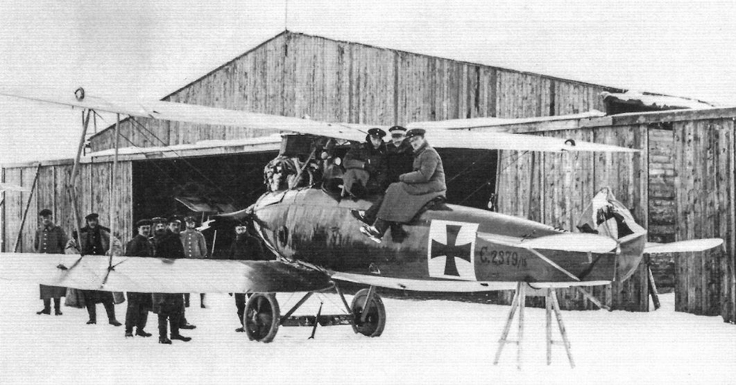
Men of FliegerAbteilung 14 on the Eastern Front pose for their portrait with DFW C.IV C.2379/16.The damaged rudder likely indicates the aircraft over-turned on landing. (Peter M. Grosz Collection/SDTB)
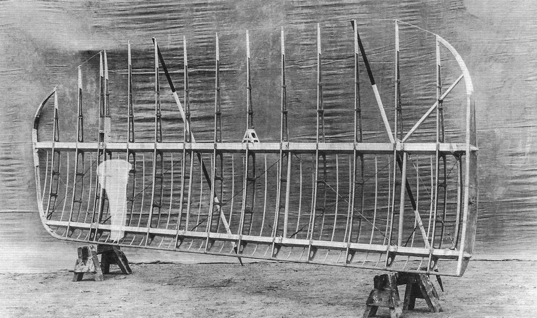
Uncovered lower port wing of a DFW C.IV, work number 492. (Peter M. Grosz Collection/SDTB)
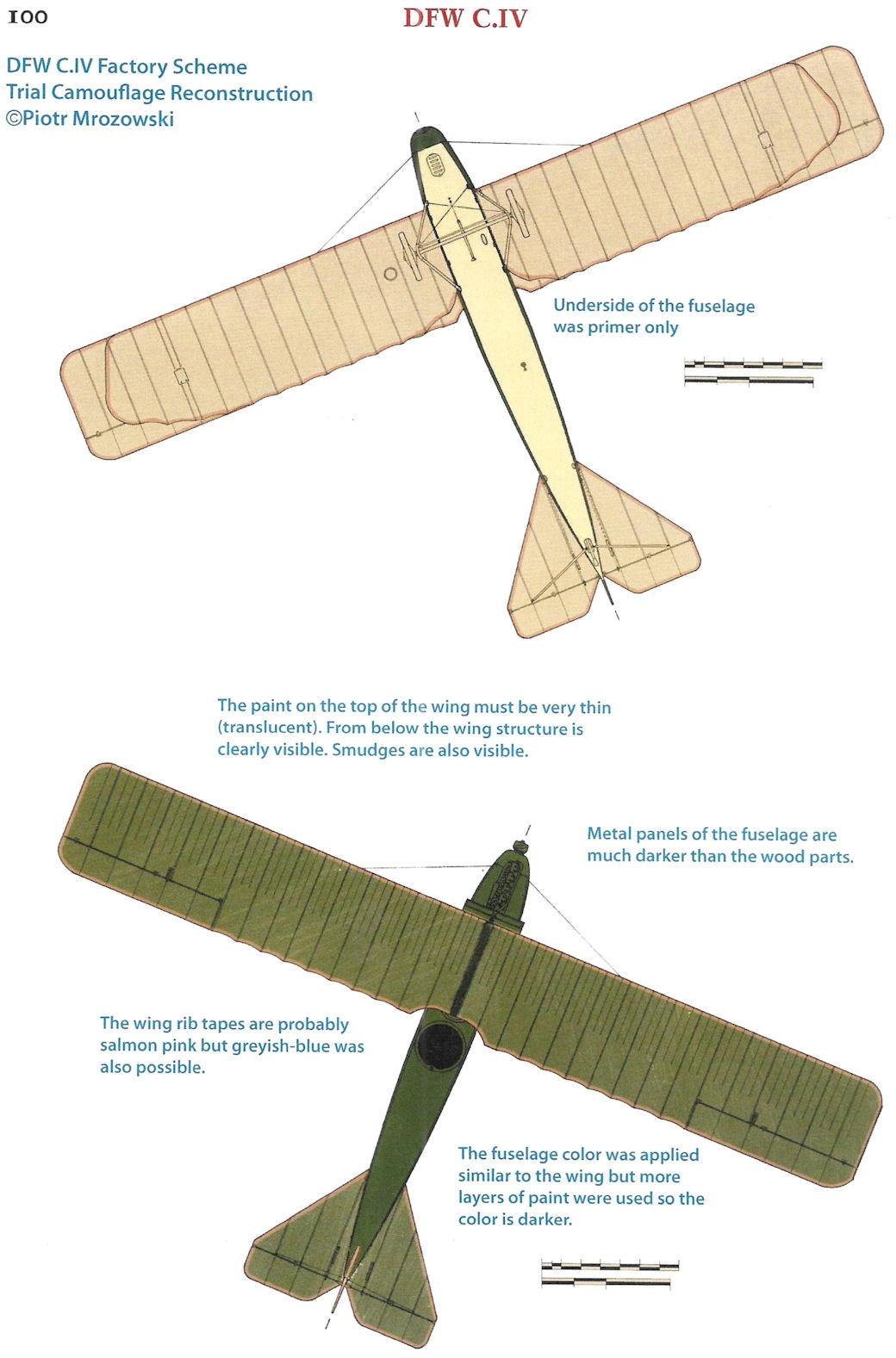
DFW C.IV Factory Scheme Trial Camouflage Reconstruction (c) Piotr Mrozowski
DFW C.IV
DFW C.IV
DFW C.IV
DFW C-Types
The DFW C.V was not just the most important DFW C-type, it was the iconic DFW. Built in far larger numbers than all other DFW designs combined, the C.V appeared at the front in late 1916 and from its arrival quickly became the backbone of the general purpose German two-seater units. The DFW C.V was such an excellent all-around aircraft, combining reliability with excellent handling qualities and maneuverability, that it was still the most numerous two-seater late in 1918.
In contrast to the excellent C.V, the other DFW C-types made no significant impact on the air war. The earlier production types, the C.I, C.II, and C.IV, were built and operated in very small numbers and made only a minor contribution to German aviation, being inferior to their competitors from Albatros and Rumpler. Their production orders and operational service was little-noted at the time, leaving only a sketchy record.
The later C.VI and C.VII did not see service. The C.VI was not placed in production and the C.VII arrived too late. What follows is the best information we have been able to uncover on these rare aircraft; hopefully more will turn up in the future.
DFW C.V
Without the DFW C.V, the DFW company would be a footnote in history as the producer of a variety of 'also ran' designs that sometimes supplemented the more successful designs with a few aircraft at the front. Of all DFW types, only the C.V was produced and operated in sufficient numbers to make a significant impact on the air war.
DFW hired Diplom-Ingenieur Hermann Dorner in July 1915 as technical director. Dorner, who had been working at the Adlershof Prufanstalt und Werft [PuW - test establishment and workshop), devoted much of his effort to the DFW R-plane projects. However, he also designed the DFW C.III and C.IV two-seat reconnaissance planes. According to an Idflieg letter of July 19, 1916, the C.III airframe was not strong enough due to the I-strutted wing cellule. This indicates that the C.III may be the single-bay tractor biplane with I-struts shown on page 99, although the DFW pusher C-type is generally considered to be the DFW C.III. Dorner was also part of the DFW C.V design team.
The development history of the DFW C.V is obscure. Most likely the C.V design was the product of a team of DFW engineers, including Heinrich Oelerich, Hermann Dorner, and Diplom-Ingenieur Willi Sabersky-Mussigbrodt, who had joined DFW January 1, 1916 and led the C.V design team. The C.V, internal factory designation T 29, had a light but strong airframe due to careful design, and incorporated the new 200 hp Benz Bz.IV engine that offered a useful power increase over the 150 hp Benz Bz.III used in earlier DFW C-types. The C.V mounted the standard C-type armament of a flexible gun for the observer and a fixed, synchronized gun for the pilot; in the C.V the pilot's gun was on the right.
The C.V's chief designer, Willi Sabersky-Mussigbrodt, recalled during an interview that the first flight of a C.V prototype was in May 1916. On July 11 the PuW reported that the new "DFW C-type with 200 hp Benz Bz.IV still has so many shortcomings ... the factory must demonstrate a new aircraft. The flight performance is up to expectations." However, C.V prototype C.3302/16 passed the load tests a few weeks later, on August 3rd and 4th, and on August 6th Idflieg reported "the performance figures achieved by the DFW 200 hp are very good... Sixty aircraft were ordered."
Production started immediately, and the first C.V aircraft reached the front in late September/early October 1916, by which time an additional 40 aircraft had been ordered. The DFW C.V must have made an excellent impression very quickly because in October the amazing total of 1,065 C.V aircraft were ordered! This number was so large that four different license manufacturers, Aviatik, BFW, Halberstadt, and LVG, had to be brought into the DFW C.V production program to deliver the aircraft ordered. The BFW contract was later cancelled, but production examples from the other three license manufacturers all passed their type tests in early February 1917. Soon after that the inventory of DFW C.V aircraft at the front jumped to become the most numerous C-type at the front by the end of April, and by the end of August reached 1,057 aircraft! And despite introduction of newer designs, the C.V remained in production until the Armistice and remained the most numerous C-type at the front.
Why did the DFW C.V quickly replace the Aviatik C.II and other competing C-types in production? In particular, the Aviatik C.II was already in production using the same engine and structural technology as the DFW C.V; why take the time to change production over to the DFW when Aviatik already had a similar internal design in production?
The key to the success of the DFW C.V was its excellent handling and maneuverability combined with a robust structure able to endure rough use in the field. Although its modest speed and good climb were surpassed by later German C-types, the C.V was effective, reliable, and able to defend itself throughout the war.
By late 1917 Allied fighters certainly had a speed advantage over the C.V and could often intercept it, but that did not mean they could shoot it down. An impressive example occurred on 12 December 1917, when James McCudden intercepted a DFW C.V. McCudden was a leading British ace, likely the highest scoring British ace of the war in that more of his claims can be definitely confirmed by wrecked aircraft than any other British fighter pilot. He was eventually credited with 57 victories, and by the date of this combat had 45 confirmed victories.
In any case, McCudden was flying his SE.5a, the best all-around British fighter to see widespread service, and on this day sighted a DFW C.V returning to German lines at 4,000 feet, just under an overcast. Leaving the rest of his flight above the clouds to intercept the C.V if it tried to escape into the clouds, McCudden dived to the attack. But the experienced C.V crew did not try to escape; instead, they stayed down to fight McCudden. Their confidence in their C.V and themselves was justified; they fought McCudden for fully five minutes, but he simply could not gain a favorable attacking position. According to McCudden, "EA put up a most determined and skillful fight and I was not able to use his blind spots for a single second. Moreover, the enemy gunner was shooting very accurately and making splendid deflection, so that when I got down to 500 feet I left the EA who went north over Bourlon Wood." McCudden realized that he and his SE.5a had met his match in this particular two-seater crew and aircraft. "The Hun was too good for me and shot me about a lot. Had I persisted he certainly would have got me for there was not a trick he did not know."
This is a remarkable tribute to the DFW C.V and its crews from a remarkable adversary, and demonstrated that the DFW had the maneuverability and handling qualities to defend itself against the best Allied fighters. With such an excellent aircraft, combat results came down to the crew.
Understandably in light of its prolonged production, the C.V underwent some evolution during is manufacturing life. Early aircraft featured ear radiators, spinners, and full engine cowlings. The major change in production was replacement of the ear radiators with more effective leading edge radiators with lower drag and improved reliability. Different manufacturers applied somewhat different camouflage and markings, and pre-printed camouflage fabric was used on later aircraft. In the field the upper engine cowling was often removed during warm weather, and at times the propeller spinner was also omitted in hot weather for better cooling.
Finally, a training version, the DFW C.Vc, was developed. This version used the 185 hp NAG C.III engine that was a little longer than the Benz Bz.IV, requiring a lengthened cowling. The NAG became available in mid-1917 and a total of 515 C.Vc trainers were ordered from October 1917. The 'c' suffix in the designation stood for 'Conrad', designer of the NAG engine.
DFW C.V Production Orders
Year Mon. Manufacturer Qty Serials Notes
1916 Aug. DFW 60 C.3300-3359/16 Includes prototypes 3300-3302/16
Sep. DFW 40 C.3400-3439/16
Oct. DFW 240 C.4800-5039/16
Oct. LVG 250 C.5040-5289/16 Type-test February 1917
Oct. Halberstadt 75 C.5750-5824/16 Type-test February 1917
Oct. Aviatik 150 C.5825-5974/16 Type-test February 1917
Oct. LVG 50 C.7650-7699/16
Oct. BFW 300 - Cancelled
Nov. Aviatik 100 C.9005-9104/16
1917 Jan. Aviatik 100 C.100-199/17
Jan. DFW 150 C.750-899/17
Feb. Aviatik 100 C.2000-2099/17
Feb. LVG 100 C.2100-2199/17
Feb. Halberstadt 25 C.2500-2524/17
Apr. Halberstadt 50 C.33 78-3427/17
Apr. Aviatik 200 C.3800-3999/17
Apr. DFW 150 C.4578-4727/17
May DFW 200 C.6000-6199/17
Jul. Aviatik 150 C.6900-7049/17
Jul. DFW 200 C.7750 7949/17
Oct. DFW 15 - Type C.Vc, serial numbers unknown
1918 Jan. DFW 300 C. 17000-17299/17 Type C.Vc
Feb. Aviatik 150 C.200-349/18
Feb. DFW 150 C.350-499/18 Some fitted with NAG engines
Mar. Aviatik 150 C.2150-2299/18
Mar. DFW 150 C.2300-2449/18
Jun. Aviatik 100 C.4300-4399/18
Jun. DFW 100 C.4400-4499/18
Jun. Aviatik 100 C.4500-4599/18
Jun. Aviatik 50 C.6750-6799/18
Jul. DFW 50 C.8000-8049/18
Jul. Aviatik 200 C.8200-8249/18
Nov. DFW 200 - Type C.Vc, serials unknown
Summary: 3955 total aircraft ordered - DFW: 2005; Aviatik: 1400; LVG: 400, Halberstadt: 150
DFW C-Type Specifications
DFW C.IV DFW C.V DFW C.VI DFW C.VII
Engine 150 hp Benz Bz.III 200 hp Benz Bz.IV 220 hp Benz Bz.IVa 220 hp Benz Bz.IVa
Span, Upper 13.30 m 13.27 m 13.60 m 13.60 m
Span, Lower - 12.80 m - -
Chord, Upper - 1.75 m - -
Chord, Lower - 1.75 m - -
Gap - 1.80 m - -
Wing Area 42.2 m2 41.52 m2 - 38.0 m2
Length 7.90 m 7.88 m 7.50 m 7.0 m
Height 3.3 m 3.26 m - 2.8 m
Empty Weight 720 kg 1,027 kg - 800 kg
Loaded Weight 1,230 kg 1,477 kg - 1,230 kg
Maximum Speed 135 km/h 155 km/h - 160 km/h
Climb to 1,000m - 4.0 minutes - 3.0 minutes
Climb to 2,000m - 7.0 minutes - -
Climb to 3,000m - 15.0 minutes - -
Climb to 4,000m - 25.0 minutes - -
Climb to 5,000m - 40.0 minutes - -

DFW C.V C.3xxx/16 of Schusta 8, July 1917 at Mousay Aerodrome. The stylized "W" is the unit insignia.

DFW C.V 4918/16 of Flieger-Abteilung (A) 276.

DFW C.V(LVG) 5159/16 tactical '2' of FliegerAbteilung (A) 211.

Early production DFW C.V of an unknown unit.

DFW C.V of Flieger Abteilung 48.

DFW C.V(LVG) tactical '6' of an unknown Schusta.

DFW C.V(LVG) of Flieger Abteilung 48. 1917.

DFW C.V C.4832/16 of Schusta 29b.

DFW C.V(Av) C.9034/16 of FliegerAbteilung (A) 208.

DFW C.V C.794/17 flown by 1. Marine Feld Flieger Abteilung, summer 1917.

DFW C.V C.799/17 tactical "7" of FliegerAbteilung 7 was brought down on 12 July 1917 by pilots of No.56 Sqdn, RFC.

DFW C.V(LVG) C.2164/17 with three-pointed star insignia from an unknown unit.

Rudolf Stark's DFW C.V 6022/17 in Bavarian Flieger-Abteilung (A) 296. The observer was Ltn.d.R. Helmo Ludovici.

DFW C.V(Av) C.287/18 of Flieger-Abteilung (A) 219, May 1918.

DFW C.V(Av) C.287/18 of Flieger-Abteilung (A) 219, May 1918, after capture, assigned capture number G/HA/4, and over-painting of the German insignia by British cockades.

DFW C.V 4430/18 of Flieger-Abteilung (A) 286b, May/June 1918. The unusual symbol was the unit marking and was copied from the emblem of a brewery.

DFW C.V Gretel / Lo of Flieger Abteilung (A) 239, mid 1918.

DFW C.V Hede flown by Feldwebel Henkel and Lt. Henschel of Flieger Abteilung (A) 253, late 1917. Hede was the name of their mechanic.

Factory finish applied to Halberstadt-built C.V aircraft when fuselage was stained.

DFW C.V(Halb) tactical "1" of FliegerAbteilung 44.

DFW C.V with streaked camouflage if Flieger-Abteilung (A) 199b; crew and serial number unknown.

DFW C.V flown by Lt. Bastian of 1. Marine Feld Flieger Abteilung.

DFW C.V(Av) serial unknown of Flieger Abteilung (A) 208.

Late production DFW C.V of an unknown unit, 1918. The aircraft wears late 1918-style markings and striped finish.

DFW C.V of KG 2.

DFW C.V C.7897/17 Wanda of the postwar Polish Air Service. The crew was Sergeant pilot Kazimierz Burzynski and observer Colonel Wladyslaw Anders, 12 Eskadra Wywiadowcza.

DFW C.V of the Polish Air Service in 1920 flown by pilot Sgt. Wiktor Daniel & observer CpI. Mieczyslaw, III Eskadra Wielkopolska. One of 30 aircraft built for Poland as passenger planes, it was one of several adopted for combat in Poland with a Spandau for the pilot and a Lewis for the observer.

DFW C.V of the Polish Air Service post-war.

DFW C.V of the Estonian Air Service post-war.

DFW C.V of the Latvian Air Service, 1924.

DFW C.V of the Czech Air Force School, Cheb Aerodrome, ca. 1921; colors not confirmed.

DFW C.V C.3311/16 was a C.V prototype or early production aircraft with ear radiators. The propeller lacks a spinner but the other C.V identification features are present. This photo became Sanke card 1042.
Early version of the DFW C.V produced in August 1916; assigned to Fl.-Abt.(A) 252w in April 1917. Note the housing around the engine.
Early version of the DFW C.V produced in August 1916; assigned to Fl.-Abt.(A) 252w in April 1917. Note the housing around the engine.

A prototype DFW C.V in front of the DFW factory. The first three prototype C.V aircraft are thought to have serials C.3300-3302/16, the first three serials from the first production batch of 60 aircraft ordered from DFW. The C.V was a sturdy, two-bay biplane powered by a 200 hp Benz Bz.IV. The prototypes and early production aircraft featured ear radiators; later production aircraft had a leading edge radiator for improved reliability and reduced drag.

DFW C.V(LVG) 5159/16 tactical '2' of Flieger-Abteilung 64/211.This early-production aircraft has ear radiators. (Bruno Schmaling)


DFW C.V(LVG) 5055/16 tactical '4' of Flieger-Abteilung (A) 211. The dark fuselage band appears to be the unit marking.

This DFW C.V(LVG) 2125/17 of Flieger-Abteilung (A) 254 was flown by the commanding officer, Rittmeister Elard Freiherr von Loewenstern. The aircraft carries a version of the Loewenstern Wappen (family crest) as its insignia.

Closeup photo of the Loewenstern Wappen on DFW C.V(LVG) 2125/17.

The crew Tirnstein and Schorling in front of their early-production DFW C.V The long exhaust pipe was probably fitted to help reduce the engine noise and exhaust glare during dusk or early night bombing missions.

LVG C.VI 5040/16 (later rationally re-designated DFW C.V(LVG)) at Adlershof for its type test in February 1917.

LVG-built C.V in brush-applied three-color camouflage.

Views of early-production DFW C.V(Av) 5927/16 in British hands. The Aviatik logo was added to the center of the rudder cross, the interplane struts, and other parts on Aviatik-built C.V machines. This machine was brought down on the 24 April 1917, near Les Facons, by Flt. Sub. Lt. Little, No. 8 Squadron, RNAS. Given capture designation G.24, it was flown to the UK on 11 May and flight tested. The report on this aircraft indicated "the tops of the planes and the top of the fuselage are all camouflaged green and brown."


Early production DFW C.V reconnaissance planes with rounded ear radiators at Feld-Flieger Abteilung 8b. Racks for light bombs are visible under the fuselage center section of the C.V in the foreground.

Mechanics run up the engine of this DFW C.V of Flieger-Abteilung 48 wearing an artillery grenade insignia.

This DFW C.V of Flieger-Abteilung (A) 255 has a large star insignia and carries identification pennants attached to the lower wings.

DFW C.V(Av) of Bavarian Flieger-Abteilung (A) 287 in 1918.The pilot is Gefreiter Heinrich Muller and the observer is Lt. Willy Wolff. This late-production C.V has no spinner and the flying surfaces are covered with printed camouflage fabric. Aviatik-built C.V aircraft had the Aviatik logo in the center of the rudder cross as visible here.

This photo of a late-production DFW C.V in 1918 insignia shows the details characteristic of late-production aircraft; no spinner, leading edge radiator, and engine with only partial cowling panels. A paper label with the rigging diagram is fastened at the front side of the fuselage. The unit and crew are not known.

Colorful DFW C.V in 1918 insignia; unfortunately, no information about the crew, unit, or location is available. Only the Ernst Wolff exhaust type 41 for the engine suggests the aircraft was built by LVG.

DFW-built C.V Lolo of Flieger-Abteilung (A) 208 at Voyenne Aerodrome in early 1918. The reversed swastika apparently was the unit insignia; it represented good luck in these pre-Nazi days. In this unit the aeroplane names were taken from racing horses, not from girls or comrades as was more common.

DFW C.V(Av) of Flieger-Abteilung (A) 212 in Aviatik three-color camouflage with an arrow personal insignia.

DFW C.V(Av) C.6990/17 on the Brest-Litowsk aerodrome about to accept an impressive amount of mailbags for delivery to Luzk, Berditschew, and Kiew (Kiev) in early 1918.

DFW C.V(Av) C.6990/17 on the Brest-Litowsk aerodrome about to accept mailbags for delivery to Luzk, Berditschew, and Kiew (Kiev). This service was inaugurated in early 1918 to serve the large area of Russia then occupied by German troops.


Late-production DFW C.V 4475/18 captured in the Middle East has printed camouflage fabric on all flying surfaces with the exception of the white-painted rudder.
Late-production DFW C.V 4482/18 captured in the Middle East has printed camouflage fabric on all flying surfaces with the exception of the white-painted rudder. It was from the same production batch as 4475/18; both were ordered in June 1918. An F.K.8 is in the background.

More views of late-production DFW C.V 4482/18 captured in the Middle East with printed camouflage fabric on all flying surfaces and white-painted rudder.The light colored fabric sewn over the wing ribs and ribs on the tail and the late national insignia are distinctive. In these images the upper cowling panels have been removed. For a design that reached the front in late 1916, the fact that new production machines were ordered in mid-1918 and still being delivered to the front as first-class combat aircraft in later 1918 is a remarkable tribute to the type's overall excellence. Newer types were faster but did not surpass the DFW C.V in maneuverability and excellent handling qualities.

DFW-built C.V tactical '2' of Flieger-Abteilung (A) 208; it has leading-edge radiators.

DFW-built C.V tactical '3' of Flieger-Abteilung (A) 208 in July 1917; it has leading-edge radiators and a non-standard ladder and hand-hold on the fuselage side. The pilot was Uffz. Zenker and the observer was Lt. Wesener. (Reinhard Zankl)

Aviatik-built DFW C.V apparently belonging to Flieger-Abteilung (A) 209.

DFW C.V(Av) tactical '7' of Flieger-Abteilung (A)211.The tactical number has a white outline and the aircraft has a leading-edge radiator. (Bruno Schmaling)

DFW C.V(Av) tactical '5' of FliegerAbteilung (A) 211. The tactical number has a white outline and only the upper portion of the rudder is painted white as a background for the national insignia. It has a leading-edge radiator. (Bruno Schmaling)

LVG-built DFW C.V(LVG) 7689/16. The spray-painted camouflage is in stark contrast to the printed camouflage fabric applied to all flying surfaces of the aircraft built in 1918.

DFW C.V in 1918 national markings in the field.

DFW C.V(Av) with moon and star insignia. Although the texture of the photo gives the impression of the typical Halberstadt finish, the engine louver design was unique to Aviatik, identifying this C.V as Aviatik-built.

DFW C.V 790/17 hede was flown by Feldwebel Henkel (in the center with walking stick) and observer Lt. Hentschel, who stands in the rear cockpit.This crew bolstered their aircraft's firepower by mounting a captured Lewis gun to the center section struts so the observer could fire forward above the propeller arc. Standing at left is Monteur Hede (whose name adorns the machine) and on the right is Monteur Lucka. The white circle just visible behind the pilot Henkel was the unit marking of FliegerAbteilung (A) 253.

Two views of late production DFW C.V(Av) C.2210/18 in 1918. The photos clearly show the four-color printed camouflage fabric applied to all flying surfaces.

DFW C.V of Flieger-Abteilung (A) 232 with a reversed swastika, white fuselage band, and tactical number '3'. This C.V was brought down on 26 July 1918 by pilots of No.24 Sqdn., RAF; Lt. H.D. Barton, Lt. Farrell, Lt. Palmer, Lt. J. Miller, and Lt. Passmore.The pilot, E. Bolgihn, and observer, H. Neuendorf, were unharmed and made PoW.

DFW C.V tactical number '7' is thought to be C.V C.4686/17 that was captured by the British and given captured aircraft number X.G.13. The white circles may be patched bullet holes. A leading edge radiator is fitted. A sample of the fabric from this aircraft is kept in the IWM; the deep green applied to the canvas gives a strong dark greenish-blue appearance.

DFW-built C.V of Flieger-Abteilung (A) 212 was painted in dark greenish-blue camouflage colors.

Rudolf Stark's DFW C.V 6022/17 in Bavarian Fl. Abt. (A) 296. Stark flew for a long time with observer Ltn.d.R. Helmo Ludovici. Stark had applied for transfer for fighters, but waited until Ludovici received his own transfer to flying school. Ludovici would later fly as a fighter pilot under Stark's command in Jasta 35b. Stark scored 11 victories as a fighter pilot.

Observer Ltn.d.R. Helmo Ludovici gets some assistance with his flight gear; the DFW C.V 6022/17 "L" he and Rudolf Stark flew while with Bavarian Fl. Abt. (A) 296 is in the background.

Lt. Rudolf Stark in front DFW C.V 6022/17 "L" he and Helmo Ludovici flew while with Bavarian Fl. Abt. (A) 296.

Lt. Rudolf Stark taxiis DFW C.V 6022/17 "L" he and Ltn.d.R. Helmo Ludovici flew while with Bavarian Fl. Abt. (A) 296. The black and white chessboard marking on the fin was the unit marking.

DFW C.V(LVG) 5262/16 with a memorial wreath to be dropped in honor of Rudolf von Eschwege, who was KIA on 21 November 1917 when he attacked a British balloon that had been booby-trapped with explosives. Eschwege was credited with the decoy balloon for his 20th victory.The photo was taken at Drama, Macedonia.

DFW C.V(Halb) of Feld FliegerAbteilung 4 on the Eastern Front, being readied for its next mission.

DFW C.V 2379/18 on display in France after being downed by Lt. Putnam, USAS, on 22 August 1918 at Raulecourt.

Late-production DFW C.V with 1918 markings outside an airship hangar. A Salmson 2 appears to be in the background, indicating the photo was taken postwar.

DFW C.V 4430/18 of Bavarian FliegerAbteilung (A) 286 in May/June 1918. The camouflage is standard for this production batch with printed camouflage fabric on the flying surfaces and grayish-magenta and olive paint on the fuselage. The interesting symbol is copied from the logo of a Bavarian brewery and was the unit marking.

DFW-built C.V Alice of Flieger-Abteilung 43 in 1918. The pilot was Vzfw. Egon Fath (at right) and the observer was Lt. May. The aircraft has a comet insignia and a rack on the fuselage side for Wurfminen or Fliegermaus for ground attack.

DFW-built C.V of Schusta/Schlasta 10 in 1918 insignia. The black number was painted on the bottom of the lower right wing underside (between fuselage and cross). The name Elli was painted in script below the cockpit (it is barely visible in this print) and three bullet holes in the fuselage were circled and the date of the damage was noted; see enlarged photograph at left. The combat damage occurred in 1917 and the bullet patches and date survived the national insignia being repainted in the 1918 style.
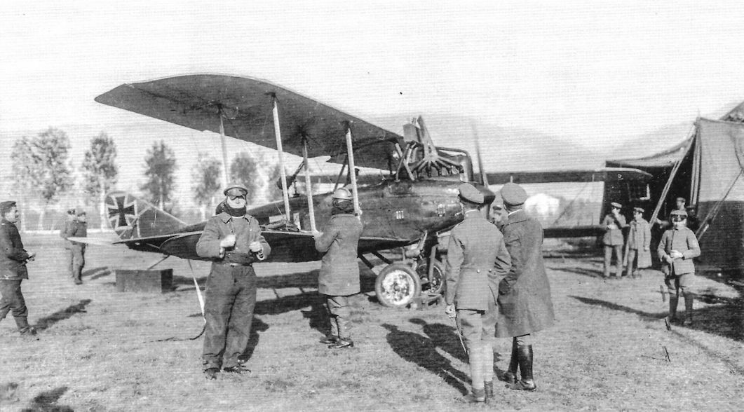
DFW-built C.V on the Piave Front in Italy.

DFW-built C.V Lo-Gretel of Flieger-Abteilung (A) 239 in 1918 markings.This later-production aircraft has a leading-edge radiator and no spinner. (Lower photo Reinhard Zankl)


DFW C.V of Uffz. Scholz and Lt. Lange with a Totenkopf (death's head) insignia on the fuselage. Black and white recognition pennants are attached to each lower wing. The photo was taken in early 1918.

DFW C.V 799/17, tactical number '7' of Flieger-Abteilung 7, was shot down and captured intact by Keith Muspratt and Arthur Rhys Davids of 56 Squadron, RFC on 12 July 1917. It was given the captured aircraft reference number G53.The leading edge of the upper wing was damaged in the crash-landing. The white arrow was the unit insignia of Flieger-Abteilung 7. This aircraft, fitted with leading edge radiator, was one of a batch of 150 ordered from DFW in January 1917. The notes of the British intelligence report gives the colors as: "The fuselage is built up of 3 ply and is marked on top and on each side about halfway between the passenger's seat and the tailplane with white arrows pointing towards the front of the machine and about 3 feet long. The figure "7" is painted on each side of the fuselage in black. Planes (wings) coloured white below and light green on top." The report gives the serial number erroneously as 788/17 but this was corrected by hand. Unfortunately, the fuselage colors are not given in the report. The front and side views show the national insignia under the lower wings had no white outline as did the other insignia.


The observer of this DFW C.V demonstrates the long focal-length Foigtlander Flieger Kammer (Flight Camera) FK IV 125 cm camera that has been fitted.

DFW C.V tactical '3' with ground crew.

DFW C.V(Av) of Flieger-Abteilung 6; the pilot was Ulrich.

DFW C.V(Av) with flight and ground crew in 1918. Signal flares are mounted on the fuselage, an anemometer is attached to the interplane strut, and a generator is mounted on the starboard under-carriage strut.

DFW C.V(Halb) C.3420/17 of Flieger-Abteilung 15 with Josef Fritz and airmen. The distinctive camouflage is the same as that Halberstadt applied to their own CL.II.

Aviatik-built C.V of Flieger-Abteilung (A) 208; the observer was Lt. Muller. The compass was in the lower left wing.

DFW C.V 2392/18 with ground crew and CO, probably from Kampfstaffel 8. This late-production C.V has its flying surfaces covered in four-color printed camouflage fabric. Individual markings of three white chevrons are partially visible. The flare pistol fitted to the fuselage side is the Fieraufige Leuchtpistole Erdmann Systeme.

Enlargement of the Fieraufige Leuchtpistole Erdmann Systeme flare pistol fitted to the fuselage side of DFW C.V 2392/18. More about this semiautomatic flare pistol is described in Waffen Revue Nr. 12, March 1974.

Photos of an Aviatik-built DFW C.V and its crew of an unknown unit in 1918. The crew's names are not known but the dog appears in all three photos and was clearly a crew member. The second foot step below the pilot's cockpit was typical of Aviatik-built C.V aircraft; note the Aviatik logo decals on the struts and rigging label glued to the fuselage. The aircraft has two-tone sprayed camouflage finish on the fuselage and lozenge printed camouflage fabric on the wings.


This DFW C.V of Flieger-Abteilung(A) 248 carries a checkerboard personal insignia. (Bruno Schmaling)

Rudolf Stark (at right) and observer Ltn.d.R. Helmo Ludovici in front of their DFW C.V 6022/17 in Bavarian Fl. Abt. (A) 296.

Rudolf Stark in front of DFW C.V 6022/17 "L" in Bavarian Fl. Abt. (A) 296.

Views of a late-production DFW C.V with leading-edge radiator and Totenkopf (death's head) fuselage insignia flown by Flieger-Abteilung (A) 199b.

DFW-built C.V of FliegerAbteilung (A) 239. The teddy bear attached to the front inner strut on the right wing was a good luck mascot.

A pristine Aviatik-built DFW C.V with Axial propeller of an unknown unit.

DFW C.V(Av) with its crew. The designation D.F.W. C.V(Av.) is stenciled on the engine cowling. A rack of signal flares is attached to the fuselage within easy reach of the observer. This later-production aircraft has the leading-edge radiator.
The DFW C.V built by Aviatik under license was initially known as the Aviatik C.IV before being re-designated the DFW C.V(Av) as seen painted on the nose of the DFW C.V here. DFW C.Vs built by Halberstadt were initially known as the Halberstadt C.I or C.IV before being re-designated the DFW C.V(Halb), and those built by LVG initially were known as the LVG C.VI before being re-designated the DFW C.V(LVG).
The DFW C.V built by Aviatik under license was initially known as the Aviatik C.IV before being re-designated the DFW C.V(Av) as seen painted on the nose of the DFW C.V here. DFW C.Vs built by Halberstadt were initially known as the Halberstadt C.I or C.IV before being re-designated the DFW C.V(Halb), and those built by LVG initially were known as the LVG C.VI before being re-designated the DFW C.V(LVG).

Introduced in late 1916, the DFW C.V was still in front-line service in 1918. Although the most common aircraft in Luftstreitkrafte service, the example above, likely C.5967/17, is a rare night-bomber conversion, one of probably only four C.Vs thought to have been modified for this role. Six 50 kg P.u.W. bombs are carried, the number required by the Idflieg specification for single-engine night bombers, later to be designated N-types.The modifications included small navigation lights on both forward outer wing struts and likely the tail, the wing covering between two ribs on the lower starboard wing removed for the bomb sight on the fuselage, and the bomb sight. The black tube behind the bomb sight may be a night vision bomb sight (tested by German bomber units during WWI). The circular object mounted on the cabane is an altimeter. On the inner right front interplane strut under the Morell air speed indicator may be an additional Fernfahrtmesser (compass) for night flying. One landing light was mounted under the front fuselage. The white thunderbolt fuselage insignia indicates operational use; in this case, the aircraft was assigned to Bogohl 5.

DFW C.Vc 17094/17 at Romorantin in 1919 carries the final form of the national insignia. The longer NAG engine of the C.Vc required a slightly extended nose.

Another view of DFW C.Vc 17094/17 at Romorantin in 1919. Standing in front of the DFW is American test pilot Leigh Wade. In April 1924 Wade participated in the "World Flight" by the US Army's Douglas World Cruisers.

DFW C.Vc 17077/17 at the Berlin DSL museum between the wars. By then the aircraft was painted black.

DFW C.Vc 17077/17 after the initial stage of restoration at the Muzeum Lotnictwa Polskiego in Krakow, Poland, in May 2000.There is a discrepancy somewhere; the DFW C.Vc aircraft had NAG engines and this example appears to have the standard Benz Bz.IV engine. Perhaps the documentation specifying the serial number is incorrect? The Bork i Mark indicates repair on 19-6-1918, K.No. 473. (All photos (c) Piotr Mrozowski)


Why is this C.V black? Piotr Mrozowski started to study this aircraft before restoration and concluded:
Originally this aircraft was painted in two color camouflage: Greyish-violet and light olive-green. It is seen in his photos taken before restoration.
The next layer of paint, dark bluish-grey, was very probably applied after repair in Bork i Mark).This color is seen at the side of the engine cover repair and in color photos kept in ECPA Paris.
The last paint, black, was added after WWI at the Berlin DSL museum. Very probably the dark bluish-grey color confused the technicians and they decided to paint it black because they wanted a German night bomber in the collection. The black paint was visible on parts added after WWI. But of course we can't eliminate the possibility that BiM converted this aircraft into the night version during WWI.

Close up of the tail area at the fuselage, under the horizontal stabilizer the original light olive green color is seen.

Close up of the observer's cockpit. The metal cover over the control cables is in original paint. The light yellowish-brown color was characteristic for most of the metal parts inside the cockpits.

The exhaust name plate from DFW C.Vc 17077/17 at Krakow states that the exhaust was produced by Max Hirschfelder, Berlin-Weissensee company. License No. 122 special for DFW C.V with Benz 200 hp engine.The C.Vc model had the NAG engine, so the C.V on display was probably not a C.Vc. Max Hirschfelder was one of many German companies producing aircraft components. (©Piotr Mrozowski)

DFW C.V(Av) 287/18 of FliegerAbteilung (A) 219 force-landed behind British lines on 31 May 1918. In this photograph the aircraft is still wearing its original markings. A color photo from the ECPA collection shows C.V(Av) 271/18 in two-tone sprayed camouflage, greyish-violet and olive green on the top, light yellow on the bottom. The interplane struts were painted light grey. DFW C.V(Av) 287/18 is from same production batch and almost certainly was in the same camouflage. The over-paint around the Balkenkreuze was a bright dark green.

DFW C.V(Av) 287/18 after British cockades were painted over the German national insignia and the British tracking designation G/HQ/4 was applied.This is a good example of a late-production C.V with leading edge radiator and no cowling over the cylinder head.

Another photograph of DFW C.V(Av) 287/18 after British cockades were painted over the German national insignia and the British tracking designation G/HQ/4 was applied.

More views of DFW C.V(Av) 287/18 after capture by the British. The photograph shows the aircraft after cockades were painted over the German national insignia and the British tracking designation G/HQ/4 was applied.

DFW C.V(Av) 287/18 after British cockades were painted over the German national insignia; the butterfly insignia is barely visible. The clean lines of the C.V show clearly, as does the leading edge radiator and exposed cylinder head.
DFW C.V(Av) 287/18 after British cockades were painted over the German national insignia. However, the butterfly insignia was left intact. An RE.8 is in the background.

More views of DFW C.V(Av) 287/18 after capture by the British. The photo shows the original German national insignia on the top of the upper wings showing some overpainting.

Well-known photo of DFW C.V(Av) C.5845/16; the Aviatik logo was applied to the struts of Aviatik-built C.V aircraft and center of the rudder insignia as shown. Signal flares are in a bracket just behind the observer's cockpit.

DFW C.V with Lt. Graf Fenster waving to the camera aircraft. This C.V was assigned to 1 Marine Feld Flieger-Abteilung and marked with a snake and light spinner; the pilot was Flugmeister Bartschis. The DFW C.V was the most numerous and important German two-seat reconnaissance aircraft of the war.
The DFW C.V was the best second-generation C-type general-purpose two-seater, being tough and maneuverable. Powered by the 200 hp Benz Bz.IV, more DFW C.Vs were built (3,955) than any other German warplane, and it served in large numbers until the armistice.
The DFW C.V was the best second-generation C-type general-purpose two-seater, being tough and maneuverable. Powered by the 200 hp Benz Bz.IV, more DFW C.Vs were built (3,955) than any other German warplane, and it served in large numbers until the armistice.

DFW C.V(LVG) of Flieger-Abteilung (A) 282 trails identification pennants as it flies over the front.The banded camouflage pattern was characteristic of LVG-built DFWs.

DFW C.V(LVG) in flight.The broad, three-color bands of camouflage paint identify this C.V as built by LVG. This photo was reproduced as Sanke card 1025 as shown.

The exuberant observer of this colorful but unidentified DFW C.V waves to the photographer.

LVG-built C.V aircraft tactical 3, 4 and 6 of an unknown Schusta loading on a train on moving day.

DFW C.V reconnaissance planes under construction in the DFW factory. The brilliant C.V was the only DFW type to make a name for itself in combat. Not only was it the most successful DFW type, it was built under license by Aviatik, Halberstadt, and LVG. A total of 3,955 were ordered, more than any other German warplane of the war. (Peter M. Grosz Collection/SDTB)

These two views of the Aviatik factory illustrate a key part of the DFW C.V story - the mass production of DFW C.V aircraft under license by Aviatik. The Aviatik C.II was a competitor of the DFW C.V; it used the same engine, the same basic technology, and appeared about the same time. After one production batch of 75 Aviatik C.II two-seaters, Aviatik was then directed to produce the superior DFW C.V under license. In fact, Aviatik was the largest manufacturer of the DFW C.V other than DFW itself. What was the reason for this outcome? While the Aviatik C.II was a robust aircraft like the DFW C.V and was even slightly faster, the C.V had far better maneuverability and handling qualities that made it a favorite of its crews. The DFW C.V had the element of inherent design quality that the Aviatik C.II lacked; this made the DFW C.V a great success story while the Aviatik C.II was but a footnote in that story.

Unpainted DFW C.V(Av) at the Aviatik factory undergoing gun testing.

DFW C.V(Av) aircraft at the Aviatik factory.

DFW C.V(Av) being spray-painted at the Aviatik factory.

Derelict DFW C.V(Av) 306/18 serves as a prop for this photograph of Allied troops.

Derelict DFW C.V(Av) 306/18 rests in a rail yard. The serial is over-size and the narrow 1918 national insignia is painted over a white background.

DFW C.Vc 17266/17 in the junk pile at Romorantin in 1919 carries the final form of the national insignia.

Later-production DFW C.V aircraft with leading-edge radiators in Bulgarian service.

Later-production DFW C.V aircraft in 1918 Bulgarian service.The 100 kg P.u.W. bomb was likely not carried by the DFW but was intended to make the photos more menacing!

The Bulgarian DAR factory built a version of the C.V as their U-1. The Bulgarian civil registration is carried on the clear doped wings and ply fuselage. The national colors of white, green, and red are carried on the rudder with white leading. On the fin of B-BATO the round manufacturer's badge can be seen. Around the white circle is run the text - Darzhavna Aeroplanna Rabotlinitsa - in Cyrillic characters. The shield under the cockpit is in the Bulgarian national colors.

DFW C.V at Cheb airfield at the Czech Air Force School about 1921. A Breguet 14 is in the left background.

This early-production DFWC.V with side radiators and white fuselage stripe landed by mistake in the Netherlands in July 1917. The photo above shows it being dismantled for transportation, and below it is a closeup with the wings already removed.

DFW C.V LA 46 in Netherlands service.

DFW C.V(LVG) ex-LA47 in Netherlands service photographed on March 9, 1918. The pilot is Kpt. V.L. Van Heijst and the observer is the Dutch Minister of War.

DFW C.V in Netherlands service post-war.

A DFW C.V in Finnish national markings, photographed at Utti air station in the summer of 1918. Hannelius in the cockpit and Ehrnrooth leaning on the airscrew, (via K Stenman)

To the left of this Finnish Nieuport 23 is the nose of a DFW C.V in Finnish national markings after the war.

Finnish DFW C.V serial 2A.351 (formerly C.57/18) photographed in winter at the Aviation Battalion at Santahamina.This aircraft survived until 11 February 1921, when the pilot, L.F. Saukkonen, stalled it at 40 metres and was killed in the resulting crash. It was written off a year later on 25 January 1922. These aircraft all had the late-production leading-edge radiators, (via K Stenman)

The two DFW C.Vs were received from Germany wearing their German national markings. The wings were in lozenge fabric. The machines were sent by train on 26 March 1918, from Vaasa to Antrea where Flying Detachment II was to be established. They were given the serials C56/18 and C57/18. (via K Stenman)
DFW C.V at left and BE.2 at right in Estonian service after the war.

DFW C.V 6181/17 in postwar Polish service.

DFW C.V 5028/18 in postwar Polish service.The usual wheels have been replaced by skis for the winter snow.

One of the 30 DFW C.V aircraft built for Poland, here armed in Poland with Lewis on TO3 and Spandau. The crew was sergeant pilot Wiktor Daniel and corporal observer Mieczyslaw Serdecki, March 1920.

DFW C.V C.7897/17 nr.2.The name "Wanda" was added during the Polish-Russian war. The crew of sergeant pilot Kazimierz Burzynski and observer colonel Wladyslaw Anders are shown just after returning from a combat sortie deep over enemy lines. (All photos on these two pages courtesy Tomasz J. Kopanski.)

The nose of DFW C.V C.7897/17 nr.2 with double emblems of 12 Reconnaissance Squadron (12 Eskadra Wywiadowcza) (the lightning bolt) from previous service and later honorable badge (White Eagle holding in its clutches the sash with motto “ZA OBRONE KRESOW WSCHODNICH" - "FOR TH E DEFENCE OF EASTER") introduced in June 1919, after the end of the Polish-Ukrainian war. The badge was originally a silver plaque attached to the side of the plane; later the painted form was more popular. The Bork and Mark repair plate indicates that this machine was repaired/renovated, during WWI in the DFW repair center Markische Flugzeugwerke (M.F.W.), Bork.

DFW built 30 C.V aircraft for Poland as passenger planes.

The rudder of an LVG-built DFW C.V shot down 30-5-1918 as the first victory of Marcel Guillet of SPA 163. The rudder had been repainted green in the field using a different shade than the original LVG factory finish, which is still faintly visible under the green applied in the field.

Remains of DFW C.V (serial unknown) from FA(A) 232, shot down 23 November 1917 by Capitano Bartolomeo Costantini (his 3rd confirmed victory) from 91a Squadriglia. The crew, Uffz. Krauser and Lt. Strathmann, were both KIA. This aircraft was DFW-built (characteristic "C" is seen). Two colors are visible. The first is chestnut brown and the other is a yellowish olive. The fuselage plywood was initially covered by an ivory undercoat lacquer, then small dots (similar to the Halberstadt-type camouflage pattern) were applied. The border between colors is very hazy. (Photos courtesy: Museo Francesco Baracca)

Pieces from DFW C.V(Av) C.3955/17 from FA(A) 204 shot down on 7 November 1917 by Capitano Francesco Baracca (as his 27th confirmed victory) shared with Tente Giuliano Parvis (as his 5th confirmed victory). The crew, Gefr. Wilhelm Appelt and Lt. Paul Wilkening, were both KIA. Fuselage plywood and rudder fabric with characteristic Aviatik font style serial number is seen. The colors (olive brown and light greyish brown) are sprayed directly on the plywood and canvas; no undercoat was used. (Photos courtesy: Museo Francesco Baracca)

Fuselage fabric from the DFW C.V at Krakow. The photo was taken during the DFW C.V restoration. This close up shows the upper part of the fuselage near the observer's gun ring. The greyish-magenta and olive green traces are visible. (Photo (c) Piotr Mrozowski)

Composite photo showing both sides of a DFW C.V fuselage air vent and hinge details. Component from DFW C.V C.17077/17 Note the BiM repair and dark greyish-blue paint traces. In center is an enlarged fragment with number 30591; it could be the aircraft Werke Nummer.
(©Piotr Mrozowski)
(©Piotr Mrozowski)

Part of the instrument panel of the DFW-built DFW C.V from FliegerAbteilung 2 shot down on the Italian front.

Two different DFW C.V cockpits. The pilot's fixed machine gun is mounted to the right of the aircraft's centerline. The lower C.V was photographed after being captured and some British flying instruments added. The LVG-style control stick differs from the DFW-style stick shown above.

The crew of this DFW C.V has augmented its armament by adding a flexible Lewis gun for the observer, and some others did the same. The wind vane at left provided an aerodynamic balance for the gun ring.

A DFW C.V observer low in his cockpit and surrounded by the signal flares of his trade. Many types of signal flares were important to communicate in the air between Schusta and Flieger-Abteilung (A) aircraft. For example, if the Schusta CO fired green and red balls it meant "now is safe, start to work"; one yellow meant "Attack, cancel your work immediately, prepare for battle".

LVG-built DFW C.V serving with Flieger-Abteilung 48b. Attached to the observer's machine gun is a belt-feed system invented by Lt. Kreidel and called Kreidel Kasten, a play on words since Kreide Kasten is a kindergarten chalk box.

DFW-built DFW C.V of Flieger-Abteilung (A) 199b on its nose. The streaky camouflage finish is unusual. A fabric sample from C.V C7787/17 with similar pattern is kept in the IWM. Three colors are brush painted; dark greenish blue, dark violet, and dark Prussian blue. All painted streaks are applied directly to the yellowish canvas. The colors on the wings were painted separately, which made large patches of individual color. However the rudder and elevator look to be painted with mixed colors streaks. The fuselage must be painted in the same colors but streaks are not visible.
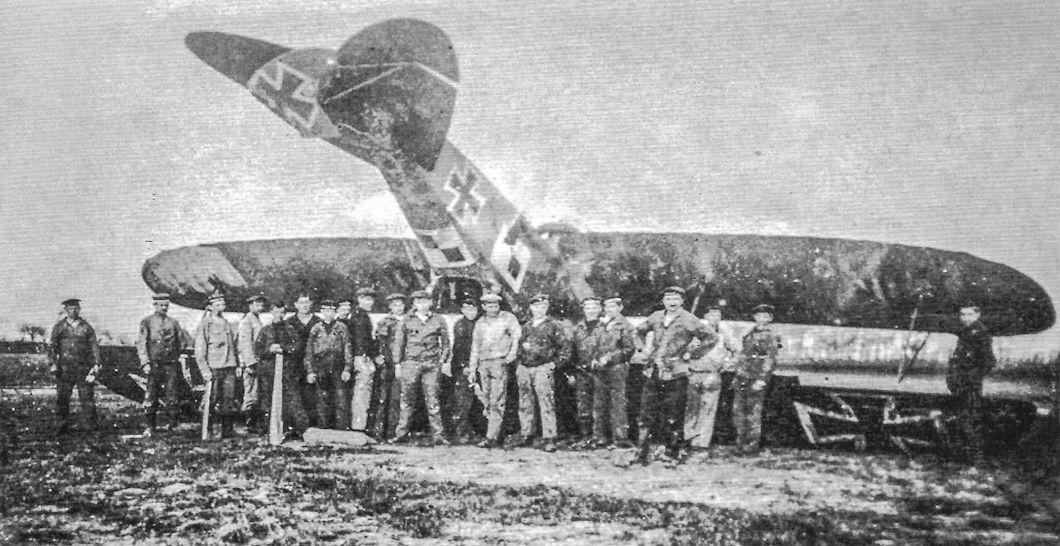
DFW C.V of a naval unit has come to grief. The checkerboard marking was applied to the top of the rear fuselage was well as to the fuselage sides.

Views of a late-production DFW C.V with leading-edge radiator and Totenkopf (death's head) fuselage insignia flown by Flieger-Abteilung (A) 199b. The aircraft after a bad landing showing the Totenkopf insignia was applied to both sides of the fuselage.

DFW C.V of Flieger-Abteilung 7 photographed in 1918; the fuselage insignia has been heavily overpainted with the new Balkenkreuz and the rudder insignia has also been overpainted with the new insignia.

DFW C.V(LVG) 5213/16 tactical '1' of Flieger-Abteilung (A) 211 after a rough landing. It is an early production aircraft with ear radiators. (Bruno Schmaling)

This DFW C.V of a naval unit has been wrecked in a bad landing. It carries an interesting large, open five-pointed star insignia. (Bruno Schmaling)

The DFW-built DFW C.V from FliegerAbteilung 2 shot down on the Italian front. This aircraft also wore the unusual streaky camouflage. Relics from this aeroplane are still in the Vittorio Veneto museum.

DFW C.V of Flieger-Abteilung (A) 282 with comet insignia and patched bullet holes in the tail. After returning from each flight to the front the crew painted another little star next to the comet.

DFW C.V of Uffz. Scholz and Lt. Lange with a horseshoe emblem after a bad landing.

Crashed DFW C.V of Flieger-Abteilung 68 showing an interesting marking. The standard vent in front of the vertical fin is clearly shown.


Rudolf Stark's painting of flying his DFW C.V 6022/17 in combat with several Spad fighters. In addition to being a fighter ace, Staffelfuhrer, and noted author, Stark was also an accomplished artist. This painting shows the colors of his C.V.

DFW C.V recognition chart.

Plan view of DFW C.V(LVG) of FliegerAbteilung 48. 1917.

DFW C.V C.3xxx/16 of Schusta 8, July 1917 at Mousay Aerodrome. The stylized "W" is the unit insignia.

DFW C.V C.799/17 tactical "7" of FliegerAbteilung 7 was brought down on 12 July 1917 by pilots of No.56 Sqdn, RFC.

Factory finish applied to Halberstadt-built C.V aircraft when fuselage was stained.

DFW C.V LVG-built Batch C.5040 - C.5289/16 Trial Camouflage Reconstruction (c) Piotr Mrozowski

DFW C.V Aviatik-built Batch C.100 - C.199/17 Trial Camouflage Reconstruction (c) Piotr Mrozowski

DFW-built C.V Batch C.750 - C.899/17 Trial Camouflage Reconstruction (c) Piotr Mrozowski

DFW C.V Halberstadt-built Batch C.2500 - C.2524/17 Trial Camouflage Reconstruction (c) Piotr Mrozowski

DFW C.V Halberstadt-built Batch C.3378 - C.3427/17 Trial Camouflage Reconstruction (c) Piotr Mrozowski

DFW-built C.V Batch C.4578 - C.4727/17 Trial Camouflage Reconstruction (c) Piotr Mrozowski

DFW-built C.V Batch C.7750 - C.7949/17 Trial Camouflage Reconstruction (c) Piotr Mrozowski

DFW C.V Aviatik-built Batch C.200 - C.349/18 Trial Camouflage Reconstruction (c) Piotr Mrozowski

DFW-built C.V Batch C.2300 - C.2449/18 Trial Camouflage Reconstruction (c) Piotr Mrozowski

DFW-built C.V Batch C.4400 - C.4499/18 Trial Camouflage Reconstruction (c) Piotr Mrozowski

DFW C.V

DFW C.V

DFW C.V

DFW C.V

DFW C.V
DFW R-Planes
In 1915 DFW joined the R-plane program at the request of Idflieg. DFW's R-plane designs were carefully engineered and featured good craftsmanship. The key contribution of the DFW designs was a simple, straightforward solution to drive the propellers from internally-mounted engines. The DFW R-planes were unique because they were the only R-plane designs that had internally-mounted engines each driving a separate propeller. This eliminated much of the weight and complexity of mechanisms designed to couple the engines together to drive all the propellers from any combination of engines. Instead of that complex system, each engine drove a transmission shaft and right-angle gearbox driving a separate propeller; simplifying the mechanical systems provided greater reliability.
DFW built one DFW R.I in 1916 that was subjected to extensive evaluation and modification. Six improved DFW R.II aircraft were ordered, of which three were completed in 1917-1918. Two more R.II aircraft were almost complete at the end of the war; Idflieg cancelled the sixth due to mediocre performance. Idflieg ordered two of the more powerful DFW R.III giants on 3 September 1918; design of the R.III was nearly complete by the Armistice but construction of these huge aircraft had not yet started.
DFW R.I
Design of the DFW R.I was by Hermann Dorner, who was the DFW lead engineer at the time; in October 1916 he left DFW to become chief engineer at Hannover, where he designed the very successful Hannover CL.II, CL.III, and CL.V two-seat fighters. Dorner was assisted by Heinrich Oelerich, a famous pre-war pilot who was DFW's chief pilot. After Dorner left for Hannover, Oelerich led development of the DFW R.II and R.III.
A key technical challenge for multi-engine aircraft of the time was that their fixed-pitch propellers could not be feathered in case of engine failure. The subsequent drag of a wind-milling propeller was comparable to that of a parachute of the same diameter, with the result that most multi-engine aircraft could not sustain level flight after an engine failure. This was clearly not acceptable for the large, costly, and fragile R-planes that were so susceptible to serious damage or destruction in the event of a forced landing.
To address this issue some R-plane designers included a complex drive assembly to enable a failed engine to be disconnected from the propellers and enabling all the propellers to be driven by the engines that were still running. This was theoretically an excellent solution; unfortunately, it had many practical pitfalls. In addition to the extra weight of these complex systems, their very complexity, combined with immature technology, resulted in serious reliability problems.
While retaining the engines internal to the aircraft where the flight engineers could perform repairs in flight, DFW, in contrast, designed each engine to drive a separate propeller via a gearbox, drive shaft, and clutch. The clutch enabled a failed engine to be disconnected from its propeller. While this enabled the propeller of a failed engine to wind-mill, it also reduced the weight and complexity of the design and contributed to greater reliability.
The DFW R.I was powered by four 220 hp Mercedes D.IV straight-eight engines, among the most powerful engines available at the time the R.I was designed. The forward pair of engines each drove one of the forward propellers, which were mounted in tractor configuration just below the upper wing. The aft pair of engines were mounted lower and each drove one of the aft propellers, which were mounted as pushers just above the lower wing. Despite the basic simplicity of the design many months of refinement were still required to achieve the desired reliability.
Initially the engines were cooled by triangular radiators between the center section struts. However, these were soon replaced by four Windhoff radiators positioned on the fuselage within the center section gap for improved cooling. These had adjustable shutters and were similar to the radiators used on early production DFW C.V aircraft.
The R.I was built with three-bay wooden wings of wood, wire, and fabric construction that were typical except for their size. The fuselage was also wood although the engines were mounted in a pressed steel framework that was integrated into the fuselage structure. The R.I initially had two rudders without a fixed fin. Flight testing soon revealed that was inadequate and the R.I was modified for better stability and controllability by adding a fixed fin and enlarging the rudders.
The R.I was equipped to carry three machine guns and the hump on the upper fuselage behind the wings was to give the rear upper gunner a better field of fire.
First flight of the DFW R.I was on 5 September 1916. The R.I was delivered to the Army air park at Boberitz after 12 factory flights of eight hours duration, where it successfully completed its 2 1/2 acceptance flight on 19 October. A number of crankshaft failures occurred during additional flights due to the long crankshaft of the straight-eight engines. The engine mounts had to be greatly reinforced to reduce engine vibrations for greater reliability. The span was also enlarged slightly which required an additional bracing strut between the wing tips.
On April 30, 1917 the R.I was flown to Alt-Auz via Konigsberg to join Rfa 500. Evaluation there showed the DFW R.I could fly on two engines if its speed was maintained. Three engine flight required use of the rudders to balance the asymmetric thrust. The R.I was then returned to DFW for repairs before it returned to Rfa 500 in May.
The only combat mission of the R.I was flown by a crew of five on 13 June 1917 when it dropped 680 kg on a Russian target. After mechanical delays, the R.I attempted a second bombing attack in September 1917. One of its engines failed while flying to the target and the aircraft commander decided to return to base. A second engine had to be stopped during the return flight due to a gearbox severely over-heating. Altitude could not be maintained with two engines and a full bomb load, and an emergency landing was attempted at a nearby airfield. A good landing was made but the R.I ran into a trench that had not been visible; it broke up and burned, causing the bombs to explode. The R.I was destroyed and one crewman was killed.
DFW R.II
After prolonged flight evaluation of the DFW R.I Idflieg determined that it had adequate performance and flying characteristics, and on 13 November 1916 ordered six improved R.II aircraft that were more powerful developments of the R.I. In particular, the R.II had the more powerful and more reliable 260 hp Mercedes D.IVa six-cylinder engine. In addition to slightly greater power, the shorter crankshaft of the six-cylinder D.IVa made it significantly less susceptible to vibration than the long, straight-eight-cylinder D.IV engine.
The R.II was larger and heavier than the R.I with considerably more wing area. Like the R.I the R.II used four engines and had a very similar configuration and structure. The engines and drive train were mounted in pressed steel mounts that also braced the fuselage, wings, fuel tanks, bomb bay, landing gear, and center-section struts for a robust airframe. Again the engines drove separate propellers through drive shafts and bevel gears. The wooden fuselage had internal bulkheads and was braced by steel frames and cables. The fuselage was covered in plywood and the floors and catwalks were an integral part of the structure. All this attention to structural strength resulted in a robust fuselage.
The three-bay wings were built of wood like the R.I and braced internally with steel tubes and cables. The interplane struts were made of steel tubes and faired to minimize drag. Again like the R.I, the ailerons were fitted to the upper wing only. The biplane tail was modeled on the final tail configuration of the R.I. The R.II had three flexible machine guns positioned similarly to those of the R.I.
The first R.II, R.15/16, made its maiden flight on 17 September 1917. Serious vibrations marred an otherwise successful flight. The problem was due to the high rotational speed of the outrigger transmission shafts, a problem that was resolved by encasing the shafts by stiffener tubes.
Sabersky-Mussigbrodt returned to DFW from LFG in March 1918 as the chief engineer of DFW's R-plane section. The R.15 was delivered to the Riesenflugzeugersatsabteilung (R-plane Support Section) in Cologne on 1 April 1918. By this time the Zeppelin-Staaken types had surpassed the DFW R.II in performance, reliability, and payload due to the prolonged development of the DFW R-planes. The result is that not one DFW R.II saw operational service; instead they were used for training aircrews and experimental work. Later in 1918 the R.15 suffered a serious crash and Oelerich was crippled for life due to his injuries.
R.II R.16/16 was completed in February 1918. The second DFW R.II, it had disappointing performance. Modifications were recommended in April and some were implemented. In any case, Idflieg determined that the R.16/16 would have to offer satisfactory results before the other four DFW R.II aircraft were completed.
The most important modification was installation of a Brown-Boveri supercharger driven by a 120 hp Mercedes D.II engine installed specifically for the purpose. On 21 May the R.16/16 was flown from DFW to Grosszschocher for the installation. Ground tests were completed without problems and on 22 July 1918 the first test flight was undertaken. In addition to the supercharger system a third rudder on the central fixed fin was installed to improve maneuverability. The serial of R.16/16 was also changed to R.16/17 to reflect the new accounting. The modified R.16/17 was ready for operational service in October 1918, just before the Armistice.
By this time three of the six R.II aircraft ordered were complete and R.18 and R.19 were nearly complete. R.20 was cancelled due to mediocre performance. Post-war DFW received funds to complete R.18 and R.19 as passenger aircraft, but instead the aircraft were scrapped.
DFW R.III
The DFW R.III was a larger, more powerful development of the R.II to overcome the mediocre performance of the R.II. The basic problem with the R.II was the need for more power, and the R.III design addressed that with the use of eight 260 hp Mercedes D.IVa engines instead of the six engines in the R.II. Each of the eight engines drove a separate propeller arranged in four counter-rotating pairs, two in front and two behind the wing.
Other than the additional, counter-rotating propellers, the R.III construction and configuration were similar to the R.II, although the R.III had a fourth machine gun position for defense. Bomb load was increased to a planned 2,500 kg. One or two 120 hp Mercedes D.II engines driving superchargers were expected to maintain performance up to 5,000 meters.
Idflieg ordered two examples of the new R.III design on 3 September 1918. An interesting feature included at Idflieg’s request was a navigator's steering station in front of the wings. The navigator had only minor steering authority, but his small corrections were expected to be useful for landing and bombing. The latter was a beneficial feature incorporated into future bombing systems, but the former was not practical.
The R.III was to have a monoplane tail mounted atop the rudder and a tail wheel instead of a skid.
The R.III design, which was under the direction of Dipl.-Ing. Willy Sabersky-Mussigbrodt, was approaching completion at the Armistice, but construction had not started.
DFW R-Plane Specifications
DFW R.I DFW R.II DFW R.III (Project)
Engine 4 x 220 hp Mercedes D.IV 4 x 260 hp Mercedes D.IVa 8 x 260 hp Mercedes D.IVa + 1 or 2 120 hp Mercedes D.II engines to drive superchargers
Span, Upper 29.5 m (30.5 m - 2nd vers.) 35.06 m 53.5 m
Chord, Upper - 4.4 m 6.4 m
Gap - 4.19 m 6.5 m fuselage/5.75 m wing
Wing Area 182 m2 (186 m2 - 2nd vers.) 266 m2 -
Length 17.6 m 20.93 m 25 m
Height 6.0 m 6.4 m 8.6 m
Empty Weight 5,652 kg (6,800 kg 2nd vers.) 8,634 kg 639 kg
Loaded Weight 8,380 kg (9,400 kg 2nd vers.) 11,693 kg 819 kg
Maximum Speed 120 km/h 135 km/h 177 km/h (estimated)
Climb to 1,000m 10 minutes - -
Climb to 2,000m 25 minutes 58 minutes -
Climb to 3,300m 53 minutes - -
Armament 3 guns & 680 kg of bombs 3 guns & bombs 4 guns &. 2,500 kg of bombs
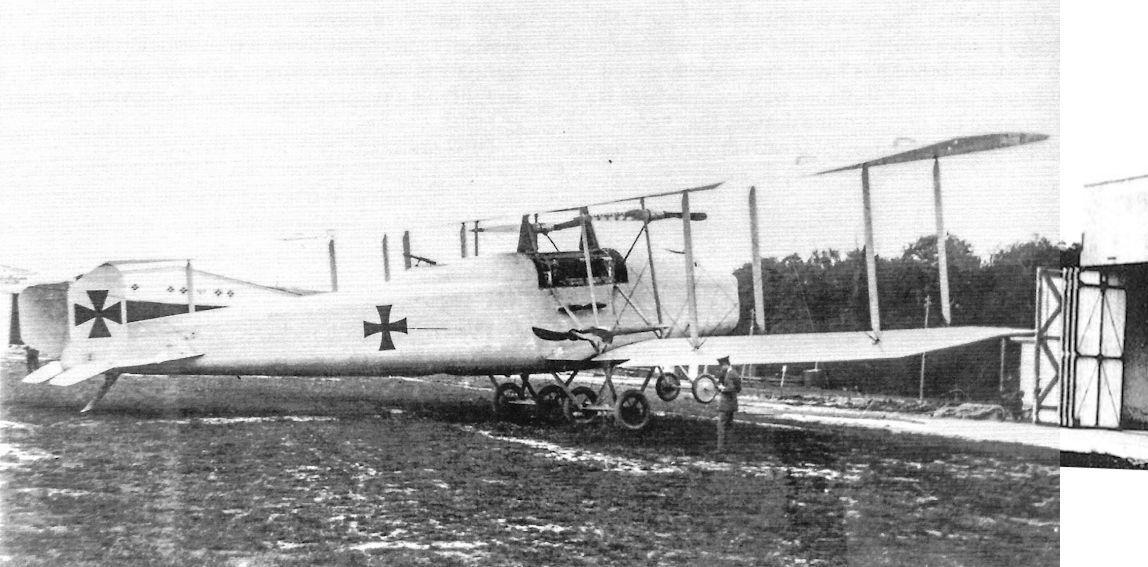
The DFW R.I 11/15 in 1916 in its original form without supplementary wing-tip struts, and fitted with triangular radiators.
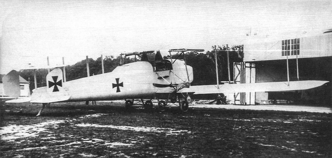
The DFW R.I, serial R.11/15, shown in its initial configuration in 1916. (Peter M. Grosz Collection/SDTB)
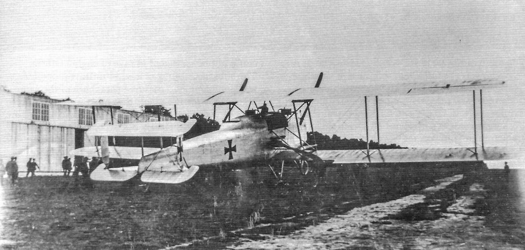
The DFW R.I, serial R.11/15, shown in its initial configuration in 1916. (Peter M. Grosz Collection/SDTB)
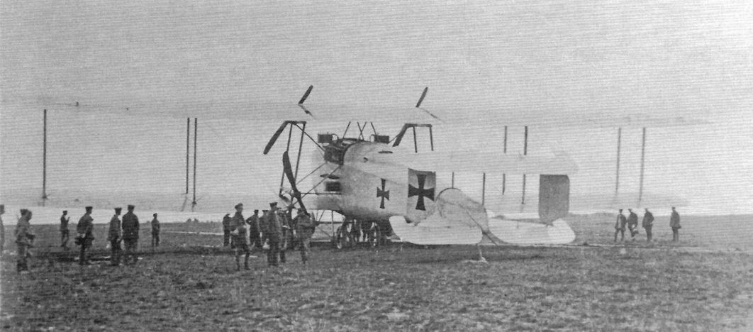
The DFW R.I, serial R.11/15, shown in its initial configuration in 1916. At this time the R.I was painted a light color overall with national insignia applied directly over the finish. (Peter M. Grosz Collection/SDTB)
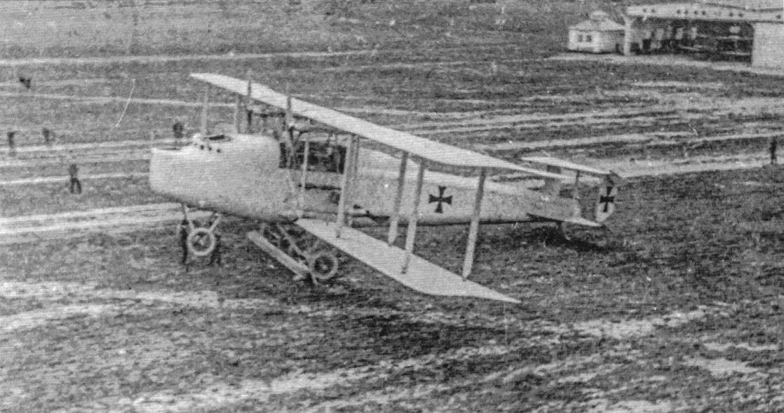
The first R-plane built by DFW was the R.I, serial R.11/15, in 1916. It is shown here in its initial configuration.
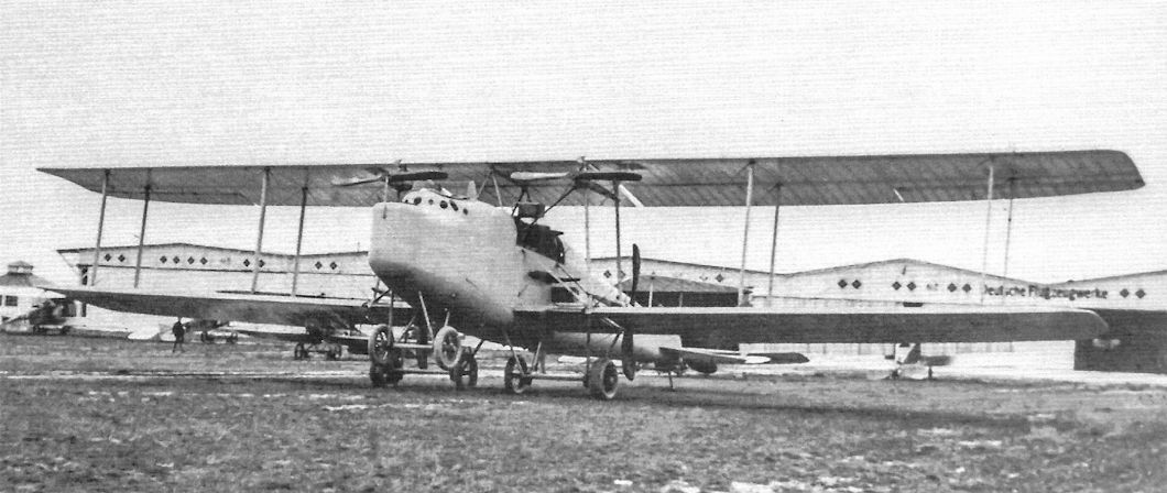
The DFW R.I, serial R.11/15, shown in its initial configuration in 1916. (Peter M. Grosz Collection/SDTB)
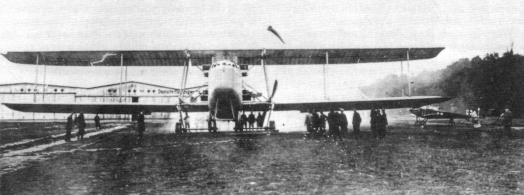
The DFW R.I, serial R.11/15, shown in its initial configuration in 1916. (Peter M. Grosz Collection/SDTB)
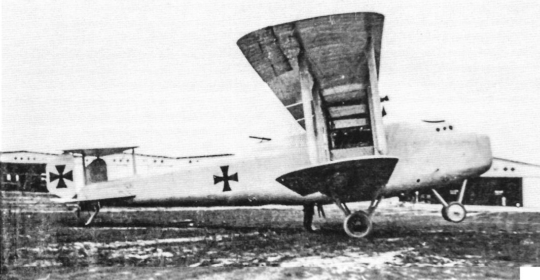
The DFW R.I, serial R.11/15, shown in its initial configuration in 1916. Its factory designation was T 26. This photograph shows the first form of the tail unit with no fixed vertical surfaces.
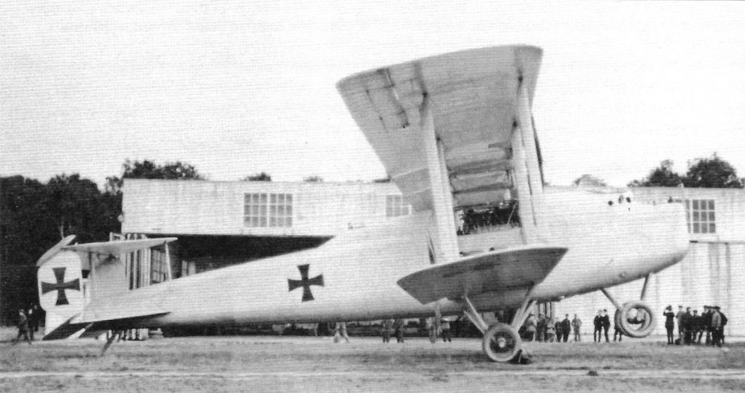
The DFW R.I, serial R.11/15, shown in its initial configuration in 1916. The radiators can be seen in the center section between the center section struts. (Peter M. Grosz Collection/SDTB)
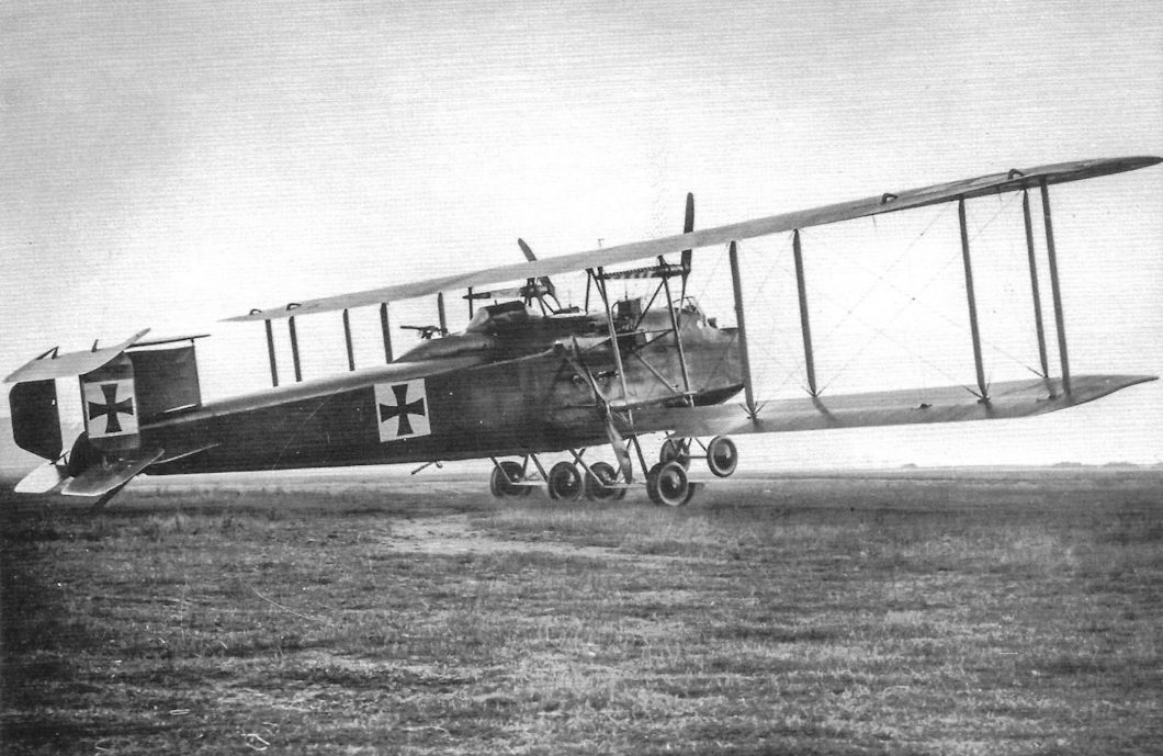
The DFW R.I shown in its final configuration. In its first configuration the R.I had been painted a light color overall with national insignia applied directly over the light finish. After conversion to its final configuration the R.I was painted a dark camouflage on its upper surfaces and a light color, possibly light blue but more likely yellowish white, underneath. The national insignia were now applied over white fields. (Peter M. Grosz Collection/SDTB)
Note ventral machine-gun and large gravity fuel tank not fitted to the early version.
Note ventral machine-gun and large gravity fuel tank not fitted to the early version.
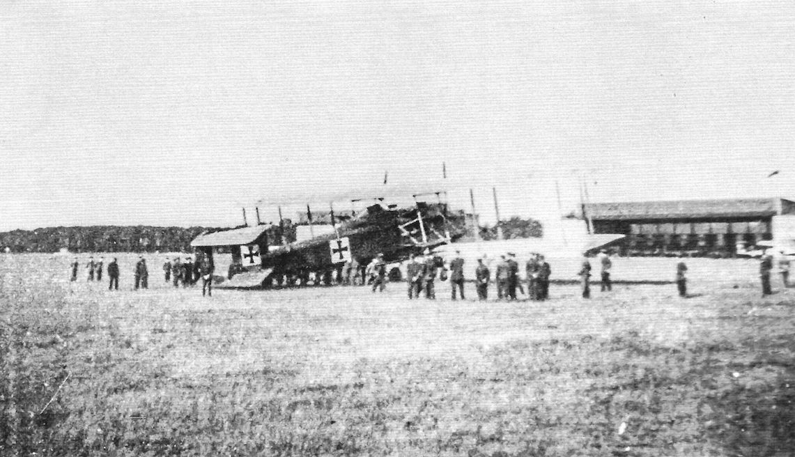
The DFW R.I in its final configuration is surrounded by admirers on the DFW factory airfield.
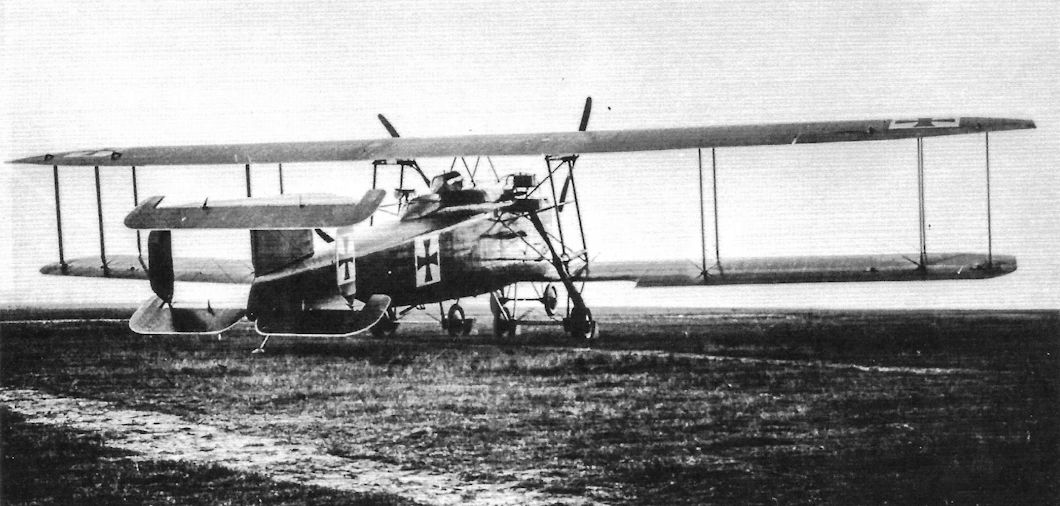
The DFW R.I in its final configuration with fixed rudder and larger rudders. (Peter M. Grosz Collection/SDTB)
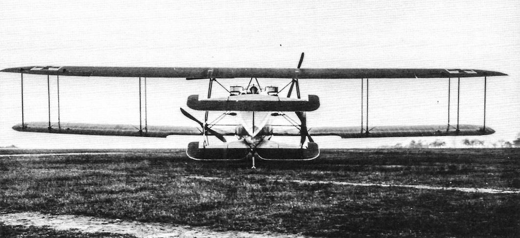
The DFW R.I in its final configuration with slightly greater wing span and additional struts near the wingtips. (Peter M. Grosz Collection/SDTB)
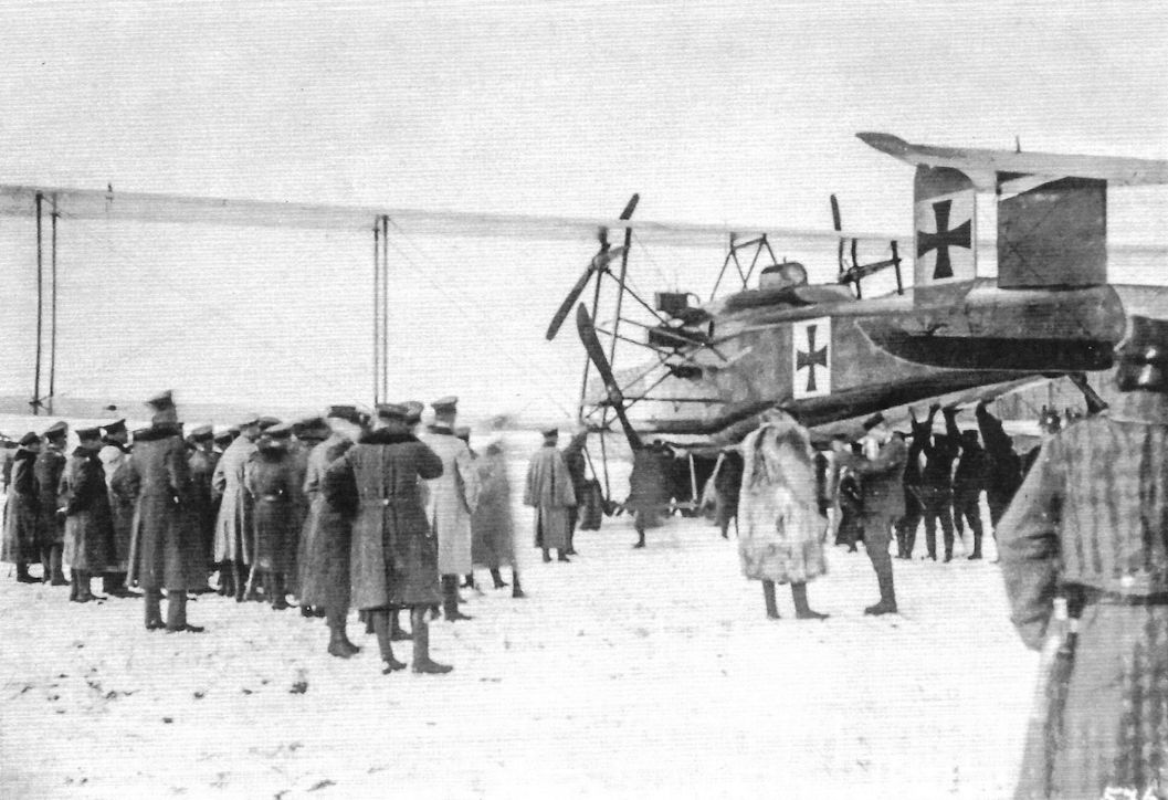
The DFW R.I in its final configuration is inspected by a large group despite the snow. (Peter M. Grosz Collection/ SDTB)
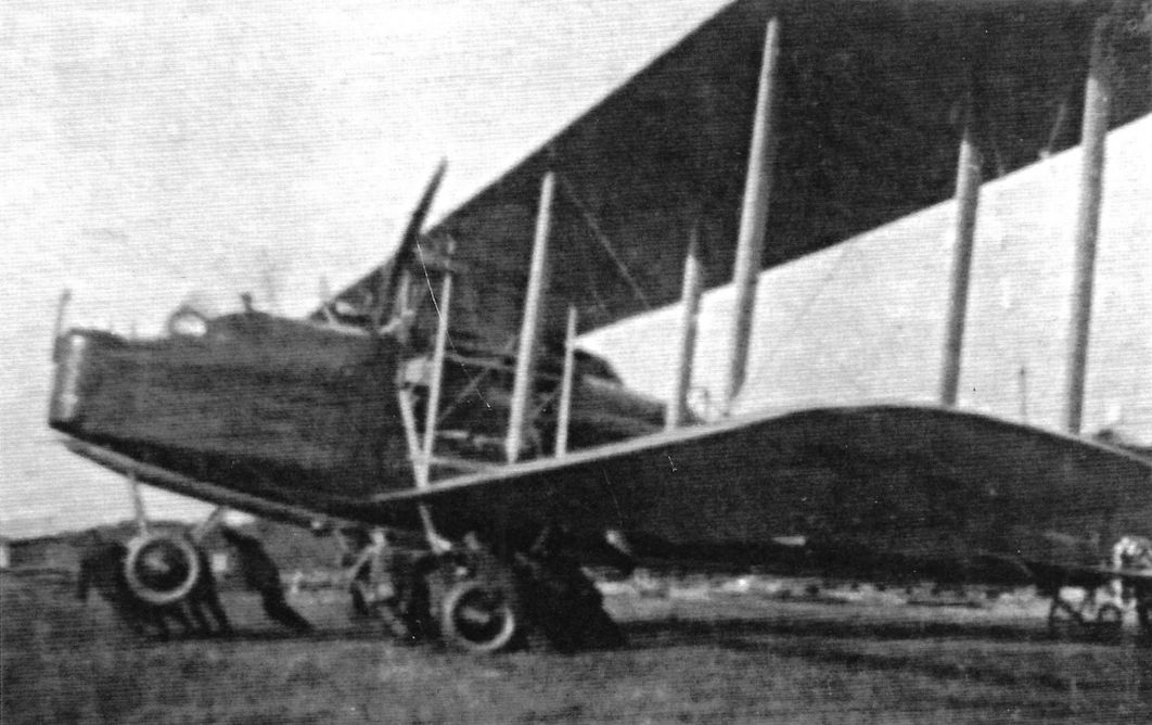
A ground crew struggles to move the DFW Rd. This is its final configuration.
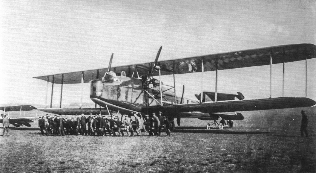
A large team of mean move the pristine DFW R.I in its final configuration. (Peter M. Grosz Collection/SDTB)
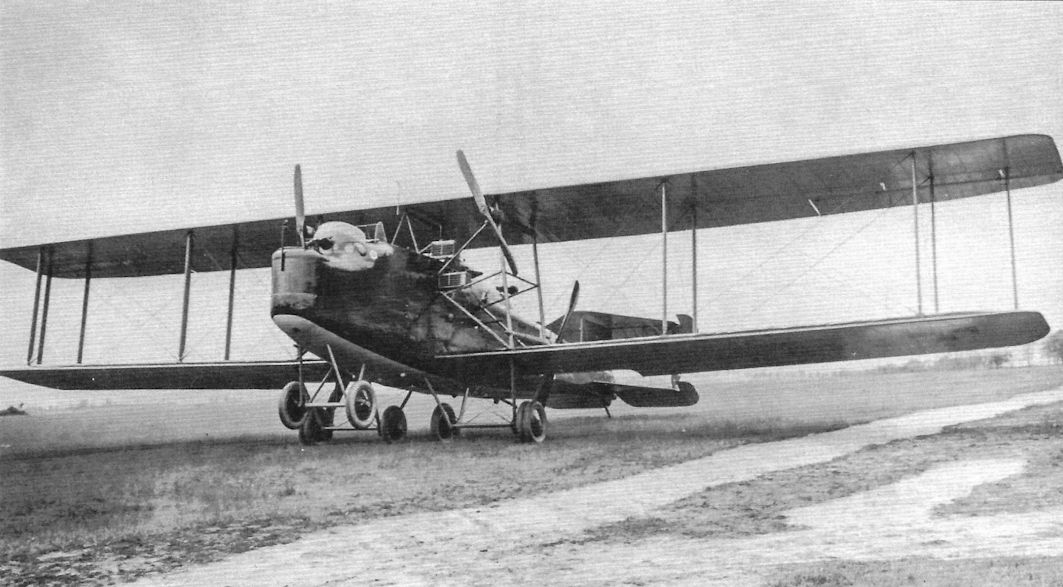
The DFW R.I in its final configuration with fixed rudder, larger rudders, and slightly lengthened wing span with additional struts at the wing tips. (Peter M. Grosz Collection/SDTB)
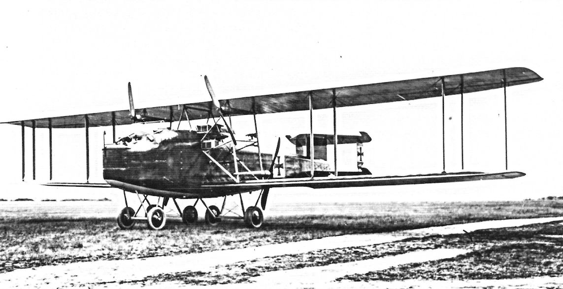
The DFW R.I in its final configuration.

The three gun positions in the DFW R.I are clearly shown in this view. (Peter M. Grosz Collection/SDTB)
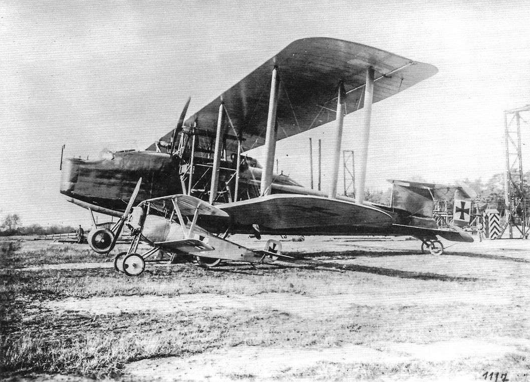
The DFW R.I 11/15 in its final form. The machine in the foreground is a SSW D.1 fighter.
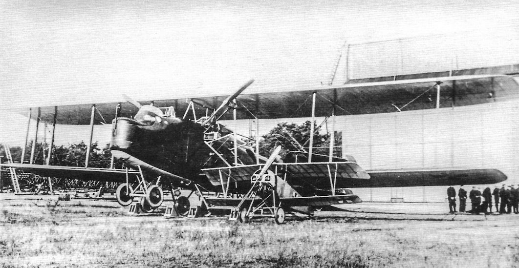
The DFW R.I is its final configuration is joined by an SSW D.I fighter to provide a size comparison. The R.I has full camouflage paint and all the other upgrades. The massive DFW R.I was a 'canvas overcast'. (Peter M. Grosz Collection/SDTB)
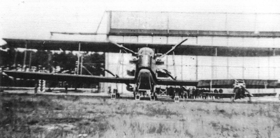
The DFW R.I in its final configuration with fixed rudder and larger rudders. An SSW D.I is parked in front of the R.I to provide a size comparison.
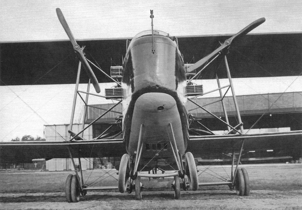
This impressive front view of the DFW R.I in its final configuration illustrate its massive size and attention to drag reduction. (Peter M. Grosz Collection/SDTB)
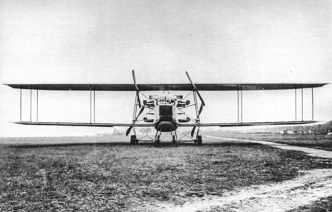
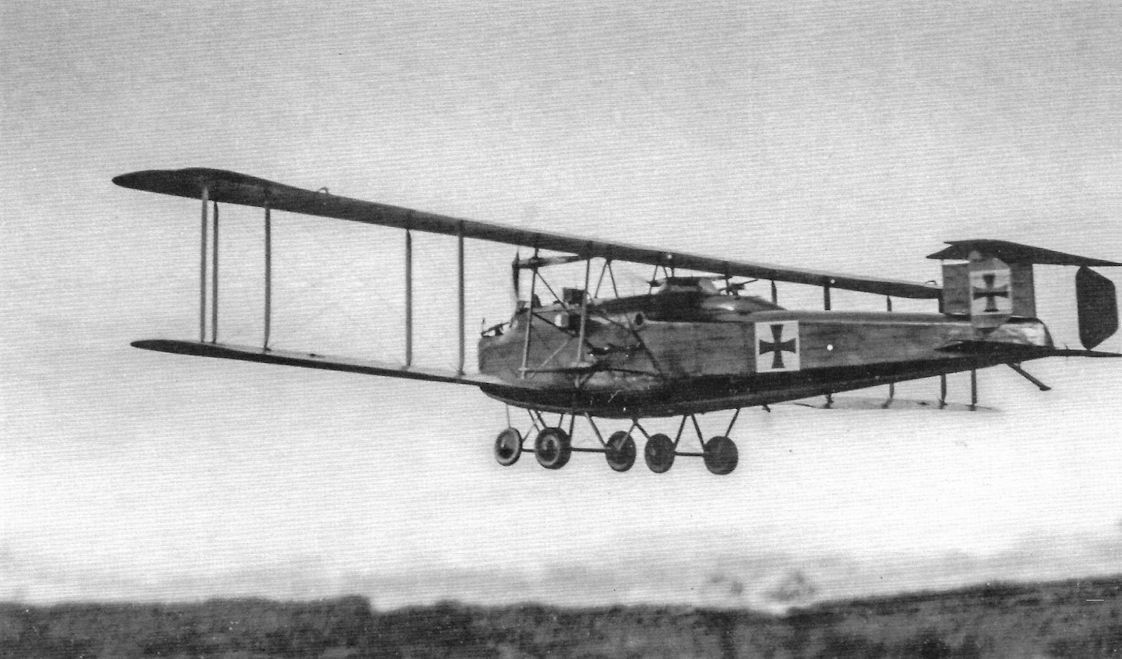
A dramatic image of the imposing DFW R.I in flight. (Peter M. Grosz Collection/SDTB)
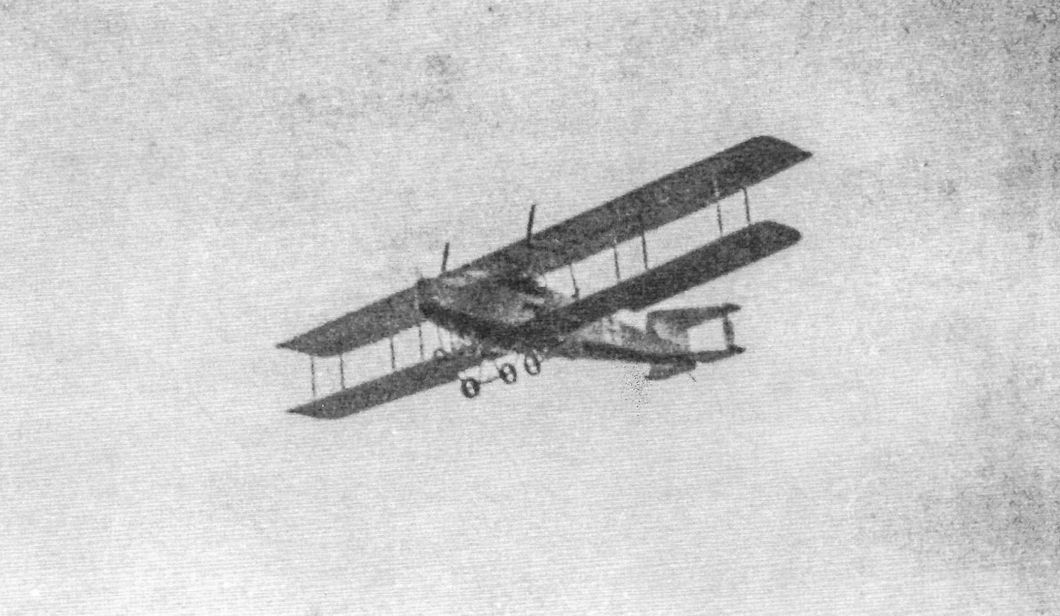
The DFW R.I in an intermediate configuration after being painted. (Peter M. Grosz Collection/SDTB)
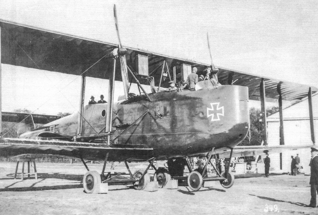
Closeup of DFW R.II R.15/16. Its factory designation was T 26-II. (Peter M. Grosz Collection/SDTB)
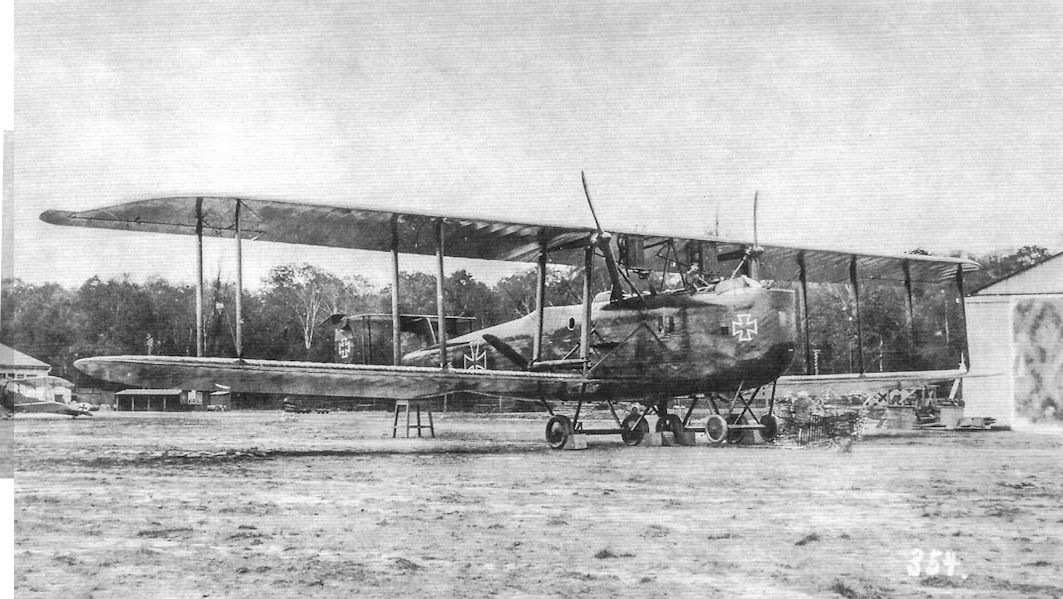
Full view of DFW R.II R.15/16 after aerodynamic horn balances were added to the ailerons for better handling
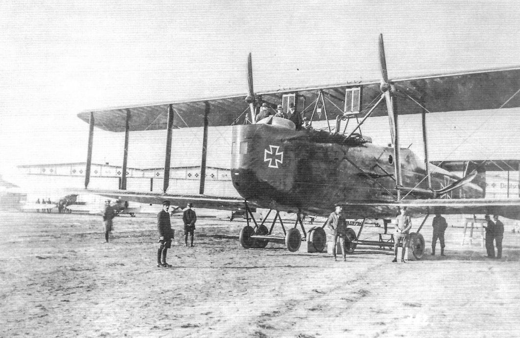
View of the first DFW R.II, R.15/16, at the DFW factory. The view shows the initial configuration. (Peter M. Grosz Collection/SDTB)
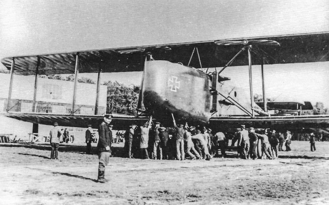
Views of the first DFW R.II, R.15/16, at the DFW factory; the aileron horn balances are clearly visible. These reduced control forces and made the ailerons more responsive. (Peter M. Grosz Collection/SDTB)

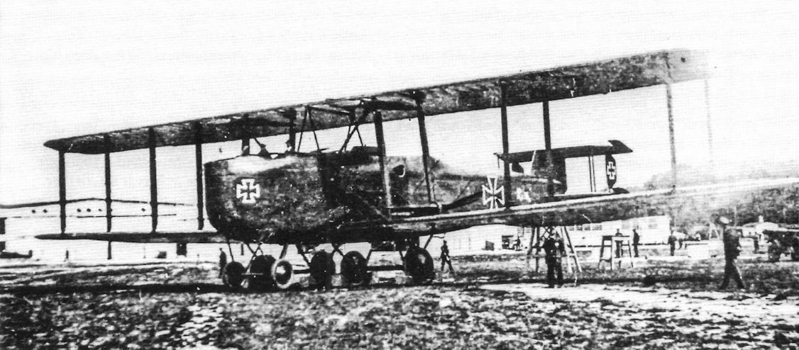
DFW R.II R.15/16, the first DFW R.II, at the DFW factory. Although bulky and hardly elegant, the DFW R-planes were carefully designed to minimize drag.Their protracted development meant they were surpassed in all respects by the Zeppelin-Staaken R-planes. With only a single bombing mission to their credit, the DFW R-planes consumed priceless engineering and production resources without making any impact on the air war. (Peter M. Grosz Collection/SDTB)
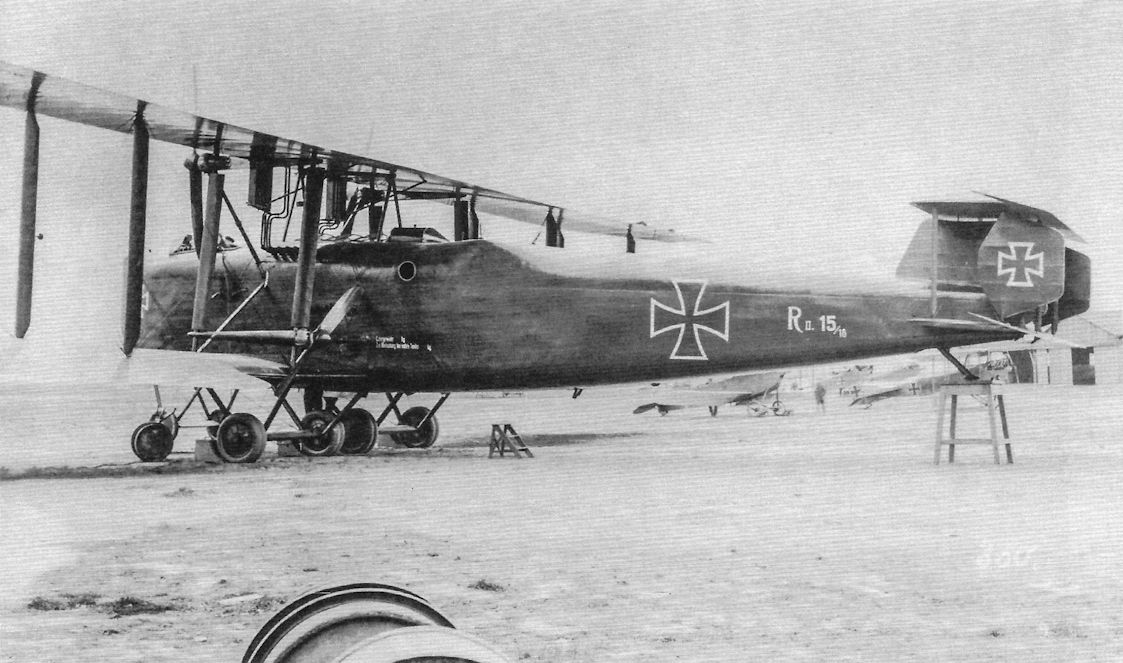
Side view of DFW R.II R.15/16. (Peter M. Bowers Collection/Museum of Flight)
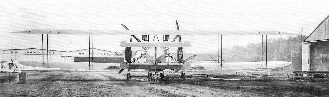
Rearview of DFW R.II R.15/16 in front of the DFW company hangars; the ailerons have horn balances.
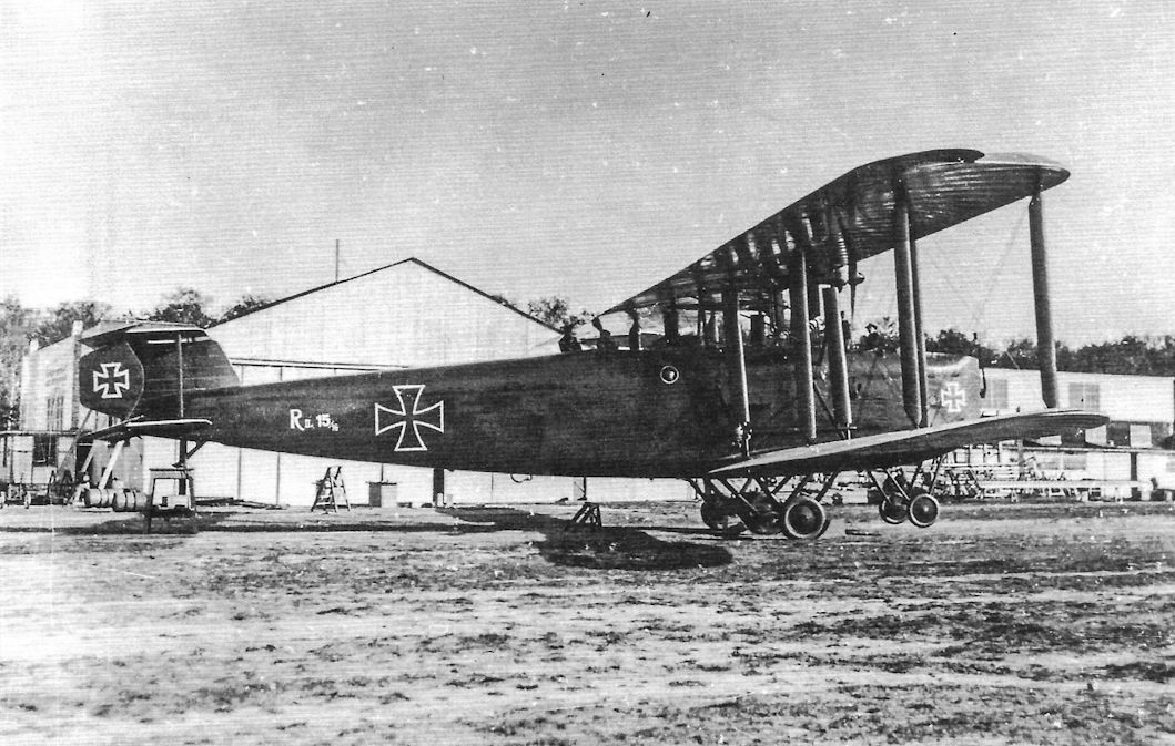
DFW R.II R.15/16, the first DFW R.ll, at the DFW factory. (Peter M. Grosz Collection/SDTB)
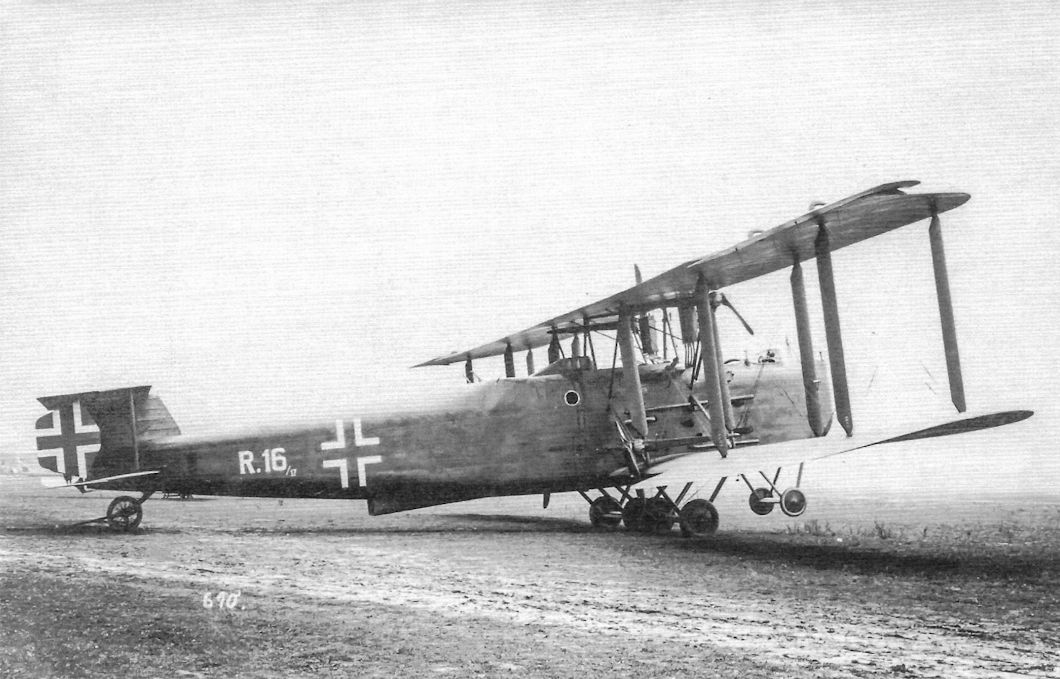
Full view of DFW R.II R.16/17 after the supercharger system was installed. A ramp has now been installed for the ventral machine gun position and the national insignia are now the 1918 style. (Peter M. Grosz Collection/SDTB)
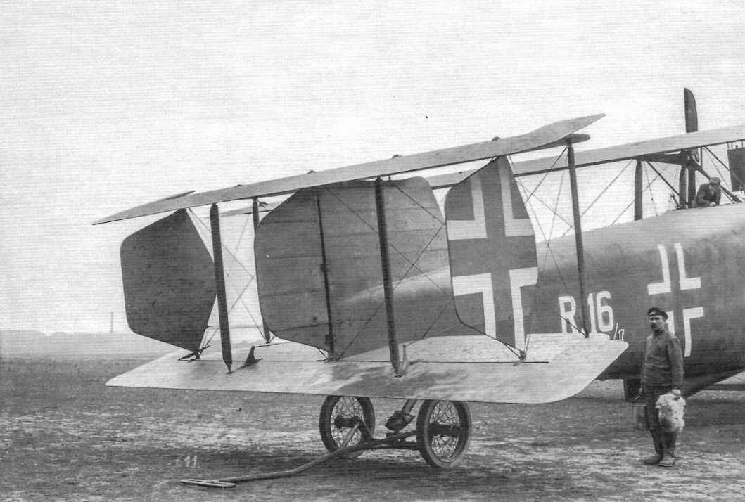
Closeup of the tail of DFW R.II R.16/17 after the third rudder was added. (Peter M. Grosz Collection/SDTB)
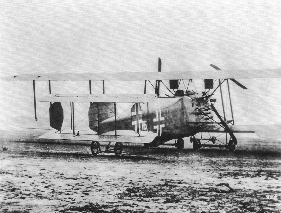
The DFW R.II R.16/17 after addition of all modifications. (Peter M. Bowers Collection/Museum of Flight)
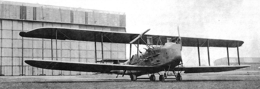
The R.II was the second R-plane design by DFW. R.II serial R.16/17 shown here was supercharged; the ducts for the pressurized air for the engines are visible on the outside of the fuselage.
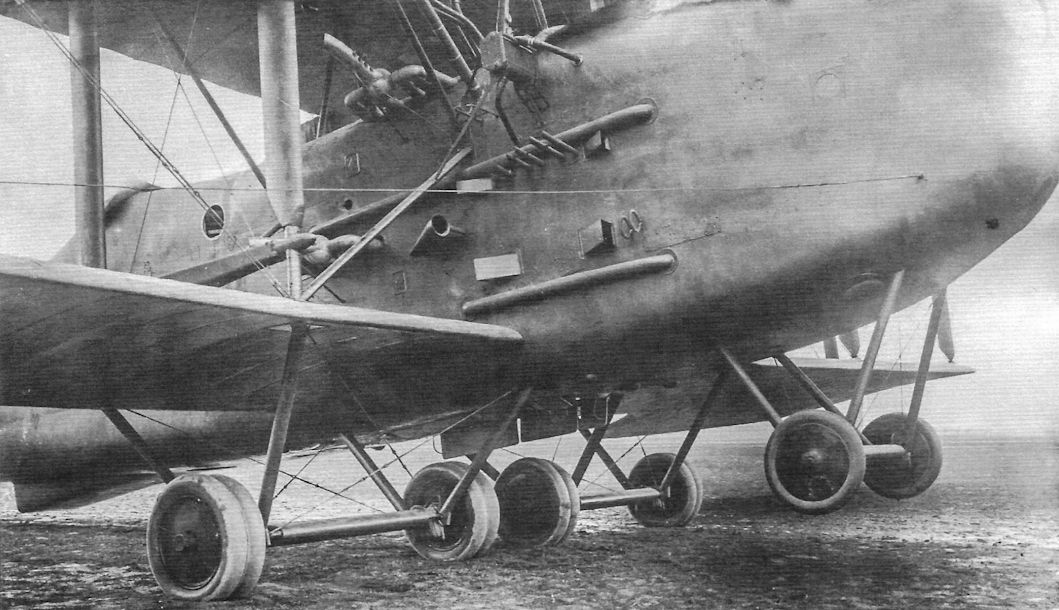
The second DFW R.II, R.16/17, at the DFW factory after the supercharger system was installed in July 1918. (Peter M. Grosz Collection/SDTB)
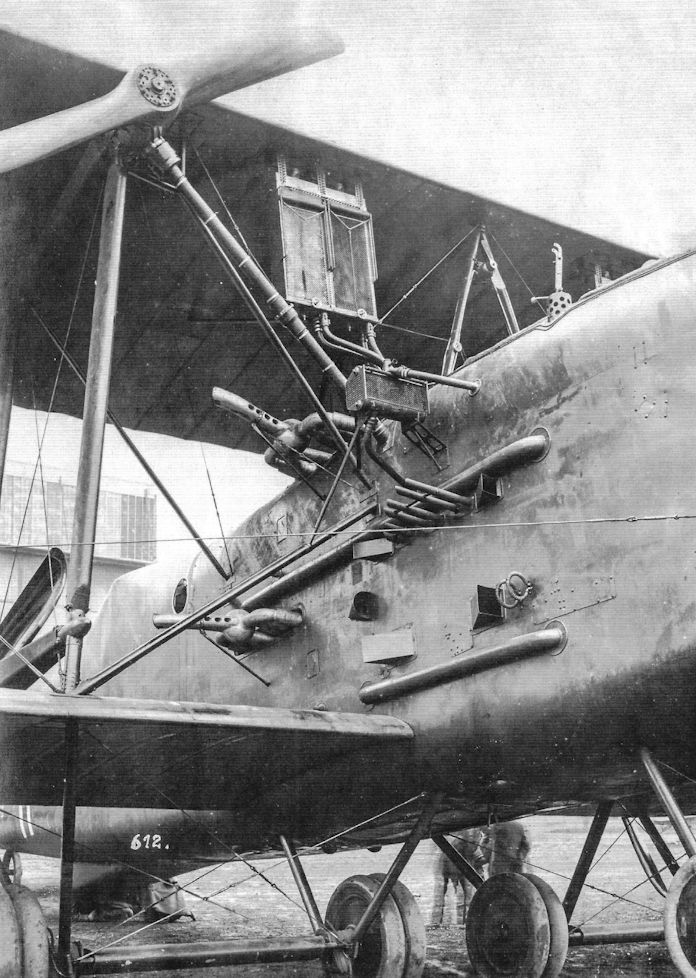
The second DFW R.II after the supercharger system was installed in July 1918. The external ducts for pressurized air are visible along with radiator and exhaust details. (Peter M. Grosz Collection/SDTB)
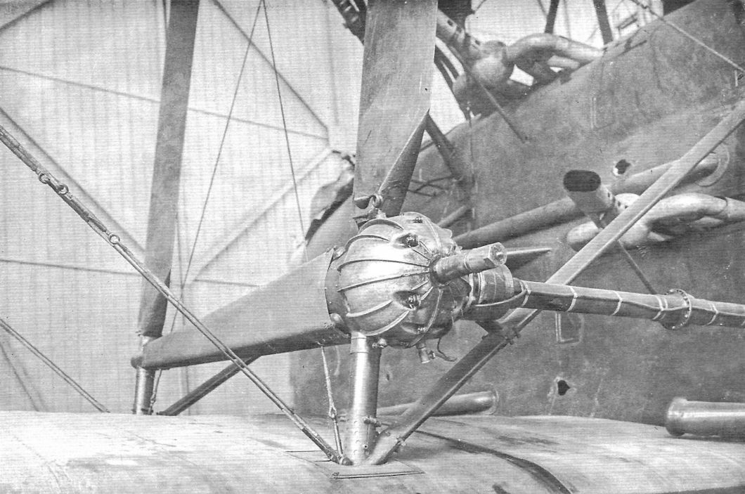
Closeup of the port aft driveshaft and gears for the pusher propeller on the second DFW R.II, R.16/17. (Peter M. Grosz Collection/SDTB)
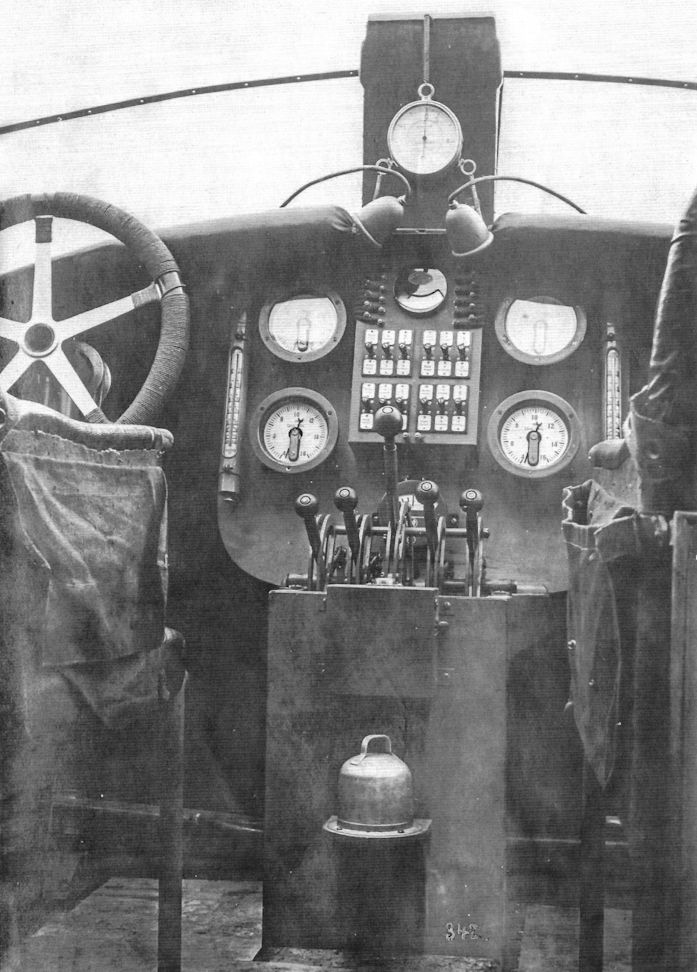
Cockpit of DFW R.II R.16/17; the instrument panel has four tachometers, two water thermometers, an electro plug box, altimeter, two dashboard lamps, and throttles. (Peter M. Grosz Collection/SDTB)
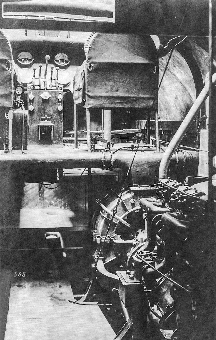
Flight deck of DFW R.II R.16/17 after the supercharger system was installed. (Peter M. Grosz Collection/SDTB)
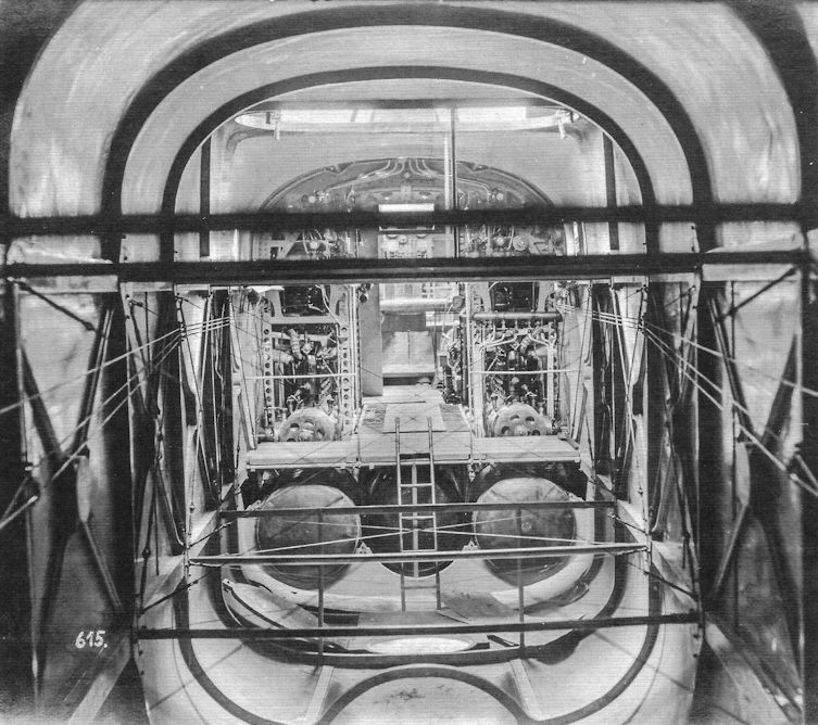
DFW R.II R.16/17 interior; it was painted a light color, probably ivory. (Peter M. Grosz Collection/SDTB)
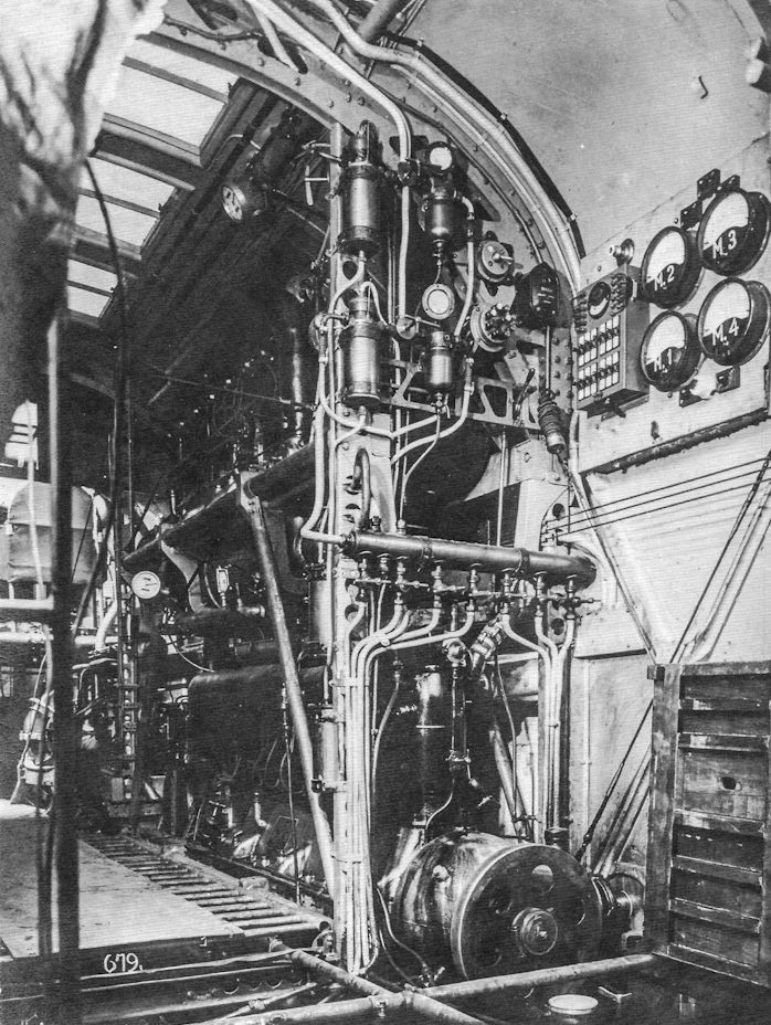
DFW R.II R.16/17 engine bay (left) and fuel control station, with gear boxes under the fuel valves. The thermometers for the various engines (M1, M2, M3, M4) are at right. (Peter M. Grosz Collection/SDTB)
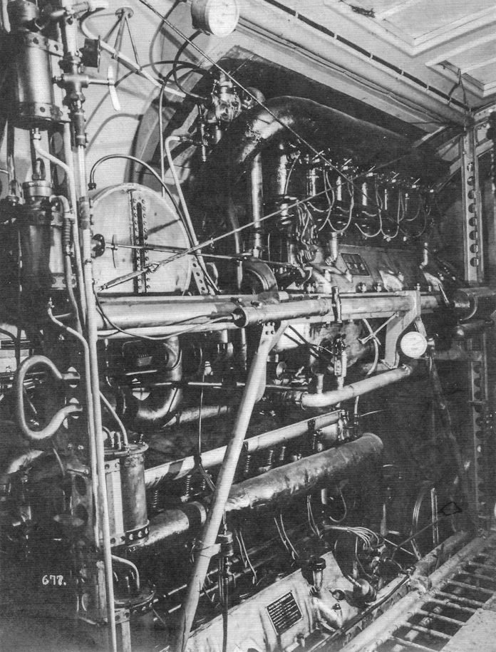
Port side of DFW R.II R.16/17 central engine bay. (Peter M. Grosz Collection/SDTB)
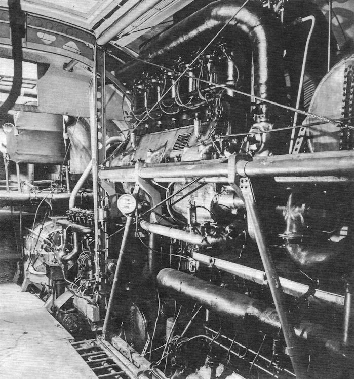
Starboard side of DFW R.II R.16/17 central engine bay. (Peter M. Grosz Collection/SDTB)
DFW C.VI
DFW clearly wanted to follow the great success of their C.V with an improved design, and the C.VI was their next attempt. The C.VI used the slightly more powerful 220 hp Benz Bz.IVa for enhanced performance. To improve maneuverability, horn-balanced control surfaces were fitted which reduced the pilot's control forces to improve responsiveness, and the rudder and fin were enlarged.
Apparently the C.VI offered insufficient improvement over the successful C.V that was already in large-scale production and only a single prototype is thought to have been built and evaluated.
DFW C-Type Specifications
DFW C.IV DFW C.V DFW C.VI DFW C.VII
Engine 150 hp Benz Bz.III 200 hp Benz Bz.IV 220 hp Benz Bz.IVa 220 hp Benz Bz.IVa
Span, Upper 13.30 m 13.27 m 13.60 m 13.60 m
Span, Lower - 12.80 m - -
Chord, Upper - 1.75 m - -
Chord, Lower - 1.75 m - -
Gap - 1.80 m - -
Wing Area 42.2 m2 41.52 m2 - 38.0 m2
Length 7.90 m 7.88 m 7.50 m 7.0 m
Height 3.3 m 3.26 m - 2.8 m
Empty Weight 720 kg 1,027 kg - 800 kg
Loaded Weight 1,230 kg 1,477 kg - 1,230 kg
Maximum Speed 135 km/h 155 km/h - 160 km/h
Climb to 1,000m - 4.0 minutes - 3.0 minutes
Climb to 2,000m - 7.0 minutes - -
Climb to 3,000m - 15.0 minutes - -
Climb to 4,000m - 25.0 minutes - -
Climb to 5,000m - 40.0 minutes - -
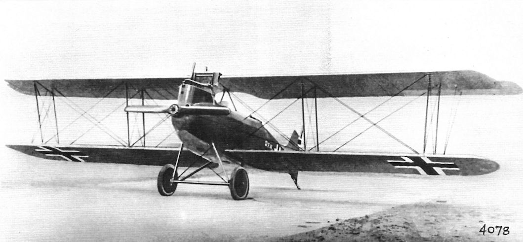
The DFW C.VI was powered by a 220 hp Benz Bz.IVa.The control surfaces were horn-balanced to reduce control forces and improve maneuverability. It is thought only the single prototype was built.
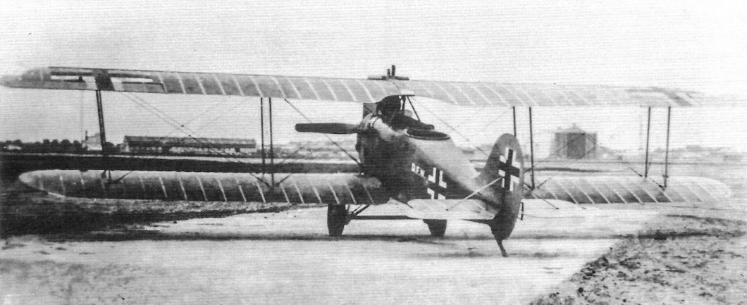
D.F.W. C VI
DFW D.I
Following the bizarre "Flea" DFW next designed the conventional T 34 fighter in both biplane (T 34-I) and triplane (T 34-II) forms and entered them in the First Fighter Competition. These two fighter prototypes shared everything but the wing cellule.
Both T 34 designs were powered by a 160 hp Mercedes D.III engine and were armed with two machine-guns. Photographic evidence shows that the biplane fighter was evaluated in at least three different configurations in a quest to improve maneuverability and handling qualities.
Both the biplane and triplane were submitted to the First Fighter Competition but were excluded from flight testing due to poor field of view for the pilot. No performance or dimensional data is available.
DFW D.II
Despite its earlier failures with the bizarre "Flea", disappointing T 34-I biplane, and the overly bestrutted T 34-II triplane, DFW persevered with fighter development and the clean, conventional DFW D.II, powered by a 170 hp Mercedes D.IIIa engine, was entered in the Second Fighter Competition. Again the DFW entry was rejected "for any front-line use" before flight evaluations began and again the type did not appear in the subsequent tables of data.
However, the D.II was rebuilt in July and was promising enough that it underwent the full set of static load tests. Unfortunately, the tests revealed structural weaknesses in the fuselage and tail and D.II development was terminated. It could not have helped that it was slower than the DFW "Flea".
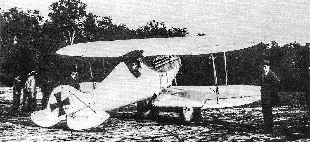
The first version of the DFW D.I fighter had a low, rounded vertical tail and ailerons on all wings connected by an actuating strut.
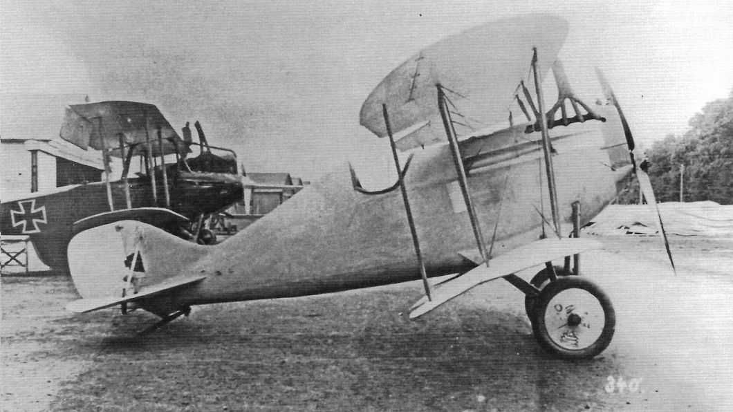
The second version of the DFW D.I fighter had a larger rudder and ailerons on all wings connected by an actuating strut. (Peter M. Grosz Collection/SDTB)
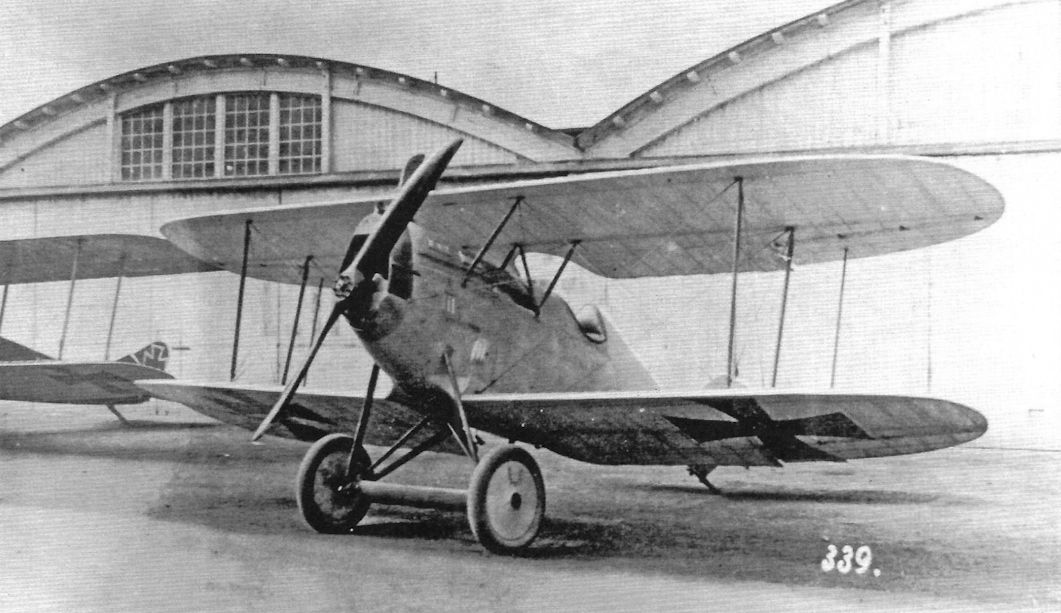
Front quarter view of the second version of the DFW D.I fighter with ailerons on all wings connected by an actuating strut. (Peter M. Grosz Collection/SDTB)
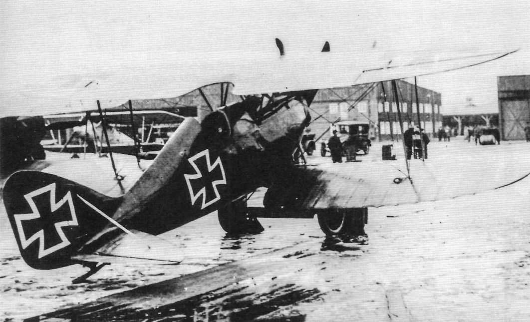
The third and final version of the DFW D.I seen here at the First Fighter Competition had a still larger fin and rudder and ailerons on the upper wings only.

Rear quarter view of the third version of the DFW D.I fighter with ailerons on the upper wings only; this version appears identical to the aircraft entered in the First Fighter Competition. (Peter M. Grosz Collection/SDTB)
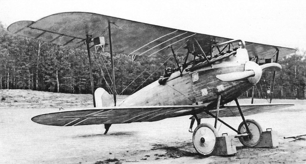
The DFW D.II (internal factory designation F 34), powered by a Mercedes D.IIIa, was entered in the Second Fighter Competition. Like the T 34 prototypes it was rejected before the flight evaluations began, but the reasons are not known. (Peter M. Grosz Collection/SDTB)
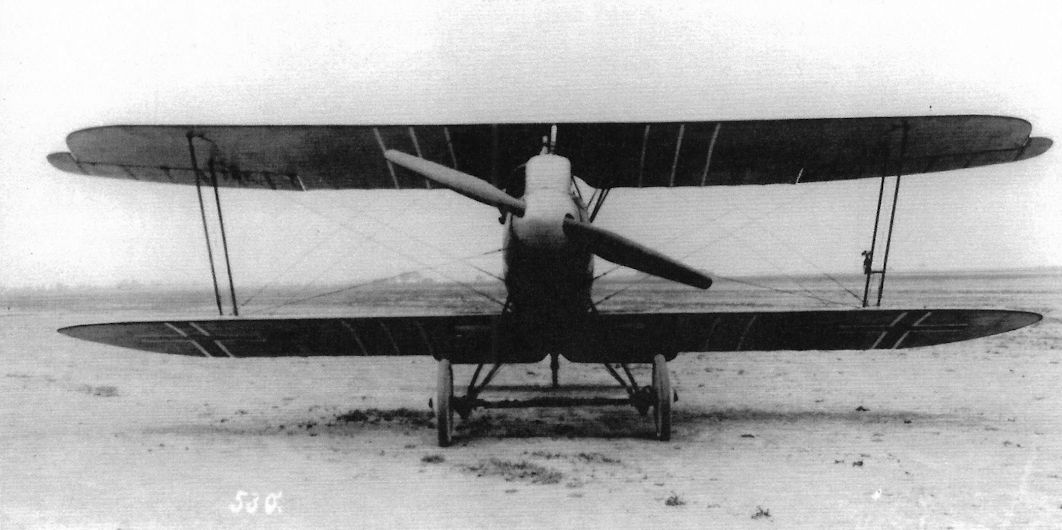
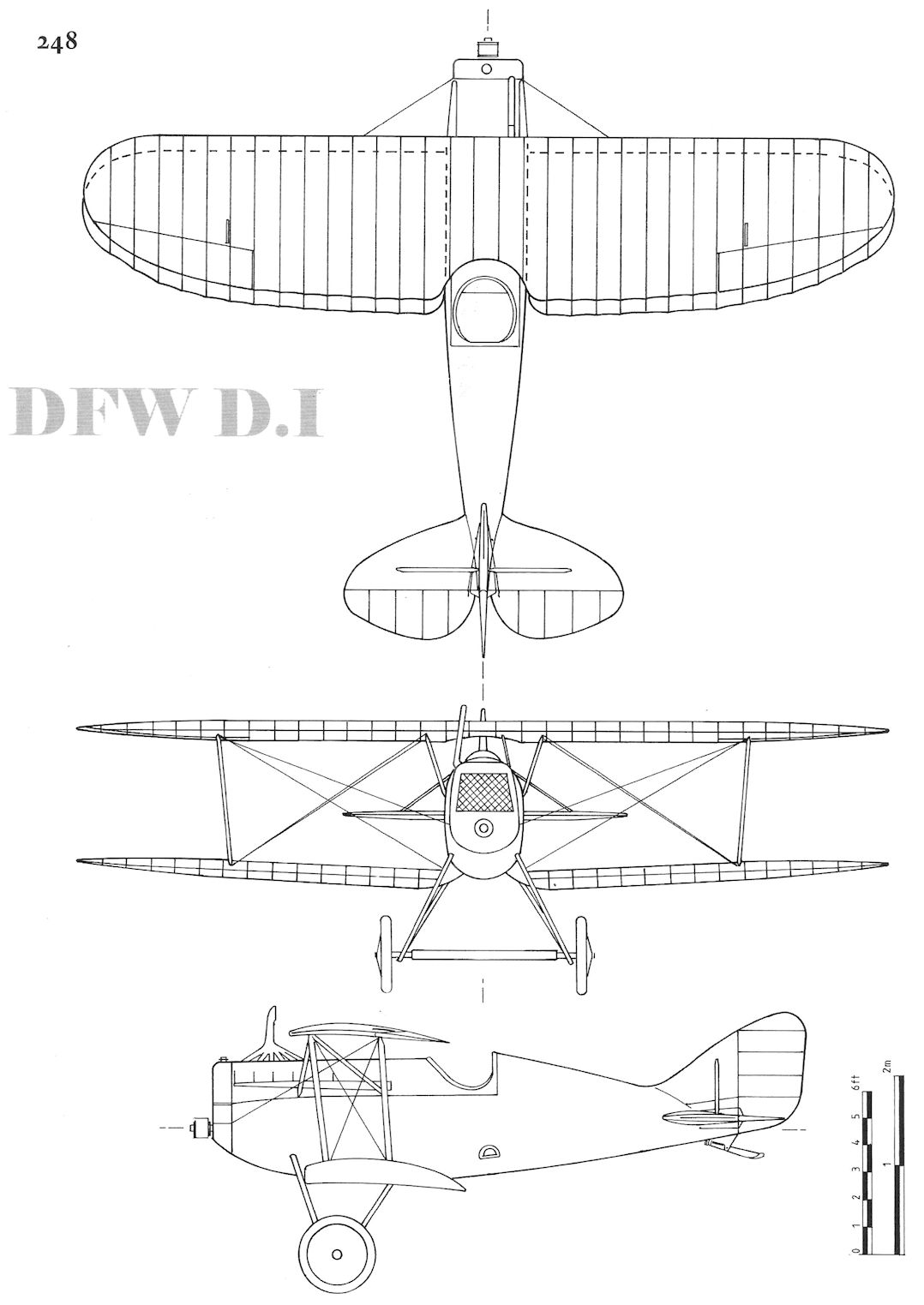
DFW D.I
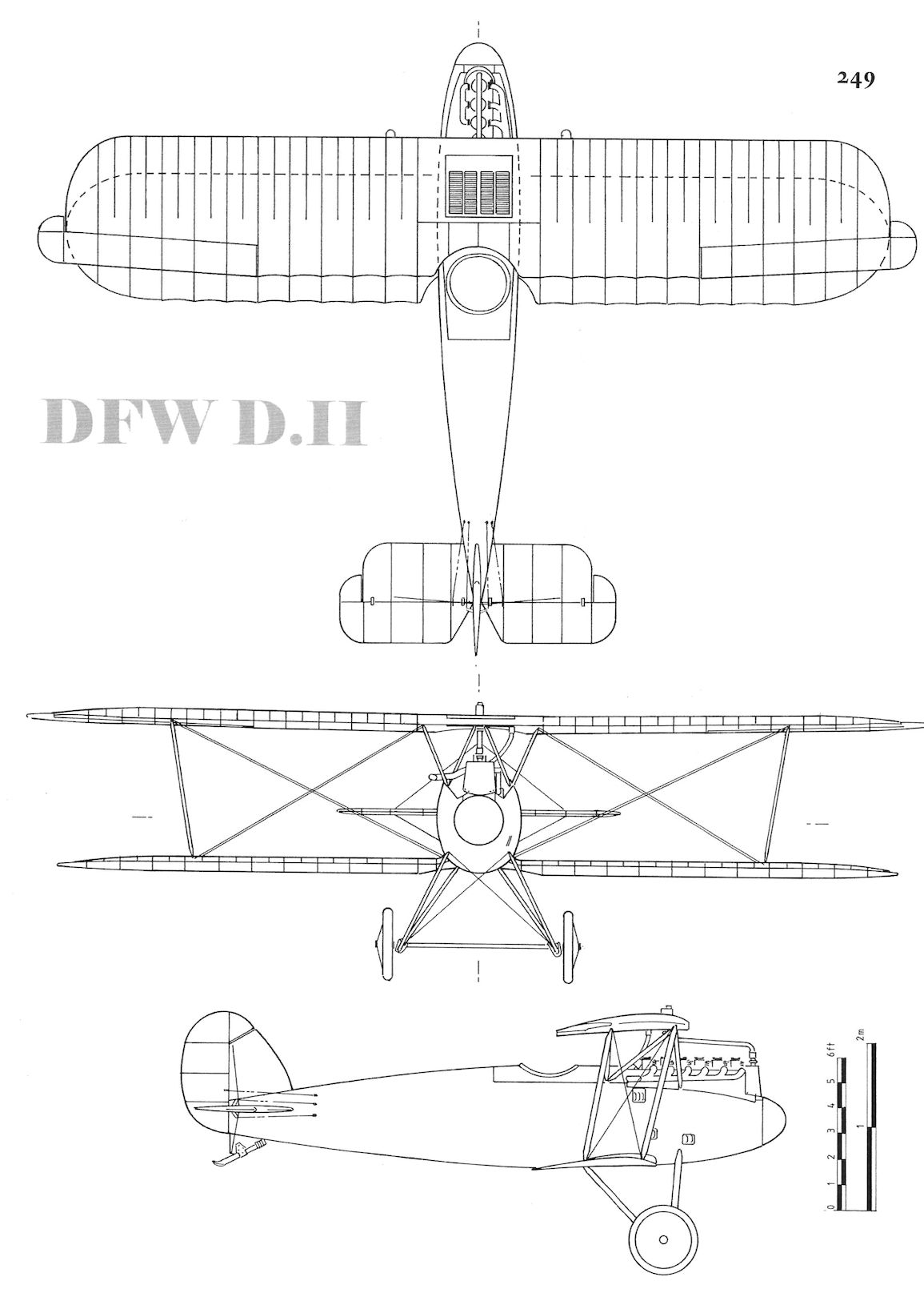
DFW D.II
DFW Dr.I
Designed in 1917 during the height of Germany's 'Triplane Craze', the DFW T 34-II, was a triplane fighter developed in parallel with the T 34-I biplane fighter prototype. The triplane prototype shared everything but the wing cellule with its biplane counterpart.
Like its biplane sibling, the T 34-II was powered by a 160 hp Mercedes D.III engine and was armed with two machine-guns. Both the biplane and triplane were submitted to the First Fighter Competition but were excluded from flight testing due to poor field of view for the pilot. In addition, the triplane was condemned for "unsuitable design", although details are not available.
However, a look at the photographs gives rise to the suspicion that the "unsuitable design" comment might be related to the T 34-II's excessive number of struts. Unlike the biplane prototype, the triplane had a two-bay wing cellule, which created extra weight and drag and seems unnecessary for such a small aircraft. At least, if the aircraft's structural design was efficient, there would have been no need for the two-bay cellule. Moreover, N-struts were used in profusion, which seems redundant.
Furthermore, to achieve sufficient gap between the wings to avoid aerodynamic interference with the airflow between the wings, the bottom set of wings was suspended below the fuselage on struts. And these struts made little use of the strength of the separate undercarriage struts.
The Sopwith triplane came out well before DFW's triplane fighter arrived on the scene, and the Fokker triplane also appeared earlier, so the DFW design team certainly had examples of successful triplane fighters for inspiration. Certainly neither featured the complex array of heavy, drag-producing struts featured by the DFW Dr.I. All in all the excessive number of struts makes a poor impression and justified the "unsuitable design" comment on its own. Was there even more wrong with the design than this?
No performance or dimensional data is available.
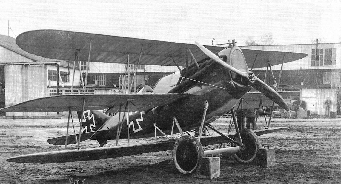
The DFW T 34-II triplane was developed in parallel with the T 34-I biplane fighter. Both were submitted to the First Fighter Competition but were excluded from flight trials due to a poor field of view for the pilot. The excessive number of struts are clearly shown in this view. (The Peter M. Bowers Collection/The Museum of Flight)
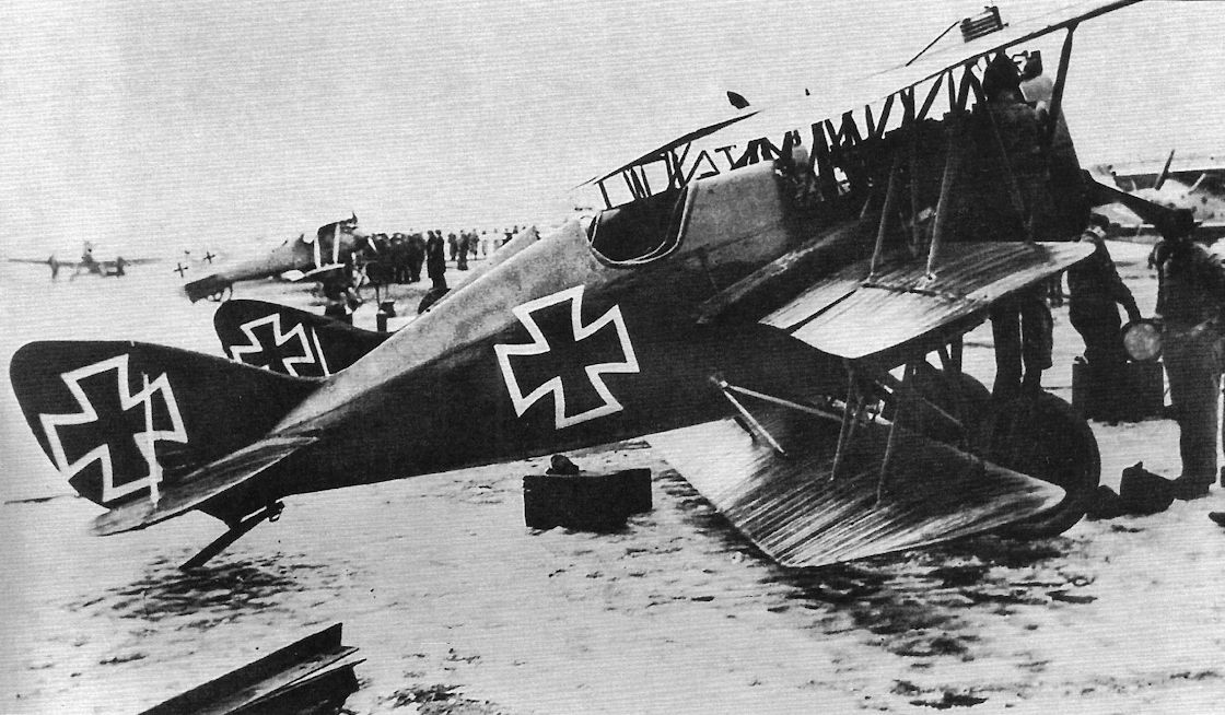
The DFW T 34-II was a compact triplane with many drag-creating bracing struts. The bottom wing was suspended below the fuselage to give more gap to prevent airflow interference between the wings. No performance data are available. (The Peter M. Bowers Collection/The Museum of Flight)
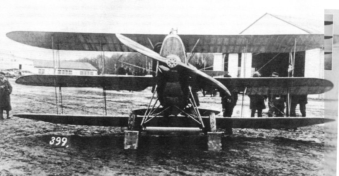
Three other triplane fighter essays of 1917 were the rotary-powered Euler Dr I, the 185hp Austro-Daimler powered Hansa-Brandenburg L 16 and the Korting engined DFW Dr I (main picture).
DFW C.VII & P.1
The next and last DFW two-seater design was the F 37, thought to have been designated the C.VII. The C.VII used the 220 hp Benz Bz.FVa installed in the C.VI to improve on the performance of the C.V The C.VII appears to have used the wing cellule tested in the C.VI although with the lower wingtips less rounded than those of the C.VI. The fuselage of the C.VII was more compact than the C.VI and a much larger rudder and fin were installed with different horizontal tail design, these changes being made to further improve maneuverability and handling qualities. In any case, the C.VII came too late to reach production or service.
Postwar a C.VII prototype was fitted with a 320 hp BMW.IV engine as an engine test-bed. The engine name plate had the old designation BMW.IIIa to obtain the flight permit from the Allied Monitoring Commission. Leutnant Franz Zeno Diemer reached a record altitude of 9,920 m on May 9th, 1919, and on June 17, 1919; however, the record was not recognized by the FAI at that time.
A postwar passenger conversion of the C.VII was also built. The resulting DFW P.1 had an enclosed cabin for two passengers in place of the observer's open cockpit. Photographs of aircraft D 187, the only P.1 built, are in this section. The Allied determination to destroy the German aviation industry as expressed in the terms of the Treaty of Versailles had the intended effect and DFW was soon put out of the aviation business.
DFW C-Type Specifications
DFW C.IV DFW C.V DFW C.VI DFW C.VII
Engine 150 hp Benz Bz.III 200 hp Benz Bz.IV 220 hp Benz Bz.IVa 220 hp Benz Bz.IVa
Span, Upper 13.30 m 13.27 m 13.60 m 13.60 m
Span, Lower - 12.80 m - -
Chord, Upper - 1.75 m - -
Chord, Lower - 1.75 m - -
Gap - 1.80 m - -
Wing Area 42.2 m2 41.52 m2 - 38.0 m2
Length 7.90 m 7.88 m 7.50 m 7.0 m
Height 3.3 m 3.26 m - 2.8 m
Empty Weight 720 kg 1,027 kg - 800 kg
Loaded Weight 1,230 kg 1,477 kg - 1,230 kg
Maximum Speed 135 km/h 155 km/h - 160 km/h
Climb to 1,000m - 4.0 minutes - 3.0 minutes
Climb to 2,000m - 7.0 minutes - -
Climb to 3,000m - 15.0 minutes - -
Climb to 4,000m - 25.0 minutes - -
Climb to 5,000m - 40.0 minutes -

The final DFW two-seater design to be completed had the internal company designation F 37; it is thought to have been assigned the military designation DFW C.VII but this is not confirmed. It was powered by a 220 hp Benz Bz.IVa. When fitted with a 260 hp BMW.IV engine postwar it achieved an altitude record of 7,700 m. (Peter M. Bowers Collection/Museum of Flight)


The final DFW two-seater design is thought to have been assigned the military designation DFW C.VII but this is not confirmed. It was powered by a 220 hp Benz Bz.lVa. (Peter M. Bowers Collection/Museum of Flight)

The DFW P.1 was a postwar passenger conversion of the DFW C.VII with cabin for two passengers. Like most aircraft of the time, the pilot's cockpit was open so the pilot could feel the wind and hear the wires more clearly, important clues to aircraft performance given the limited instrumentation. (Peter M. Bowers Collection/Museum of Flight)


The DFW P.1 postwar passenger conversion of the DFW C.VII with cabin for two passengers registered D 187, the only DFW P.1 built. Like the C.VII from which it was derived, the P.1 had balanced ailerons. (Peter M. Bowers Collection/Museum of Flight)

The DFW P.1 was also known as the DFW Limousine and the smiles on these passengers confirm the name was appropriate. The cabin decor was far more luxurious than the Spartan combat aircraft DFW previously built.

This DFW Limousine (P.1) drawing appeared in Flug-Welt in 1919 and provides useful details of the passenger cabin. Interestingly, the wide pilot's cockpit could also hold two crew-members on seats over the fuel tank.
DFW C.I C.1505/15 is in the left center background in front of the Fokker Eindecker in this photo of Feld-Flieger Abteilung 61. LVG B.I and Albatros B.II aircraft form part of this motley collection. (Bruno Schmaling)
DFW C.I C.1505/15 is in the left center background in front of the Fokker Eindecker in this photo of Feld-Flieger Abteilung 61. LVG B.I and Albatros B.II aircraft form part of this motley collection. (Bruno Schmaling)

Lt. Rudolf Stark, shown here with Pfalz fighters he flew in Jasta 34b, ended the war as Staffelfuhrer of Jasta 35b with 11 victories. Postwar he wrote the well-known book Wings of War, published in 1933, based on his wartime experiences. The Fokker D.VII in the USAF Museum carries the markings of the D.VII Stark flew when in command of Jasta 35b. The fuselage stripe was in lilac, as was the spinner.
The DFW R.I 11/15 in its final form. The machine in the foreground is a SSW D.1 fighter.
The DFW R.I is its final configuration is joined by an SSW D.I fighter to provide a size comparison. The R.I has full camouflage paint and all the other upgrades. The massive DFW R.I was a 'canvas overcast'. (Peter M. Grosz Collection/SDTB)
The DFW R.I in its final configuration with fixed rudder and larger rudders. An SSW D.I is parked in front of the R.I to provide a size comparison.
DFW C.V at Cheb airfield at the Czech Air Force School about 1921. A Breguet 14 is in the left background.
To the left of this Finnish Nieuport 23 is the nose of a DFW C.V in Finnish national markings after the war.